
FHX-700BT - Car stereo PIONEER - Free user manual and instructions
Find the device manual for free FHX-700BT PIONEER in PDF.

User questions about FHX-700BT PIONEER
0 question about this device. Answer the ones you know or ask your own.
Ask a new question about this device
Download the instructions for your Car stereo in PDF format for free! Find your manual FHX-700BT - PIONEER and take your electronic device back in hand. On this page are published all the documents necessary for the use of your device. FHX-700BT by PIONEER.
USER MANUAL FHX-700BT PIONEER
REPRODUCTOR DE CD CON RECEPTOR RDS
CD RDS-EMPFÄNGER
CD RDS-ONTVANGER
CD RDS ПРИЕМНИК
FH-X700BT
Pioneer
Installation Manual
- Check all connections and systems before final installation.
- Do not use unauthorized parts as this may cause malfunctions.
- Consult your dealer if installation requires drilling of holes or other modifications to the vehicle.
- Do not install this unit where: — it may interfere with operation of the vehicle. — it may cause injury to a passenger as a result of a sudden stop.
- The semiconductor laser will be damaged if it overheats. Install this unit away from hot places such as near the heater outlet.
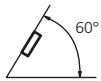
- Optimum performance is obtained when the unit is installed at an angle of less than 60°.
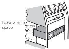
- When installing, to ensure proper heat dispersal when using this unit, make sure you leave ample space behind the rear panel and wrap any loose cables so they are not blocking the vents.
text_image
Leave ample space 5 cm 5 cm- Use commercially available parts when installing.
How to install
This unit can be installed properly using either of the methods in the below list.
• Installation with the holder
- Installation using the screw holes on the side of the unit
Before installing this unit
1 Remove the trim ring.
text_image
Technical diagram showing a pipe fitting with an inset view of the pipe's opening and assembly steps.① Trim ring
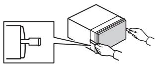
2 Insert the supplied extraction keys into both sides of the unit until they click into place.
natural_image
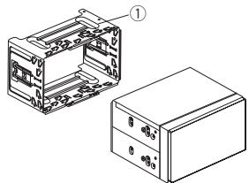
Diagram showing a mechanical assembly with hands connecting a box to a component (no text or symbols present)3 Pull the unit out of the holder.
Remove the holder.
Installation
natural_image
Technical line drawing of two electronic components with labeled parts (no text or symbols present)① Holder (factory-supplied part)
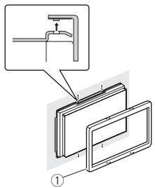
2 Install this unit.
text_image
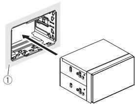
Diagram showing a file transfer or storage operation with labeled components and directional arrows① Dashboard
Installation with the holder
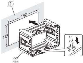
1 Install the holder into the dashboard.
After inserting the holder into the dashboard, select and bend the tabs appropriate to the thickness of the dashboard material. (Install this unit as firmly as possible using the top and bottom tabs. To secure this unit, bend the tabs 90 degrees.)
text_image
① 182 112 ②① Dashboard ② Holder (factory-supplied part)
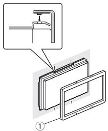
3 Attach the trim ring.

text_image
Technical diagram showing a pipe installation with labeled components and a magnified detail view① Trim ring
Removing the holder
The procedure is the same as that for Before installing this unit. For details, refer to Before installing this unit on this page.
Installation
Installation using the screw holes on the side of the unit
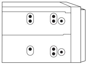
● Fastening the unit to the factory radio-mounting bracket.
Position the unit so that its screw holes are aligned with the screw holes of the bracket, and tighten the screws at 3 locations on each side.
natural_image
Simple line drawing of a two-tiered electronic device with four circular components (no text or symbols)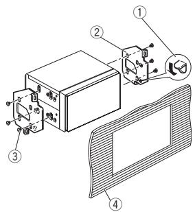
text_image
Technical diagram of a device with numbered components and labeled parts, likely illustrating a mechanical or electronic assembly.① If the pawl gets in the way, bend it down.
② Factory radio mounting bracket
③ Truss (5 mm × 8 mm) screws
④ Dashboard or console
Connections
Important
- When installing this unit in a vehicle without an ACC (accessory) position on the ignition switch, failure to connect the red cable to the terminal that detects operation of the ignition key may result in battery drain.

ACC position

No ACC position
- Use of this unit in conditions other than the following could result in fire or malfunction.
— Vehicles with a 12-volt battery and negative grounding.
— Speakers with 50 W (output value) and 4 Ω to 8 Ω (impedance value). - To prevent a short-circuit, overheating or malfunction, be sure to follow the directions below.
— Disconnect the negative terminal of the battery before installation.
— Secure the wiring with cable clamps or adhesive tape. Wrap adhesive tape around wiring that comes into contact with metal parts to protect the wiring.
— Place all cables away from moving parts, such as the shift lever and seat rails.
— Place all cables away from hot places, such as near the heater outlet.
— Do not connect the yellow cable to the battery by passing it through the hole to the engine compartment.
— Cover any disconnected cable connectors with insulating tape.
— Do not shorten any cables.
— Never cut the insulation of the power cable of this unit in order to share the power with other devices. The current capacity of the cable is limited.
— Use a fuse of the rating prescribed.
— Never wire the negative speaker cable directly to ground.
— Never band together negative cables of multiple speakers.
- When this unit is on, control signals are sent through the blue/white cable. Connect this cable to the system remote control of an external power amp or the vehicle's auto-antenna relay control terminal (max. 300 mA 12 V DC). If the vehicle is equipped with a glass antenna, connect it to the antenna booster power supply terminal.
- Never connect the blue/white cable to the power terminal of an external power amp. Also, never connect it to the power terminal of the auto antenna. Doing so may result in battery drain or a malfunction.
- The black cable is ground. Ground cables for this unit and other equipment (especially, high-current products such as power amps) must be wired separately. If they are not, an accidental detachment may result in a fire or malfunction.
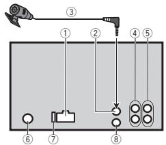
This unit
text_image
Diagram of a device with numbered components and labeled parts, likely for electrical or mechanical assembly reference.① Power cord input
② Microphone input
③ Microphone
4 m
④ Rear output or subwoofer output
⑤ Front output
Connections
⑥ Antenna input
⑦ Fuse (10 A)
⑧ Wired remote input
Hard-wired remote control adapter can be connected (sold separately).
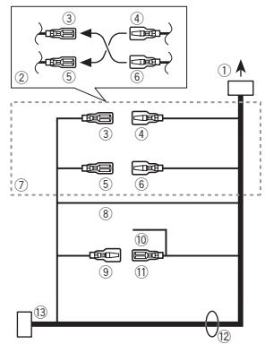
Power cord
flowchart
graph TD
    A["①"] --> B["②"]
    B --> C["③"]
    C --> D["④"]
    D --> E["⑤"]
    E --> F["⑥"]
    F --> G["⑦"]
    G --> H["⑧"]
    H --> I["⑨"]
    I --> J["⑩"]
    J --> K["⑪"]
    K --> L["⑫"]
    L --> M["⑬"]
    M --> N["⑭"]
    N --> O["⑮"]
    O --> P["⑯"]
    P --> Q["⑰"]
    Q --> R["⑱"]
    R --> S["⑲"]
    S --> T["⑳"]
    T --> U["⑴"]
    U --> V["⑤"]
    V --> W["⑥"]
    W --> X["⑦"]
    X --> Y["⑧"]
    Y --> Z["⑨"]
    Z --> AA["⑩"]
    AA --> AB["⑪"]
    AB --> AC["⑫"]
① To power cord input
② Depending on the kind of vehicle, the function of ③ and ⑤ may be different. In this case, be sure to connect ④ to ⑤ and ⑥ to ③.
③ Yellow
Back-up (or accessory)
④ Yellow
Connect to the constant 12 V supply terminal.
⑤ Red
Accessory (or back-up)
⑥ Red
Connect to terminal controlled by ignition switch (12 V DC).
⑦ Connect leads of the same color to each other.
⑧ Black (chassis ground)
⑨ Blue/white
The pin position of the ISO connector will differ depending on the type of vehicle. Connect ⑨ and ⑪ when Pin 5 is an antenna control type. In another type of vehicle, never connect ⑨ and ⑪.
⑩ Blue/white
Connect to system control terminal of the power amp (max. 300 mA 12 V DC).
⑪ Blue/white
Connect to auto-antenna relay control terminal (max. 300 mA 12 V DC).
⑫ Speaker leads
White: Front left ⊕
White/black: Front left ⊖
Gray: Front right ⊕
Gray/black: Front right ⊖
Green: Rear left ⊕ or subwoofer ⊕
Green/black: Rear left ⊖ or subwoofer ⊖
Violet: Rear right ⊕ or subwoofer ⊕
Violet/black: Rear right ⊖ or subwoofer ⊖
⑬ ISO connector
In some vehicles, the ISO connector may be divided into two. In this case, be sure to connect to both connectors.
Notes
- Change the initial setting of this unit (refer to the operation manual). The subwoofer output of this unit is monaural.
- When using a subwoofer of 70 W (2Ω), be sure to connect the subwoofer to the violet and violet/black leads of this unit. Do not connect anything to the green and green/black leads.
Connections
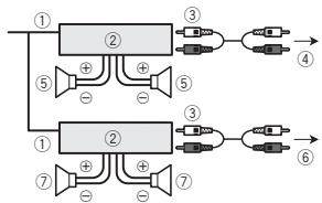
Power amp (sold separately)
Perform these connections when using the optional amplifier.
flowchart
graph TD
    A["①"] --> B["②"]
    B --> C["③"]
    C --> D["④"]
    B --> E["⑤"]
    E --> F["⑥"]
    G["⑦"] --> H["⑧"]
    H --> I["⑨"]
    J["①"] --> K["②"]
    K --> L["③"]
    L --> M["④"]
    K --> N["⑤"]
    N --> O["⑥"]
    P["⑦"] --> Q["⑧"]
    Q --> R["⑨"]
    S["③"] --> T["④"]
    T --> U["⑥"]
① System remote control
Connect to Blue/white cable.
② Power amp (sold separately)
③ Connect with RCA cables (sold separately)
④ To Front output
⑤ Front speaker
⑥ To Rear output or subwoofer output
⑦ Rear speaker or subwoofer
Installing the microphone

CAUTION
It is extremely dangerous to allow the micro-phone lead to become wound around the steering column or shift lever. Be sure to install the unit in such a way that it will not obstruct driving.
Note
Install the microphone in a position and orientation that will enable it to pick up the voice of the person operating the system.
When installing the microphone on the sun visor
1 Install the microphone on the microphone clip.
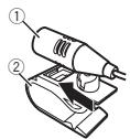
① Microphone
② Microphone clip
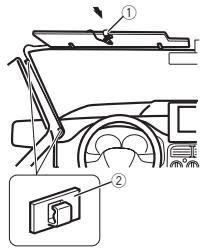
2 Install the microphone clip on the sun visor.
With the sun visor up, install the microphone clip. (Lowering the sun visor reduces the voice recognition rate.)
text_image
Diagram showing car frontview and rearview components with labeled parts ① and ②, including a close-up inset of the rear window.① Microphone clip
② Clamp
Use separately sold clamps to secure the lead where necessary inside the vehicle.
When installing the microphone on the steering column
1 Install the microphone on the microphone clip.
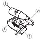
① Microphone
② Microphone base
③ Microphone clip
④ Fit the microphone lead into the groove.
- Microphone can be installed without using microphone clip. In this case, detach the microphone base from the microphone clip. To detach the microphone base from the microphone clip, slide the microphone base.
Installing the microphone
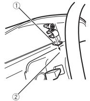
2 Install the microphone clip on the steering column.
text_image
Diagram showing car seatbelting technique with labeled parts ① and ②
text_image
Diagram showing car interior with steering wheel and device labeled in Chinese① Double-sided tape
② Install the microphone clip on the rear side of the steering column.
③ Clamp
Use separately sold clamps to secure the lead where necessary inside the vehicle.
Adjusting the microphone angle

The microphone angle can be adjusted.

Important
text_image
Technical diagram showing a mechanical assembly with labeled components and an inset detail view.natural_image
Diagram showing a mechanical device connected to a box, with hands adjusting the components (no text or symbols present)natural_image
Technical line drawing of two electronic components with labeled parts (no text or symbols present)text_image
Diagram showing a file transfer or storage operation with labeled components and directional arrows① Tableau de bord
text_image
Technical diagram showing a pipe installation with labeled components and a magnified detail view.natural_image
Simple line drawing of a two-tier electronic device with four circular components on top (no text or symbols)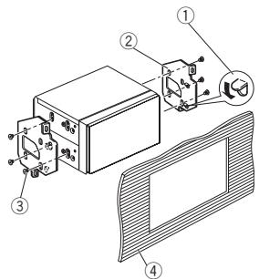
text_image
Technical diagram of a device with numbered components and labeled parts, likely illustrating a mechanical or electronic assembly.text_image
Diagram of a device layout with numbered components including a connector, socket, and indicator lightstext_image
Diagram showing car frontview and rearview components with labeled parts ① and ②, including a close-up inset of the rear window.text_image
Diagram showing car seatbelting technique with labeled parts ① and ②
text_image
Diagram showing car interior with steering wheel and device labeled in Chinesetext_image
Technical diagram showing a mechanical assembly with labeled components and an inset detail view.① Guarnizione
natural_image
Diagram showing a hand inserting a block into a device (no text or symbols present)Installazione
natural_image
Technical line drawing of two electronic components: a rectangular housing with internal wiring and a separate box with ports (no text or symbols)text_image
Diagram showing file transfer from a storage cabinet to a file holder, with labeled components and directional arrow.① Cruscotto
text_image
Technical diagram showing a pipe installation with labeled components and a magnified detail view① Guarnizione
natural_image
Simple line drawing of a two-tiered electronic device with four circular components (no text or symbols)
text_image
Technical diagram of a device with numbered components and labeled parts, likely illustrating a mechanical or electronic assembly.text_image
Diagram of a device layout with numbered components including a sensor, connector, and labeled parts 1 through 8.text_image
Diagram showing car frontview and rearview components with labeled parts ① and ②, including a close-up inset of the rear window.text_image
Diagram showing car seatbelting instructions with labeled parts ① and ②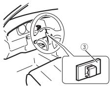
text_image
Diagram showing car interior with steering wheel and device labeled in Chinesetext_image
Technical diagram showing a mechanical assembly with labeled components and an inset detail view.① Anillo de guarnición
natural_image
Diagram showing a mechanical device connected to a box, with hands holding it (no text or symbols present)natural_image
Technical line drawing of two electronic components with labeled parts (no text or symbols present)text_image
Diagram showing a file transfer or storage operation with labeled components and directional arrows① Salpicadero
text_image
Technical diagram showing a pipe installation with labeled components and a magnified detail view① Anillo de guarnición
natural_image
Simple line drawing of a two-tiered electronic device with four circular components (no text or symbols)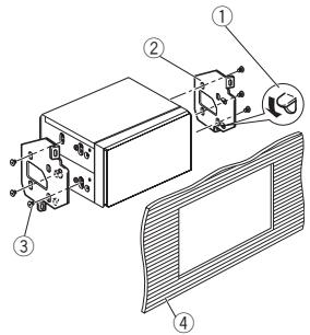
text_image
Technical diagram of a device with numbered components and labeled parts, likely for assembly or maintenance instructions.text_image
Diagram of a device layout with numbered components and labeled parts, likely for electrical or mechanical assembly.text_image
Diagram showing car frontview and rearview components with labeled parts ① and ②, including a close-up inset of the rear window.① Pinza
② Abrazadera
text_image
Diagram showing car seatbelting instructions with labeled parts ① and ②
text_image
Diagram showing car interior with steering wheel and device labeled in Chinesetext_image
Technical diagram showing a pipe installation with labeled components and a magnified detail view① Einpassungsring
natural_image
Diagram showing hands operating a mechanical device with a box, no text or symbols presentnatural_image
Technical line drawing of a mechanical housing and its internal components (no text or symbols)text_image
Diagram showing a file transfer or storage operation with labeled components and directional arrows① Armaturenbrett
text_image
Technical diagram showing a pipe connection with labeled components and a magnified detail view① Einpassungsring
natural_image
Simple line drawing of a two-tiered electronic device with four circular components on top (no text or symbols)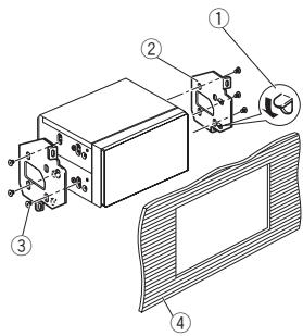
text_image
Technical diagram of a device assembly with numbered components and labeled partstext_image
Diagram of a device with numbered components and labeled parts, including a sensor and control unit.text_image
Diagram showing car frontview and rearview components with labeled parts ① and ②, including a close-up inset of the rear window.① Mikrofonclip
② Klammer
text_image
Diagram showing car seatbelting instructions with labeled parts ① and ②
text_image
Diagram showing car interior with steering wheel and attached device labeled ③text_image
Technical diagram showing a pipe fitting with an inset view of the pipe's opening and assembly steps.① Sierlijst
natural_image
Diagram showing a mechanical assembly with hands connecting a box to a component (no text or symbols present)natural_image
Technical line drawing of two electronic components with labeled parts (no text or symbols present)text_image
Diagram showing a file transfer or storage operation with labeled components and directional arrows① Dashboard
text_image
Technical diagram showing a pipe installation with labeled components and a magnified detail view.① Sierlijst
natural_image
Simple line drawing of a two-tiered electronic device with four circular components (no text or symbols)
text_image
Technical diagram of a device with numbered components and labeled parts, likely illustrating a mechanical or electronic assembly.text_image
Diagram of a device with numbered components and labeled parts, including a probe, connector, and air vent.① Ingang stroomkabel
② Microfooningang
Verbindingen
text_image
Diagram showing car front panel and rearview mirror assembly with labeled parts① Microfoonklem
② Klem
text_image
Diagram showing car seatbelt mechanism with labeled parts ① and ②
text_image
Diagram showing car interior with steering wheel and attached electrical switch, labeled with number ③text_image
Technical diagram showing a pipe installation with labeled components and a magnified detail viewnatural_image
Diagram showing a mechanical assembly with hands connecting a block to a housing (no text or symbols present)natural_image
Technical illustration of two electronic components with labeled parts (no text or symbols present)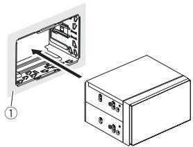
text_image
Diagram showing a file transfer or storage operation with labeled components and directional arrowУстановка
① Приборная панель
3 Установите рамку.
text_image
Technical diagram showing a pipe connection with labeled components and a magnified detail viewnatural_image
Simple line drawing of a two-tiered electronic device with four circular components on top (no text or symbols)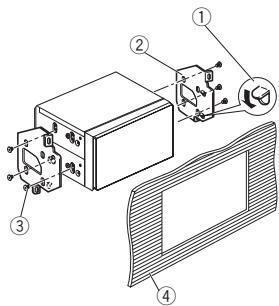
text_image
Technical diagram of a device with numbered components and labeled parts, likely for assembly or maintenance instructions.text_image
Diagram of a device layout with numbered components including a sensor, connector, and labeled parts 1 through 8.text_image
Diagram showing car front panel and rearview mirror assembly with labeled partstext_image
Diagram showing car seatbelt mechanism with labeled parts ① and ②
text_image
Diagram showing car interior with steering wheel and attached electrical switch, labeled with number ③PIONEER ELECTRONICS (USA) INC.
P.O. Box 1540, Long Beach, California 90801-1540, U.S.A.
TEL: (800) 421-1404
PIONEER ELECTRONICS OF CANADA, INC.
340 Ferrier Street, Unit 2, Markham, Ontario L3R 2Z5, Canada
TEL: 1-877-283-5901
TEL: 905-479-4411
PIONEER ELECTRONICS ASIACENTRE PTE. LTD.
253 Alexandra Road, #04-01, Singapore 159936
TEL: 65-6472-7555
PIONEER ELECTRONICS AUSTRALIA PTY. LTD.
5 Arco Lane, Heatherton, Victoria, 3202 Australia
TEL: (03) 9586-6300
PIONEER ELECTRONICS DE MEXICO, S.A. de C.V.
Blvd.Manuel Avila Camacho 138 10 piso
Col.Lomas de Chapultepec, Mexico, D.F. 11000
TEL: 55-9178-4270
先鋒股份有限公司
台北市內湖區瑞光路407號8樓
電話:886-(0)2-2657-3588
先鋒電子(香港)有限公司
香港九龍長沙灣道909號5樓
電話:852-2848-6488