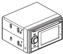
USER MANUAL AVIC-F320BT PIONEER
INSTALLATION MANUAL MANUEL D'INSTALLATION
ABOUT YOUR NEW NAVIGATION SYSTEM AND THIS MANUAL 3
02 IMPORTANT SAFEGUARDS
PLEASE READ ALL OF THESE
INSTRUCTIONS REGARDING YOUR
NAVIGATION SYSTEM AND RETAIN THEM
FOR FUTURE REFERENCE 4
03 Connecting the System
Precautions before connecting the system 5
Before installing this product 5
To prevent damage 6
– Notice for the blue/white lead 6
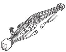
Parts supplied 7
Connecting the system 8
Connecting the power cord (1) 10
Connecting the power cord (2) 12
When connecting to separately sold power amp 13
04 Installation
Precautions before installation 14
To guard against electromagnetic interference 14
Before installing 14
Installing this navigation system 15
- Installation notes 15
- Parts supplied 16
- Before installing this navigation unit 17
- Installation with the holder and side bracket 17
- Installation using the screw holes on the side of the navigation unit 18
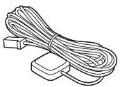
Installing the GPS aerial 19
- Installation notes 19
- Parts supplied 19
- When installing the aerial inside the vehicle (on the dashboard or rear shelf) 20
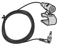
Installing the microphone 21
- Parts supplied 21
- Mounting on the sun visor 21
- Installation on the steering column 22
- Adjusting the microphone angle 22
05 After Installation
After Installing this navigation system 23
ABOUT YOUR NEW NAVIGATION SYSTEM AND THIS MANUAL
- The navigation features of this product are intended solely to aid you in the operation of your vehicle. It is not a substitute for your attentiveness, judgement and care when driving.
- Never use this navigation system to route to hospitals, police stations, or similar facilities in an emergency. Please call the appropriate emergency number.
- Do not operate this navigation system if doing so in any way will divert your attention from the safe operation of your vehicle. Traffic restrictions and advisories currently in force should always take precedence over guidance given by this product. Always obey current traffic restrictions, even if this product provides contrary advice.
- This manual explains how to install this navigation system in your vehicle. Operation of this navigation system is explained in the separate manuals for the navigation system.
- Do not install this product where it may (i) obstruct the driver's vision, (ii) impair the performance of any of the vehicle's operating systems of safety features, including airbags, hazard lamp buttons or (iii) impair the driver's ability to safely operate the vehicle. In some cases, it may not be possible to install this product because of the vehicle type or the shape of the vehicle interior.
WARNING
Pioneer does not recommend that you install your navigation system yourself. We recommend that only authorised Pioneer service personnel, who have special training and experience in mobile electronics, set up and install this product. NEVER SERVICE THIS PRODUCT YOURSELF. Installing or servicing this product and its connecting cables may expose you to the risk of electric shock or other hazards, and can cause damage to the navigation system that is not covered by warranty.
PLEASE READ ALL OF THESE INSTRUCTIONS REGARDING YOUR NAVIGATION SYSTEM AND RETAIN THEM FOR FUTURE REFERENCE
1 Read this manual fully and carefully before installing your navigation system.
2 Keep this manual handy for future reference.
3 Pay close attention to all warnings in this manual and follow the instructions carefully.
4 The first time the system is started up, the message “Preparing to start up system... please wait” may be displayed since battery power remaining may be quite low. If you see this message, do not operate the unit until after the message “Ready to start up system.” is displayed.
5 This navigation system may in certain circumstances display erroneous information regarding the position of your vehicle, the distance of objects shown on the screen, and compass directions. In addition, the system has certain limitations, including the inability to identify one-way streets, temporary traffic restrictions and potentially unsafe driving areas. Please exercise your own judgement in the light of actual driving conditions.
6 As with any accessory in your vehicle's interior, the navigation system should not divert
your attention from the safe operation of your vehicle. If you experience difficulty in operating the system or reading the display, please make adjustments while safely parked.
7 Please remember to wear your seat belt at all times while operating your vehicle. If you are ever in an accident, your injuries can be considerably more severe if your seat belt is not properly fastened.
8 Certain country and government laws may prohibit or restrict the placement and use of this system in your vehicle. Please comply with all applicable laws and regulations regarding the use, installation and operation of your navigation system.
Precautions before connecting the system

CAUTION
- If you decide to perform the installation yourself, and have special training and experience in the mobile electronics installations, please carefully follow all of the steps in the installation manual.
- Secure all wiring with cable clamps or electrical tape. Do not allow any bare wiring to remain exposed.
- Do not directly connect the yellow lead of this product to the vehicle battery. If the lead is directly connected to the battery, engine vibration may eventually cause the insulation to fail at the point where the wire passes from the passenger compartment into the engine compartment. If the yellow lead's insulation tears as a result of contact with metal parts, short-circuiting can occur, resulting in considerable danger.
- It is extremely dangerous to allow the cables to become wound around the steering column or gearstick. Be sure to install this product, its cables, and wiring away in such a way that they will not obstruct or hinder driving.
- Make sure that the cables and wires are routed and secured so they will not interfere with or become caught in any of the vehicle's moving parts, especially the steering wheel, gearstick, handbrake, sliding seat tracks, doors, or any of the vehicle's controls.
- Do not route wires where they will be exposed to high temperatures. If the insulation heats up, wires may become damaged, resulting in a short circuit or malfunction and permanent damage to the product.
-
Do not cut the GPS aerial cable to shorten it or use an extension to make it longer. Altering the aerial cable could result in a short circuit or malfunction.
-
Do not shorten any leads. If you do, the protection circuit (fuse holder, fuse resistor or filter, etc.) may fail to work properly.
- Never feed power to other electronic products by cutting the insulation of the power supply lead of the navigation system and tapping into the lead. The current capacity of the lead will be exceeded, causing overheating.
Before installing this product
- Use this unit with a 12-volt battery and negative earthing only. Failure to do so may result in a fire or malfunction.
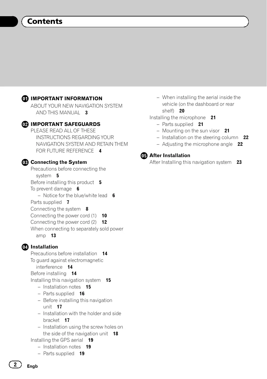
- To avoid shorts in the electrical system, be sure to disconnect the (−) battery cable before beginning installation.
natural_image
Illustration of a hand holding a battery with a switch and power plug (no text or symbols)

To prevent damage

WARNING
- Use speakers over 50 W (output value) and between 4Ω to 8Ω (impedance value). Do not use 1Ω to 3Ω speakers for this unit.
- The black lead is earth. Please earth this lead separately from the earth of high-current products such as power amps. Do not earth more than one product together with the earth from another product. For example, you must separately earth any amp unit away from the earth of this navigation system. Connecting earths together can cause a fire and/or damage the products if their earths became detached.
-
When replacing the fuse, be sure to only use a fuse of the rating prescribed on this product.
-
When disconnecting a connector, pull the connector itself. Do not pull the lead, as you may pull it out of the connector.
- This product cannot be installed in a vehicle without ACC (accessory) position on the ignition switch.

text_image
OFF ACC ON START
ACC position

text_image
OFF
ON
START
No ACC position
- To avoid short-circuiting, cover the disconnected lead with insulating tape. It is especially important to insulate all unused speaker leads, which if left uncovered may cause a short circuit.
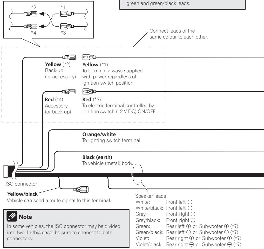
- Attach the connectors of the same colour to the corresponding coloured port, i.e., blue connector to the blue port, black to black, etc.
- Refer to the owner's manual for details on connecting the power amp and other units, then make connections accordingly.
- Since a unique BPTL circuit is employed, do not directly earth the side of the speaker lead or connect the sides of the speaker leads together. Be sure to connect the side of the speaker lead to the side of the speaker lead on this navigation system.
Notice for the blue/white lead
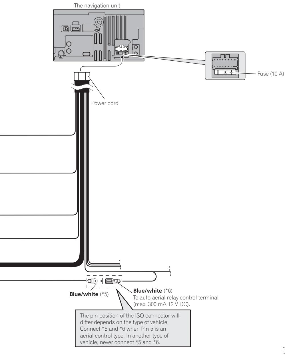
- When this unit is turned on, a control signal is output through the blue/white cable. Connect it to an external power amp's system remote control or the vehicle's auto-aerial relay control terminal (max. 300 mA, 12 V DC). If the vehicle is equipped with a glass aerial, connect the cable to the aerial booster power supply terminal.
- Never connect the blue/white cable to an external power amp's power terminal. Also, never connect it to the power terminal of the auto aerial. Otherwise, battery drain or malfunction may result.
- Be sure not to use this lead as the power supply lead for the auto-aerial or aerial booster. Such connection could cause excessive current drain and malfunction.
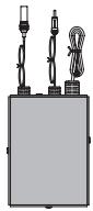
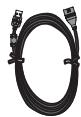
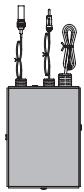
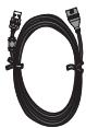
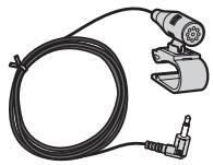
Connecting the System
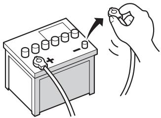
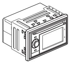
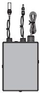
Parts supplied
natural_image
Line drawing of a rectangular electronic device with ports and a control panel (no text or symbols)
The navigation unit

natural_image
Pure electrical circuit lines without any symbols
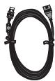
Power cord
RDS-TMC tuner
USB connector
natural_image
Line drawing of a coiled cable with two connectors (no text or symbols)
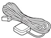
GPS aerial
natural_image
Illustration of a black-and-white photo of a coiled cable with a mechanical tool and clamp (no text or symbols)
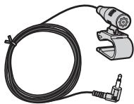
Microphone

Connecting the system
text_image
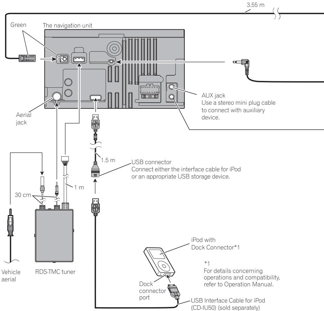
Green
The navigation unit
3.55 m
Aerial jack
30 cm
1 m
Vehicle aerial
RDS-TMC tuner
AUX jack
Use a stereo mini plug cable to connect with auxiliary device.
1.5 m
USB connector
Connect either the interface cable for iPod or an appropriate USB storage device.
iPod with Dock Connector*1
*1
For details concerning operations and compatibility, refer to Operation Manual.
Dock connector port
USB Interface Cable for iPod (CD-IU50) (sold separately)
Connecting the System
text_image
GPS aerial
4 m
Microphone
WIRED REMOTE INPUT
Please see the Instruction
Manual for the Wired Remote
Control Adapters (sold separately).

WARNING
To avoid the risk of accident and the potential violation of applicable laws, this product should never be used while the vehicle is being driven except for navigation purposes.

Connecting the power cord (1)

Note
Depending on the kind of vehicle, the function of *2 and *4 may be different. In this case, be sure to connect *1 to *4 and *3 to *2.

Notes
- When a subwoofer (*7) is connected to this navigation system instead of a rear speaker, change the rear output setting in the Initial Setting. (Refer to Operation Manual.) The subwoofer output of this navigation system is monaural.
- When using a subwoofer of 70 W (2 Ω), be sure to connect with violet and violet/black leads of this navigation system. Do not connect anything with green and green/black leads.
flowchart
graph TD
    A["ISO connector"] --> B["Yellow (*2) Back-up (or accessory)"]
    A --> C["Red (*4) Accessory (or back-up)"]
    A --> D["Orange/white To lighting switch terminal."]
    A --> E["Black (earth) To vehicle (metal) body."]
    A --> F["Yellow/black Vehicle can send a mute signal to this terminal."]
    G["Green and green/black leads."] --> H["Connect leads of the same colour to each other."]
    I["Note"] --> J["In some vehicles, the ISO connector may be divided into two. In this case, be sure to connect to both connectors."]
    K["Speaker leads"] --> L["White: Front left ⊕"]
    K --> M["White/black: Front left ⊖"]
    K --> N["Grey: Front right ⊕"]
    K --> O["Grey/black: Front right ⊖"]
    K --> P["Green: Rear left ⊕ or Subwoofer ⊕ (*7)"]
    K --> Q["Green/black: Rear left ⊖ or Subwoofer ⊖ (*7)"]
    K --> R["Violet: Rear right ⊕ or Subwoofer ⊕ (*7)"]
    K --> S["Violet/black: Rear right ⊖ or Subwoofer ⊖ (*7)"]
Connecting the System
text_image
The navigation unit
Power cord
Fuse (10 A)
Blue/white (*5)
Blue/white (*6)
To auto-aerial relay control terminal
(max. 300 mA 12 V DC).
The pin position of the ISO connector will
differ depends on the type of vehicle.
Connect *5 and *6 when Pin 5 is an
aerial control type. In another type of
vehicle, never connect *5 and *6.
Connecting the power cord (2)
flowchart
graph TD
    A["The navigation unit"] --> B["Power cord"]
    B --> C["Light green"]
    C --> D["Warning: Light green leads at power connector designed to detect parked status and must be connected to the power supply side of the handbrake switch. Improper connection or use of this lead may violate applicable law and may result in serious injury or damage."]
    D --> E["Power supply side"]
    E --> F["Earth side"]
    F --> G["Handbrake switch"]
Connecting the System
When connecting to separately sold power amp
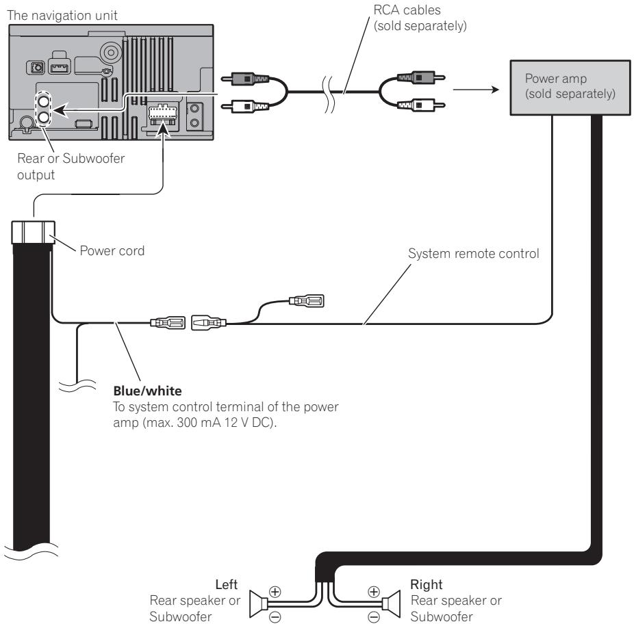
flowchart
graph TD
    A["The navigation unit"] --> B["Rear or Subwoofer output"]
    B --> C["Power cord"]
    C --> D["Blue/white"]
    D --> E["Power amp (sold separately)"]
    E --> F["Right Rear speaker or Subwoofer"]
    F --> G["Left Rear speaker or Subwoofer"]
    G --> H["System remote control"]
    H --> I["RCA cables (sold separately)"]

Note
You can change the RCA output of the subwoofer depending on your subwoofer system. (Refer to Operation Manual.)

Precautions before installation

CAUTION
- Never install this product in places where, or in a manner that:
- It could injure the driver or passengers if the vehicle stops suddenly.
- It may interfere with the driver's operation of the vehicle, such as on the floor in front of the driver's seat, or close to the steering wheel or gearstick.
- Make sure there is nothing behind the dashboard or panelling when drilling holes in them. Be careful not to damage fuel lines, brake lines, electronic components, communication wires or power cables.
- When using screws, do not allow them to come into contact with any electrical lead. Vibration may damage wires or insulation, leading to a short circuit or other damage to the vehicle.
- To ensure proper installation, be sure to use the supplied parts in the manner specified. If any parts are not supplied with this product, use compatible parts in the manner specified after you have the parts' compatibility checked by your dealer. If parts other than supplied or compatible ones are used, they may damage internal parts of this product or they may work loose and the product may become detached.
- It is extremely dangerous to allow the cables to become wound around the steering column or gearstick. Be sure to install this product, its cables, and wiring away in such a way that they will not obstruct or hinder driving.
- Make sure that leads cannot get caught in a door or the sliding mechanism of a seat, resulting in a short circuit.
-
Please confirm the proper function of your vehicle's other equipment following installation of the navigation system.
-
Do not install this navigation system where it may (i) obstruct the driver's vision, (ii) impair the performance of any of the vehicle's operating systems or safety features, including airbags, hazard lamp buttons or (iii) impair the driver's ability to safely operate the vehicle.
- Install the navigation system between the driver's seat and front passenger seat so that it will not be hit by the driver or passenger if the vehicle stops quickly.
- Never install the navigation system in front of or next to the place in the dash, door, or pillar from which one of your vehicle's airbags would deploy. Please refer to your vehicle's owner's manual for reference to the deployment area of the frontal airbags.
To guard against electromagnetic interference
In order to prevent interference, set the following items as far as possible from this navigation system, other cables or leads:
• FM, MW/LW aerial and its lead
• GPS aerial and its lead
In addition you should lay or route each aerial lead as far as possible from other aerial leads.
Do not bind them together, lay or route them together, or cross them. Such electromagnetic noise will increase the potential for errors in the location display.
Before installing
- Consult with your nearest dealer if installation requires the drilling of holes or other modifications of the vehicle.
- Before making a final installation of this product, temporarily connect the wiring to confirm that the connections are correct and the system works properly.
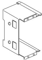
Installing this navigation system
Installation notes
- Do not install this navigation system in places where it may become subject to high temperatures or humidity, such as:
— Places close to a heater, vent or air conditioner.
— Places exposed to direct sunlight, such as on top of the dashboard.
— Places that may be splashed by rain, for example close to the door.
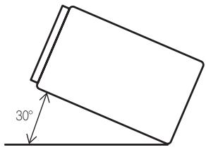
- Install this navigation system in an area strong enough to bear its weight. Choose a position where this navigation system can be firmly installed, and install it securely. If this navigation system is not securely installed, the current location of the vehicle cannot be displayed correctly.
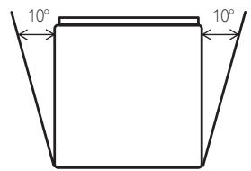
- Install the navigation unit horizontally on a surface within 0 degrees to 30 degrees tolerance (within 10 degrees to the left or right). Improper installation of the unit with the surface tilted more than these tolerances increases the potential for errors in the location display, and might otherwise cause reduced display performance.
text_image
30°
text_image
10°
10°
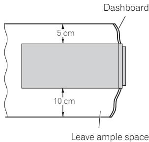
- When installing, to ensure proper heat dispersal when using this unit, make sure you leave ample space behind the rear panel and wrap any loose cables so they are not blocking the vents.
text_image
Dashboard
5 cm
10 cm
Leave ample space
- The semiconductor laser will be damaged if it overheats, so don't install the navigation unit anywhere hot —for instance, near a heater outlet.
- Do not install this navigation system where detaching the detachable device from the head unit is hampered by the gear stick or any other objects. Before installing this navigation system, be sure to leave sufficient space so that the detachable device does not prevent operation of the gear stick when it is detached. Otherwise, this may cause interference with the gear stick, or a malfunction of the detaching mechanism.
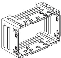
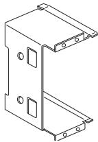
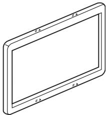
Parts supplied
- Parts marked (*1) are pre-installed.
- Parts marked (*2) are for in-store display use only.
natural_image
Line drawing of a microwave oven with control panel and buttons (no text or symbols)
The navigation unit
natural_image
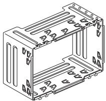
Technical line drawing of a multi-chamber electrical enclosure with mounting holes (no text or symbols)
Holder*1
natural_image
Technical line drawing of a mechanical bracket or housing (no text or symbols)
Side bracket*1 (2 pcs.)

Screw*1
(3 mm × 6 mm)
(8 pcs.)

Screw for fixing the side bracket*1 (5 mm × 6 mm) (4 pcs.)
natural_image
Isometric line drawing of a rectangular frame with rounded corners and a central blank space (no text or symbols)
Trim ring*1

Screw*2
(2 mm × 8 mm)
(1 pc.)
Before installing this navigation unit
1 Remove the trim ring.
Extend top and bottom of the trim ring outwards to remove the trim ring.
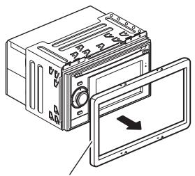
natural_image
Illustration of a device with a screen showing an arrow, no text or symbols present
Trim ring
2 Remove the holder.
Loosen the screws (3 mm × 6 mm) to remove the holder.
text_image
Holder
Screw (3 mm × 6 mm)
Installation with the holder and side bracket
1 Install the holder into the dashboard.
After inserting the holder into the dashboard, select and bend the tabs appropriate to the thickness of the dashboard material. (Install this navigation unit as firmly as possible using the top and bottom tabs. To secure this navigation unit, bend the tabs 90 degrees.)
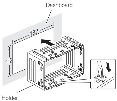
text_image
Dashboard
182
112
Holder
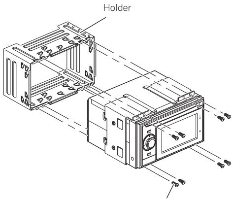
2 Install this navigation unit and fasten the screws.
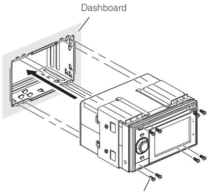
text_image
Dashboard
Screw (3 mm × 6 mm)
3 Attach the trim ring.
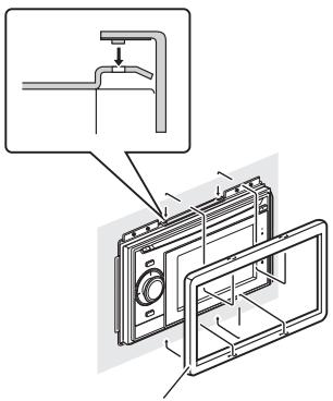
text_image
Technical diagram showing a mechanical assembly with labeled components and an inset view of a pipe connection.
Trim ring
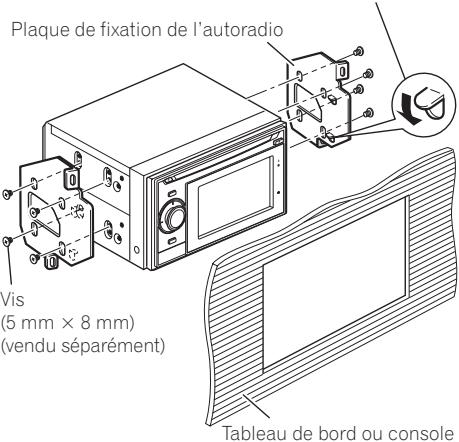
Installation using the screw holes on the side of the navigation unit
1 Remove the side brackets.
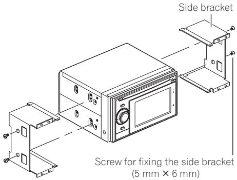
text_image
Side bracket
Screw for fixing the side bracket
(5 mm × 6 mm)
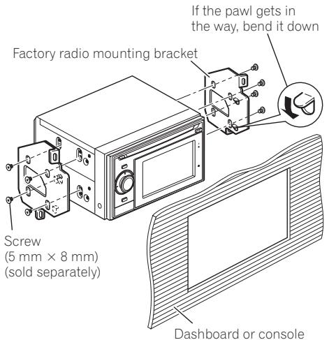
2 Fastening the navigation unit to the factory radio-mounting bracket.
Position the navigation unit so that its screw holes are aligned with the screw holes of the bracket, and tighten the screws at 3 or 4 locations on each side.
Use the screws (5 mm × 8 mm) (sold separately), depending on the shape of the bracket's screw holes.
natural_image
Simple line drawing of a two-panel device with four circular buttons and a handle (no text or symbols)
text_image
If the pawl gets in
the way, bend it down
Factory radio mounting bracket
Screw
(5 mm × 8 mm)
(sold separately)
Dashboard or console

Installing the GPS aerial

CAUTION
Do not cut the GPS aerial lead to shorten it or use an extension to make it longer. Altering the aerial cable could result in a short circuit or malfunction and permanent damage to the navigation system.
Installation notes
- The aerial should be installed on a level surface where radio waves will be blocked as little as possible. Radio waves cannot be received by the aerial if reception from the satellite is blocked.
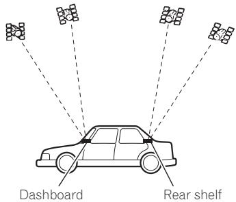
text_image
Dashboard
Rear shelf
- When installing the GPS aerial inside the vehicle, be sure to use the metal sheet provided with your system. If this is not used, the reception sensitivity will be poor.
- Do not cut the accessory metal sheet. This would reduce the sensitivity of the GPS aerial.
- Take care not to pull the aerial lead when removing the GPS aerial. The magnet attached to the aerial is very powerful, and the lead may become detached.
- Do not paint the GPS aerial, as this may affect its performance.
Parts supplied
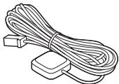
natural_image
Line drawing of a bundle of cables with connectors (no text or symbols)
GPS aerial

Metal sheet
When installing the aerial inside the vehicle (on the dashboard or rear shelf)

WARNING
Do not install the GPS aerial over any sensors or vents on the dashboard of the vehicle, as doing so may interfere with the proper functioning of such sensors or vents and may compromise the ability of the metal sheet under the GPS aerial to properly and securely affix to the dashboard.
Affix the metal sheet on as level a surface as possible where the GPS aerial faces the window. Place the GPS aerial on the metal sheet. (The GPS aerial is fastened with its magnet.)
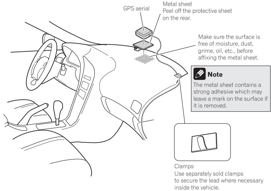
text_image
GPS aerial
Metal sheet
Peel off the protective sheet
on the rear.
Make sure the surface is
free of moisture, dust,
grime, oil, etc., before
affixing the metal sheet.
Note
The metal sheet contains a
strong adhesive which may
leave a mark on the surface if
it is removed.
Clamps
Use separately sold clamps
to secure the lead where necessary
inside the vehicle.

Notes
- When attaching the metal sheet, do not cut it into small pieces.
- Some models use window glass that does not allow signals from GPS satellites to pass through. On such models, install the GPS aerial on the outside of the vehicle.

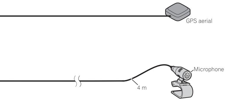
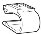
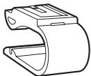
Installing the microphone
- Install the microphone in a place where its direction and distance from the driver make it easiest to pick up the driver's voice.
- Make sure to connect the microphone to the navigation system after the system is turned off. (ACC OFF)
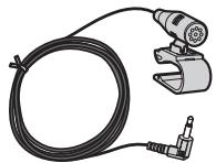
Parts supplied
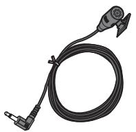
natural_image
Illustration of a black cable with a connector and terminal connector (no text or symbols)
Microphone
Microphone clip

Double-sided tape
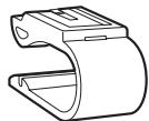
Mounting on the sun visor
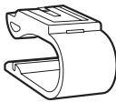
1 Install the microphone in the microphone clip.
Microphone clip
Microphone
natural_image
Technical line drawing of a handheld device with wires and a central component (no text or symbols)
2 Attach the microphone clip to the sun visor.

text_image
Microphone clip
Clamps
Use separately sold clamps to secure the lead where necessary inside the vehicle.
Install the microphone on the sun visor when it is in the up position. It cannot recognise the driver's voice if the sun visor is in the down position.
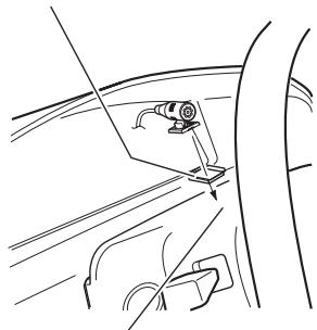
Installation on the steering column
- Mount the microphone on the steering column.
Double-sided tape
natural_image
Line drawing of a car interior showing a steering wheel and dashboard (no text or symbols)
Install the microphone on the steering column, keeping it away from the steering wheel.
natural_image
Line drawing of a car interior showing steering wheel and dashboard, with an inset showing a close-up of the dashboard (no text or symbols)
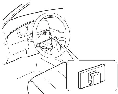
Clamps
Use separately sold clamps to secure the lead where necessary inside the vehicle.
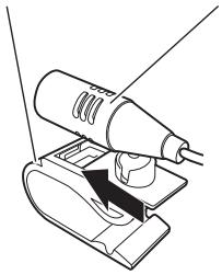
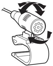
Adjusting the microphone angle
The microphone angle can be adjusted.
natural_image
Diagram of a plug-in connector with arrows indicating motion or force (no text or symbols)

After Installing this navigation system
1 Reconnecting the battery.
First, double-check that all connections are correct and that this product is installed correctly. Reassemble all vehicle components that you previously removed. Then reconnect the negative (−) cable to the negative (−) terminal of the battery.
2 Start the engine.
Press the RESET button on the navigation unit with a pointed object such as the tip of a pen.
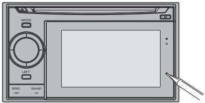
text_image
MODE
LIST
SPC
BAND
=497 011
4 Make the following settings.
For details concerning operations, refer to Operation Manual.
1 Set the language.
2 Drive an unobstructed road until the GPS starts receiving the signal normally.
3 Make some necessary adjustments.
- Setting the time
- Change other settings as you prefer

Note
After installing this navigation system, be sure to check at a safe place that the vehicle is performing normally.
natural_image
Illustration of a hand holding a battery with a switch and power plug (no text or symbols)

Para impedir daños

ADVERTENCIA
text_image
OFF ACC ON START
Posición ACC

text_image
OFF
ON START
Sin posición ACC
natural_image
Line drawing of a rectangular electronic device with ventilation slots and a control panel (no text or symbols)
natural_image
Pure electrical circuit lines without any symbols
natural_image
Line drawing of a coiled cable with two connectors (no text or symbols)
Antena GPS

natural_image
Illustration of a handheld tool with a coiled cable and connector (no text or symbols)
Micrófono

natural_image
Line drawing of a rectangular electronic device with ports and a control panel (no text or symbols)
natural_image
Isometric line drawing of a rectangular metal enclosure with internal slots and mounting holes (no text or symbols)
Soporte*1

natural_image
Technical line drawing of a metal bracket with mounting holes (no text or symbols)
natural_image
Isometric line drawing of a rectangular frame with rounded corners and a central blank space (no text or symbols)
Anillo embellecedor*1

Tornillo*2
(2 mm × 8 mm)
(1 pieza)
natural_image
Illustration of a device with a screen and an open panel, showing no text or symbols.
Anillo embellecedor
text_image
Technical diagram showing a mechanical assembly with an inset detail view of a pipe connection.
Anillo embellecedor
natural_image
Simple line drawing of a two-tiered device with four circular components and a handle (no text or symbols)
natural_image
Line drawing of a coiled cable with two connectors (no text or symbols)
Antena GPS

Hoja de metal
natural_image
Illustration of a black cable with a connector and a separate connector (no text or symbols)
Micrófono

Clip del micrófono

Cinta de doble cara
natural_image
Line drawing of a handheld electric shaver with a black cover, no text or symbols present
natural_image
Diagram of a car interior showing steering wheel, dashboard, and rearview mirror (no text or symbols)
natural_image
Line drawing of a car seatbelt with a valve inserted, showing no text or symbols
natural_image
Line drawing of a car interior showing steering wheel and dashboard, with an inset showing a switch device (no text or symbols)
natural_image
Diagram of a handheld electric vehicle with rotating buttons and wiring (no text or symbols)

text_image
MODE
LIFT
SRC BAND
=IF EX
natural_image
Illustration of a hand holding a battery with a switch and power plug, no text or symbols present

text_image
OFF ACC ON START
ACC-Stellung

text_image
OFF
ON
START
Keine ACC-Stellung
natural_image
Line drawing of a rectangular electronic device with ventilation grilles and a control panel (no text or symbols)
natural_image
Pure electrical circuit lines without any symbols
Netzkabel
RDS-TMC-Tuner
USB-Anschluss
natural_image
Line drawing of a coiled cable with two connectors (no text or symbols)
GPS-Antenne
natural_image
Illustration of a wire-coated tool with a mounted power tool and clamp (no text or symbols)
Mikrofon

text_image
30°
10°
10°
natural_image
Line drawing of a microwave oven with control panel and buttons (no text or symbols)
natural_image
Isometric line drawing of a multi-chamber electrical enclosure with mounting holes (no text or symbols)
Halterung*1

natural_image
Technical line drawing of a mechanical bracket or mounting plate (no text or symbols)
natural_image
Isometric line drawing of a rectangular frame with rounded corners and a central blank space (no text or symbols)
Abdeckring*1
natural_image
Illustration of a device with a screen and an open panel, showing no text or symbols.
Abdeckring
text_image
Technical diagram showing a mechanical assembly with an inset detail view of a pipe connection component.
Abdeckring
natural_image
Simple line drawing of a two-tier computer with four circular buttons and one open circle (no text or symbols)
natural_image
Line drawing of a coiled cable with two connectors (no text or symbols)
GPS-Antenne

Metallblech
natural_image
Illustration of a black cable with a connector and connector pin, no text or symbols present.
Mikrofon
Mikrofon-Clip
natural_image
Line drawing of a car interior showing a steering wheel and dashboard (no text or symbols)
natural_image
Line drawing of a car interior showing steering wheel and dashboard, with an inset showing a close-up of the dashboard (no text or symbols)
natural_image
Diagram of a handheld electric shaver with rotating arrows indicating motion (no text or symbols)

text_image
MODE
LIST
SRC BAND
=IFD 02
natural_image
Illustration of a hand inserting a battery into a terminal block with a plus and minus terminals (no text or symbols)

text_image
OFF ACC ON START
Position ACC

text_image
OFF
ON
START
Pas de position
ACC
natural_image
Line drawing of a rectangular electronic device with ventilation grilles and a control panel (no text or symbols)
Unité de navigation
natural_image
Pure electrical circuit lines without any symbols
natural_image
Line drawing of a coiled cable with two connectors (no text or symbols)
Antenne GPS

natural_image
Illustration of a tool with a coiled cable and a mechanical clamp (no text or symbols)
Microphone

text_image
Microphone
4 m
natural_image
Line drawing of a microwave oven with control panel and buttons (no text or symbols)
Unité de navigation
natural_image
Isometric line drawing of a rectangular metal enclosure with internal compartments and mounting holes (no text or symbols)
Support*1

natural_image
Isometric line drawing of a metal bracket with mounting holes and mounting holes (no text or symbols)
natural_image
Isometric line drawing of a rectangular frame with rounded edges and a blank center (no text or symbols)
natural_image
Illustration of a device with a screen showing an arrow, no text or symbols present
Anneau de garniture
2 Retirer le support.
text_image
Technical diagram showing a mechanical assembly with an inset detail view of a pipe connection.
Anneau de garniture
natural_image
Diagram of a device with four circular components and two vertical connectors, no text or symbols present
Si le cliquet ressort, le courber
natural_image
Line drawing of a coiled cable with two connectors (no text or symbols)
Antenne GPS

Plaque métallique
natural_image
Illustration of a black cable with a connector and a small attached plug (no text or symbols)
Microphone
Agrafe pour micro
natural_image
Line drawing of a handheld electric shaver with a circular base and cable, no text or symbols present
natural_image
Diagram of a car interior showing steering wheel, dashboard, and rearview mirror (no text or symbols)
natural_image
Line drawing of a car's seatbelt mechanism, showing no text or symbols
natural_image
Line drawing of a car interior showing steering wheel and dashboard, with an inset showing a switch device (no text or symbols)
natural_image
Diagram of a handheld device with rotating arrows indicating motion (no text or symbols)

text_image
MODE
LIST
SRC BAND
=87 52
natural_image
Illustration of a hand holding a battery with a switch and power plug (no text or symbols)

Per evitare danni

AVVERTENZA
text_image
OFF ACC ON START
Posizione ACC

text_image
OFF
ON
START
natural_image
Line drawing of a rectangular electronic device with ventilation grilles and a control panel (no text or symbols)
natural_image
Pure electrical circuit lines without any symbols
natural_image
Line drawing of a coiled cable with two connectors (no text or symbols)
Antenna GPS
natural_image
Illustration of a handheld electric shaver and cable with a clamp (no text or symbols)
Microfono

text_image
Technical diagram showing a mechanical device with labeled components and an inset magnified view of internal components.
Lato alimentato
Lato massa
natural_image
Line drawing of a rectangular electronic device with ports and a screen (no text or symbols)
natural_image
Isometric line drawing of a rectangular electronic enclosure with multiple slots and mounting holes (no text or symbols)
Supporto*1

natural_image
Technical line drawing of a metal bracket with mounting holes (no text or symbols)
Staffa laterale*1 (2 pezzi)

Vite*1 (3 mm × 6 mm)
(8 pezzi)

natural_image
Isometric line drawing of a rectangular frame with rounded corners and a flat top (no text or symbols)
natural_image
Illustration of a device with a screen and an open panel, showing no text or symbols.
cornice di finitura
text_image
Cruscotto
Vite (3 mm × 6 mm)
text_image
Technical diagram showing a mechanical assembly with an inset detail view of a pipe connection.
cornice di finitura
natural_image
Simple line drawing of a two-tiered device with four circular components and a handle (no text or symbols)
natural_image
Line drawing of a coiled cable with two connectors (no text or symbols)
Antenna GPS

Lastra metallica
natural_image
Illustration of a black cable with a connector and a small attached plug (no text or symbols)
Microfono
natural_image
Diagram of a car interior showing steering wheel, dashboard, and rearview mirror (no text or symbols)
natural_image
Line drawing of a car seatbelt with a valve inserted, showing no text or symbols
natural_image
Line drawing of a car interior showing steering wheel and dashboard, with an inset showing a switch device (no text or symbols)
natural_image
Diagram of a handheld electric shaver with arrows indicating motion (no text or symbols)

natural_image
Illustration of a hand holding a battery with a switch and power plug, no text or symbols present

text_image
OFF ACC ON START
ACC stand

text_image
OFF
ON
START
Geen ACC stand
natural_image
Line drawing of a rectangular electronic device with ventilation slots and a control panel (no text or symbols)
natural_image
Pure electrical circuit lines without any symbols
Stroomsnoer
RDS-TMC tuner
USB-stekker

natural_image
Line drawing of a coiled cable with two connectors (no text or symbols)
GPS-antenne
natural_image
Illustration of a tool with a coiled cable and a mechanical clamp (no text or symbols)
Microfoon

Aansluitingen
text_image
Technical diagram showing a mechanical device with labeled parts and an inset close-up of internal components.
Handremschakelaar

text_image
30°
10°
10°
text_image
Dashboard
5 cm
10 cm
natural_image
Line drawing of a rectangular electronic device with ports and a screen (no text or symbols)
natural_image
Technical line drawing of a rectangular electronic enclosure with mounting holes and internal compartments (no text or symbols)
Houder*1
natural_image
Isometric line drawing of a metal bracket with mounting holes and mounting holes (no text or symbols)
natural_image
Isometric line drawing of a rectangular frame with rounded corners and a flat top (no text or symbols)
Afwerkingsrand*1

Schroef*2
(2 mm × 8 mm)
(1 st.)
natural_image
Illustration of a device with a screen and an open panel, showing no text or symbols.
Afwerkingsrand
text_image
Dashboard
Schroef (3 mm × 6 mm)
text_image
Technical diagram showing a mechanical assembly with an inset detail view of a pipe connection.
Afwerkingsrand
natural_image
Simple line drawing of a two-tiered device with four circular components and a central dot (no text or symbols)
natural_image
Line drawing of a bundle of cables with connectors (no text or symbols)
GPS-antenne

Metalen plaatje
natural_image
Illustration of a black cable with a connector and a small attached plug (no text or symbols)
Microfoon
Microfoonklem

Dubbelzijdig tape
natural_image
Line drawing of a car interior showing a steering wheel and dashboard (no text or symbols)
natural_image
Line drawing of a car interior showing steering wheel and dashboard, with a close-up inset of the dashboard (no text or symbols)
natural_image
Illustration of a handheld device with a cable and connector, showing internal components and motion arrows (no text or symbols)

PIONEER ELECTRONICS (USA) INC.
P.O. Box 1540, Long Beach, California 90801-1540, U.S.A.
TEL: (800) 421-1404
PIONEER EUROPE NV
Haven 1087, Keetberglaan 1, B-9120 Melsele, Belgium/Belgique
TEL: (0) 3/570.05.11
Published by Pioneer Corporation.
Copyright © 2010 by Pioneer Corporation.
All rights reserved.