
DEH-P8400MP - Car stereo PIONEER - Free user manual and instructions
Find the device manual for free DEH-P8400MP PIONEER in PDF.

| Product type | Car stereo with CD/MP3 player |
| Brand | PIONEER |
| Model | DEH-P8400MP |
| Dimensions (W x H x D) | 182 x 53 x 160 mm (estimated) |
| Weight | Approximately 1.5 kg (estimated) |
| Power supply | 12 V DC, negative ground |
| Output power | 50 W max per channel (4 channels) |
| Speaker impedance | 4 to 8 ohms |
| Main features | CD/MP3 player, FM/AM radio tuner, IP-BUS input, preamp outputs front/rear/subwoofer, detachable faceplate, optional steering wheel remote control |
| Care and cleaning | Clean with a soft, dry cloth. Do not use solvents or abrasive products. |
| Safety | Do not expose to moisture. Use only recommended fuses. Professional installation recommended. |
| Spare parts | Detachable faceplate, extraction keys, mounting bracket, steering wheel remote control strap |
| Repairability | Have any repairs carried out by a qualified technician. |
| General information | Vehicles with 12 V battery and negative ground. Wire color codes conform to ISO standards. |
Frequently Asked Questions - DEH-P8400MP PIONEER
User questions about DEH-P8400MP PIONEER
0 question about this device. Answer the ones you know or ask your own.
Ask a new question about this device
Download the instructions for your Car stereo in PDF format for free! Find your manual DEH-P8400MP - PIONEER and take your electronic device back in hand. On this page are published all the documents necessary for the use of your device. DEH-P8400MP by PIONEER.
USER MANUAL DEH-P8400MP PIONEER
This product conforms to new cord colors.
Connecting the Units 1
Installation 5
Installation with the rubber bush 5
Removing the Unit 6
About the fixing screws for the front panel ..... 6
Installing the
Steering Remote Control Unit ...... 7
Installing the Unit on a
Left-Hand-Drive Car 8
Note:
- This unit is for vehicles with a 12-volt battery and negative grounding. Before installing it in a recreational vehicle, truck, or bus, check the battery voltage.
- To avoid shorts in the electrical system, be sure to disconnect the battery cable before beginning installation.
- Refer to the owner's manual for details on connecting the power amp and other units, then make connections correctly.
- Secure the wiring with cable clamps or adhesive tape. To protect the wiring, wrap adhesive tape around them where they lie against metal parts.
- Route and secure all wiring so it cannot touch any moving parts, such as the gear shift, handbrake, and seat rails. Do not route wiring in places that get hot, such as near the heater outlet. If the insulation of the wiring melts or gets torn, there is a danger of the wiring short-circuiting to the vehicle body.
- Don't pass the yellow lead through a hole into the engine compartment to connect to the battery. This will damage the lead insulation and cause a very dangerous short.
- Do not shorten any leads. If you do, the protection circuit may fail to work when it should.
- Never feed power to other equipment by cutting the insulation of the power supply lead of the unit and tapping into the lead. The current capacity of the lead will be exceeded, causing overheating.
- When replacing fuse, be sure to use only fuse of the rating prescribed on this unit.
-
Since a unique BPTL circuit is employed, never wire so the speaker leads are directly grounded or the left and right speaker leads are common.
-
Speakers connected to this unit must be high-power types with minimum rating of 50 W and impedance of 4 to 8 ohms. Connecting speakers with output and/or impedance values other than those noted here may result in the speakers catching fire, emitting smoke, or becoming damaged.
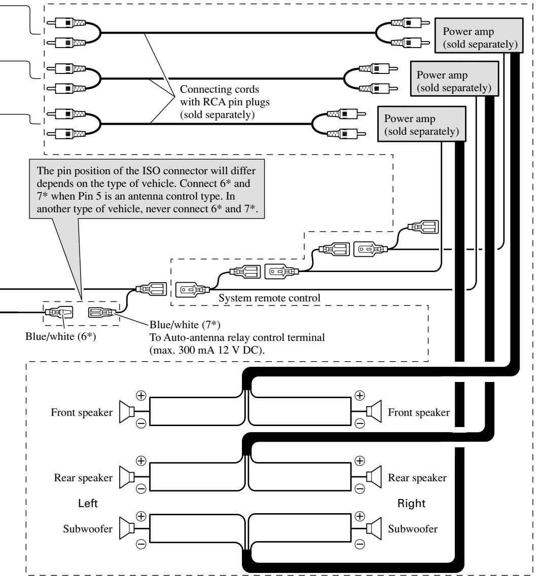
- When this product's source is switched ON, a control signal is output through the blue/white lead. Connect to an external power amp's system remote control or the car's Auto-antenna relay control terminal (max. 300 mA 12 V DC). If the car features a glass antenna, connect to the antenna booster power supply terminal.
- When an external power amp is being used with this system, be sure not to connect the blue/white lead to the amp's power terminal. Likewise, do not connect the blue/white lead to the power terminal of the auto-antenna. Such connection could cause excessive current drain and malfunction.
- To avoid short-circuiting, cover the disconnected lead with insulating tape. Especially, insulate the unused speaker leads without fail. There is a possibility of short-circuiting if the leads are not insulated.
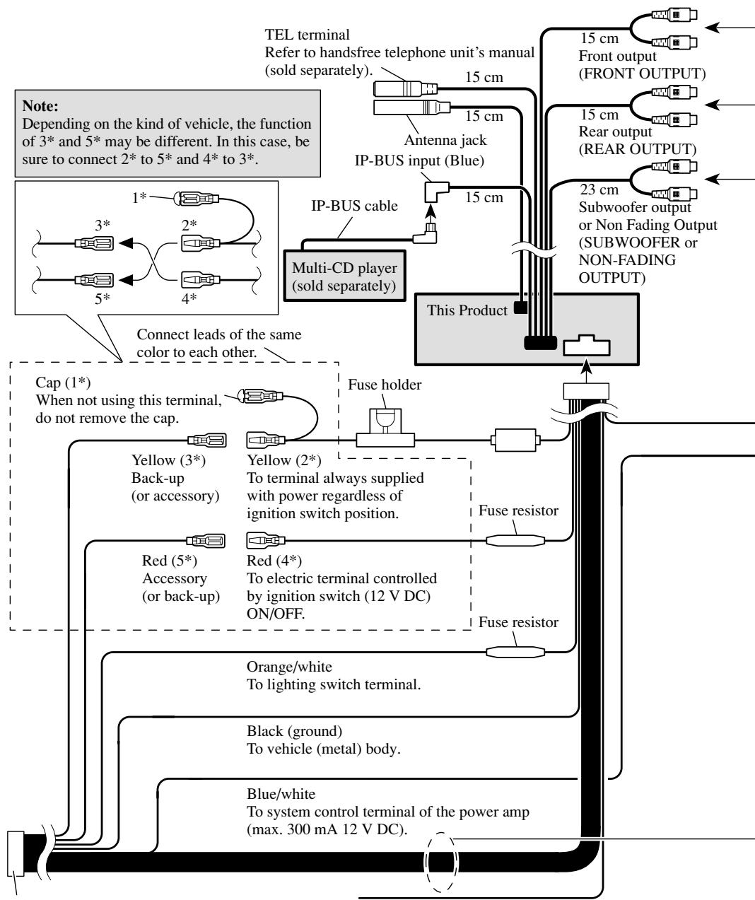
- To prevent incorrect connection, the input side of the IP-BUS connector is blue, and the output side is black. Connect the connectors of the same colors correctly.
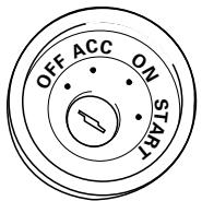
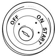
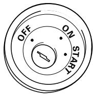
- If this unit is installed in a vehicle that does not have an ACC (accessory) position on the ignition switch, the red lead of the unit should be connected to a terminal coupled with ignition switch ON/OFF operations. If this is not done, the vehicle battery may be drained when you are away from the vehicle for several hours. (Fig. 1)
text_image
OFF ACC ON STARTACC position
text_image
OFF ON STARTNo ACC position
Fig. 1
- The black lead is ground. Please ground this lead separately from the ground of high-current products such as power amps.
If you ground the products together and the ground becomes detached, there is a risk of damage to the products or fire.
- Cords for this product and those for other products may be different colors even if they have the same function. When connecting this product to another product, refer to the supplied Installation manuals of both products and connect cords that have the same function.
flowchart
graph TD
    A["TEL terminal\nRefer to handsfree telephone unit's manual (sold separately)."] --> B["15 cm Antenna jack\nIP-BUS input (Blue)"]
    B --> C["Multi-CD player (sold separately)"]
    C --> D["This Product"]
    D --> E["Front output (FRONT OUTPUT)"]
    D --> F["Rear output (REAR OUTPUT)"]
    D --> G["Subwoofer output or Non Fading Output (SUBWOOFER or NON-FADING OUTPUT)"]
    H["Cap (1*)\nWhen not using this terminal,\ndo not remove the cap."] --> I["Fuse holder"]
    I --> J["Fuse resistor"]
    I --> K["Fuse resistor"]
    L["Yellow (3*)\nBack-up (or accessory)"] --> M["Yellow (2*)\nTo terminal always supplied with power regardless of ignition switch position."]
    N["Red (5*)\nAccessory (or back-up)"] --> O["Red (4*)\nTo electric terminal controlled by ignition switch (12 V DC) ON/OFF."]
    P["Orange/white\nTo lighting switch terminal."] --> Q["Fuse resistor"]
    R["Black (ground)\nTo vehicle (metal) body."] --> S["Fuse resistor"]
    T["Blue/white\nTo system control terminal of the power amp (max. 300 mA 12 V DC)."] --> U["Fuse resistor"]
    V["15 cm"] --> W["15 cm Front output (FRONT OUTPUT)"]
    X["15 cm"] --> Y["15 cm Rear output (REAR OUTPUT)"]
    Z["23 cm"] --> AA["Subwoofer output or Non Fading Output (SUBWOOFER or NON-FADING OUTPUT)"]
ISO connector
Note:
In some vehicles, the ISO connector may be divided into two. In this case, be sure to connect to both connectors.
Yellow/black
If you use a cellular telephone, connect it via the Audio Mute lead on the cellular telephone. If not, keep the Audio Mute lead free of any connections.
flowchart
graph TD
    A["Pin 5"] --> B["Connecting cords with RCA pin plugs (sold separately)"]
    B --> C["Power amp (sold separately)"]
    C --> D["Power amp (sold separately)"]
    D --> E["Blue/white (6*)"]
    E --> F["System remote control"]
    F --> G["Front speaker"]
    F --> H["Rear speaker"]
    F --> I["Subwoofer"]
    G --> J["Front speaker"]
    H --> K["Rear speaker"]
    I --> L["Subwoofer"]
    style A fill:#f9f,stroke:#333
    style B fill:#f9f,stroke:#333
    style C fill:#ccf,stroke:#333
    style D fill:#ccf,stroke:#333
    style E fill:#dfd,stroke:#333
    style F fill:#dfd,stroke:#333
    style G fill:#dfd,stroke:#333
    style H fill:#dfd,stroke:#333
    style I fill:#dfd,stroke:#333
    style J fill:#dfd,stroke:#333
    style K fill:#dfd,stroke:#333
    style L fill:#dfd,stroke:#333
Speaker leads
White : Front left ⊕
White/black : Front left ⊖
Gray : Front right ⊕
Gray/black : Front right ⊖
Green : Rear left ⊕ or Subwoofer ⊕
Green/black: Rear left ⊖ or Subwoofer ⊖
Violet : Rear right ⊕ or Subwoofer ⊕
Violet/black: Rear right ⊖ or Subwoofer ⊖
Use this for connections when you have the separately available amplifier.
Note:
Change the Initial Setting of this Product (refer to the Operation Manual). The subwoofer output of this unit is monaural.
Fig. 2
Note:
- Before finally installing the unit, connect the wiring temporarily, making sure it is all connected up properly, and the unit and the system work properly.
- Use only the parts included with the unit to ensure proper installation. The use of unauthorized parts can cause malfunctions.
- Consult with your nearest dealer if installation requires the drilling of holes or other modifications of the vehicle.
- Install the unit where it does not get in the driver's way and cannot injure the passenger if there is a sudden stop, like an emergency stop.
- The semiconductor laser will be damaged if it overheats, so don't install the unit anywhere hot — for instance, near a heater outlet.
- If installation angle exceeds 60^ from horizontal, the unit might not give its optimum performance. (Fig. 3)
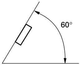
text_image
60°Fig. 3
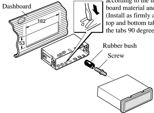
Installation with the rubber bush
text_image
Dashboard 182 53 according to the top board material and (Install as firmly a top and bottom tab the tabs 90 degree) Rubber bush ScrewHolder
After inserting the holder into the dashboard, then select the appropriate tabs according to the thickness of the dashboard material and bend them.
(Install as firmly as possible using the top and bottom tabs. To secure, bend the tabs 90 degrees.)
Fig. 4
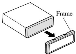
text_image
FramePull out to remove the frame.
(When reattaching the frame, point the side with a groove downwards and attach it.)
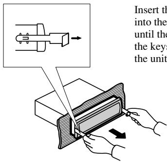
text_image
Insert the into the until the the keys the unitInsert the supplied extraction keys into the unit, as shown in the figure, until they click into place. Keeping the keys pressed against the sides of the unit, pull the unit out.
Fig. 5
About the fixing screws for the front panel
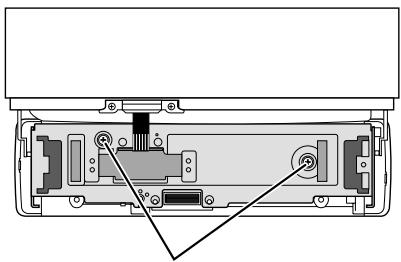
natural_image
Technical diagram of a device rear panel showing internal components and mounting points (no text or labels)Fixing screw
If you do not operate the Detaching and Replacing the Front Panel Function, use the supplied fixing screws and fix the front panel to this unit.
Fig. 6
WARNING
- Avoid installing this unit in such a location where the operation of safety devices such as airbags is prevented by this unit. Otherwise, there is a danger of a fatal accident.
- Avoid installing this unit in such a location where the operation of the steering wheel and the gearshift lever may be prevented. Otherwise, it may result in a traffic accident.
CAUTION
- Installation of this unit requires specialized skills and experience. Installation of this unit should be entrusted to a dealer from whom you purchased this unit.
- Install this unit using only the parts supplied with this unit. If other parts are used, this unit may be damaged or could dismount itself, which leads to an accident or trouble.
• Install this unit as required by this manual. Failure to do so may cause an accident. - Do not install this unit near the doors where rainwater is likely to be spilled on the unit. Incursion of water into the unit may cause smoke or fire.
⚠ WARNING
- Fix this unit securely to the steering wheel with the belt attached to the unit. If this unit is loose, it disturbs driving stability, which may result in a traffic accident.
- Do not attach this unit to the outer circumference of the steering wheel. Otherwise, it disturbs driving stability, causing a traffic accident. Always attach this unit to the inner circumference of the steering wheel as shown. (Fig. 7)
Note:
- Do not install this unit in such a place as may obstruct the driver's view.
- Since interior layout differs depending on the type of vehicle, the ideal installation location for the unit also differs. When installing the unit, select a location that assures optimum transmission of signals from the unit to the car stereo.
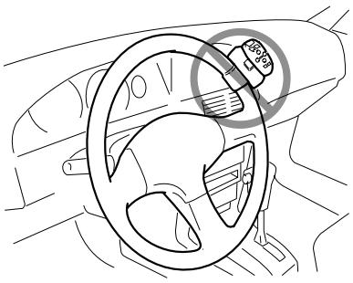
natural_image
Line drawing of a car interior showing steering wheel and dashboard (no text or symbols)
natural_image
Line drawing of a car interior showing steering wheel and dashboard (no text or symbols)Fig. 7
Installing the Unit on a Left-Hand-Drive Car
Note:
- When the unit is installed on a right-hand-drive car, the horizontal positions are inverted.
1. Secure inner holder to the inner circumference of the steering wheel with belt. (Fig. 8)
- Fit the inner holder to the steering wheel so that the arrow-marked side faces the driver as shown below.
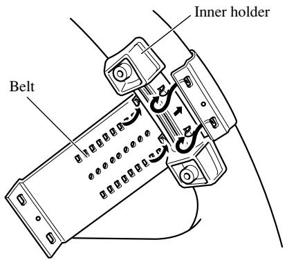
text_image
Inner holder BeltFig. 8
2. Cut the extra portion of the belt at the center of the inner holder.
(Fig. 9)
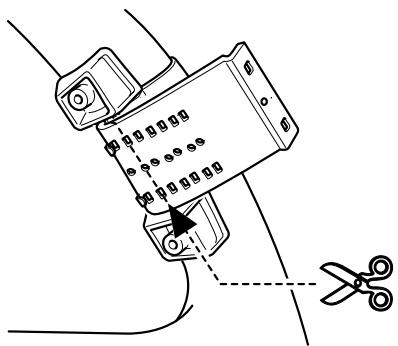
natural_image
Technical line drawing of a mechanical assembly with scissors cutting through a bracket (no text or symbols)Fig. 9
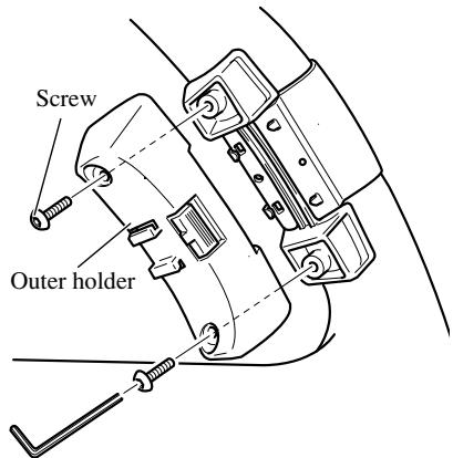
3. Install outer holder on the inner holder and secure with screws. (Fig. 10)
- Tighten the screws with the supplied hexagonal wrench.
text_image
Screw Outer holderFig. 10
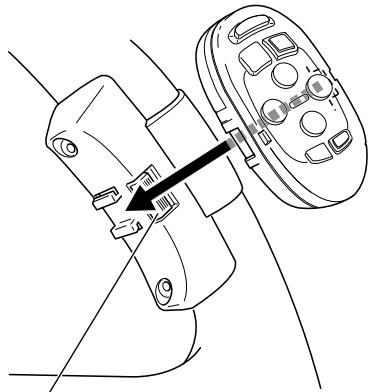
4. Install the remote control unit in the holder. (Fig. 11)
- When removing the remote control unit from the holder, move the corrugated release section toward the steering wheel and slide the remote control unit toward you.
natural_image
Technical line drawing of a mechanical assembly with a directional arrow indicating movement (no text or symbols)Release Section
Fig. 11
text_image
OFF ACC ON STARTPosición ACC
text_image
OFF ON STARTnatural_image
Technical diagram of a device rear panel showing internal components and mounting points (no text or labels)natural_image
Line drawing of a car interior showing steering wheel and dashboard (no text or symbols)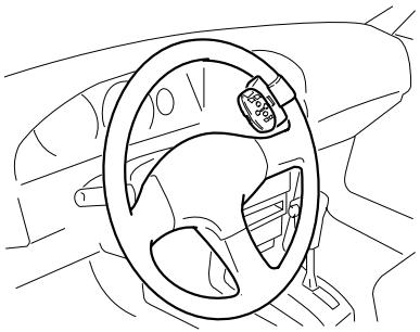
natural_image
Line drawing of a car interior showing steering wheel and dashboard (no text or symbols)Fig. 7
natural_image
Technical line drawing of a mechanical clamp or bracket with a pair of scissors cutting the part (no text or symbols present)Fig. 9
natural_image
Technical line drawing of a mechanical assembly with a bracket and housing (no text or symbols)text_image
OFF ACC ON STARTACC-Position

text_image
OFF ON STARTKeine ACC-Position
Abb. 1
natural_image
Technical diagram of a device rear panel showing internal components and mounting points (no text or labels)natural_image
Line drawing of a car interior showing steering wheel and dashboard (no text or symbols)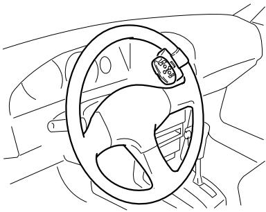
natural_image
Line drawing of a car steering wheel and dashboard (no text or symbols)Abb. 7
text_image
Technical diagram showing a mechanical assembly with labeled parts and a scissors cutting the part, likely illustrating a machining or disassembly process.Abb. 9
natural_image
Technical line drawing of a mechanical component with an arrow indicating assembly or adjustment (no text or symbols present)text_image
OFF ACC ON STARTPosition ACC

text_image
OFF ON STARTAucune position ACC
Fig. 1
natural_image
Technical diagram of a device rear panel showing internal components and mounting points (no text or labels)Vis de fixation
natural_image
Line drawing of a car interior showing steering wheel and dashboard (no text or symbols)
natural_image
Line drawing of a car interior showing steering wheel and dashboard (no text or symbols)Fig. 7
text_image
Technical diagram showing a mechanical assembly with labeled parts and a scissors cutting operation indicated by dashed lines.Fig. 9
text_image
Vis Support externeFig. 10
natural_image
Technical line drawing of a mechanical assembly with a black arrow indicating a component (no text or symbols present)text_image
OFF ACC ON START
text_image
OFF ON STARTnatural_image
Technical diagram of a device rear panel showing internal components and mounting points (no text or labels)Vite di fissaggio
natural_image
Line drawing of a car interior showing steering wheel and dashboard (no text or symbols)
natural_image
Line drawing of a car interior showing steering wheel and dashboard (no text or symbols)Fig. 7
text_image
Technical diagram showing a mechanical assembly with labeled parts and a scissors cutting operationFig. 9
natural_image
Technical line drawing of a mechanical assembly with a black arrow indicating a component (no text or symbols present)text_image
OFF ACC ON STARTACC stand

text_image
OFF ON STARTGeen ACC stand
Afb. 1
natural_image
Technical diagram of a device rear panel showing internal components and mounting points (no text or labels)Bevestigingsschroef
natural_image
Interior view of a car showing steering wheel and dashboard (no text or symbols)
natural_image
Line drawing of a car interior showing steering wheel and dashboard (no text or symbols)Afb. 7
natural_image
Technical line drawing of a mechanical clamp or bracket with a pair of scissors cutting the part (no text or symbols present)Afb. 9
natural_image
Technical line drawing of a mechanical assembly with a black arrow indicating a component (no text or symbols present)PIONEER ELECTRONICS (USA) INC.
P.O. Box 1540, Long Beach, California 90801-1540, U.S.A.
TEL: (800) 421-1404
PIONEER EUROPE NV
Haven 1087, Keetberglaan 1, B-9120 Melsele, Belgium
TEL: (0) 3/570.05.11
PIONEER ELECTRONICS ASIACENTRE PTE. LTD.
253 Alexandra Road, #04-01, Singapore 159936
TEL: 65-472-1111
PIONEER ELECTRONICS AUSTRALIA PTY. LTD.
178-184 Boundary Road, Braeside, Victoria 3195, Australia
TEL: (03) 9586-6300
PIONEER ELECTRONICS OF CANADA, INC.
300 Allstate Parkway, Markham, Ontario L3R OP2, Canada
TEL: (905) 479-4411
PIONEER ELECTRONICS DE MEXICO, S.A. de C.V.
San Lorenzo 1009 3er. Piso Desp. 302
Col. Del Valle Mexico, D.F. C.P. 03100
TEL: 5-688-52-90
Published by Pioneer Corporation.
Copyright © 2001 by Pioneer Corporation.
All rights reserved.
Publication de Pioneer Corporation.
Copyright © 2001 Pioneer Corporation.