USER MANUAL AVH-P6400CD PIONEER
This product conforms to new cord colors.
Connecting the Units 1
Connecting the power cord (1) 3
Connecting the power cord (2) 5
Connecting the system (A) 6
Connecting the system (B) 7
VIDEO Input / Output Connection 8
Attaching the Noise Filters 8
Installation 9
DIN Front/Rear-mount 9
DIN Front-mount 9
DIN Rear-mount 11
CAUTION
- PIONEER does not recommend that you install or service your display yourself. Installing or servicing the product may expose you to risk of electric shock or other hazards. Refer all installation and servicing of your display to authorized Pioneer service personnel.
- Secure all wiring with cable clamps or electrical tape. Do not allow any bare wiring to remain exposed.
- Do not drill a hole into the engine compartment to connect the yellow lead of the unit to the vehicle battery. Engine vibration may eventually cause the insulation to fail at the point where the wire passes from the passenger compartment into the engine compartment. Take extra care in securing the wire at this point.
- It is extremely dangerous to allow the display lead to become wound around the steering column or gearshift. Be sure to install the display in such a way that it will not obstruct driving.
- Make sure that wires will not interfere with moving parts of the vehicle, such as the gearshift, parking brake or seat sliding mechanism.
- Do not shorten any leads. If you do, the protection circuit may fail to work properly.
Note:
- This unit is for vehicles with a 12-volt battery and negative grounding. Before installing it in a recreational vehicle, truck, or bus, check the battery voltage.
- To avoid shorts in the electrical system, be sure to disconnect the battery cable before beginning installation.
Refer to the owner's manual for details on connecting the power amp and other units, then make connections correctly.
- Secure the wiring with cable clamps or adhesive tape. To protect the wiring, wrap adhesive tape around them where they lie against metal parts.
- Route and secure all wiring so it cannot touch any moving parts, such as the gear shift, handbrake, and seat rails. Do not route wiring in places that get hot, such as near the heater outlet. If the insulation of the wiring melts or gets torn, there is a danger of the wiring short-circuiting to the vehicle body.
- Don't pass the yellow lead through a hole into the engine compartment to connect to the battery. This will damage the lead insulation and cause a very dangerous short.
- Do not shorten any leads. If you do, the protection circuit may fail to work when it should.
- Never feed power to other equipment by cutting the insulation of the power supply lead of the unit and tapping into the lead. The current capacity of the lead will be exceeded, causing overheating.
- When replacing fuse, be sure to use only fuse of the rating prescribed on the fuse holder.
- Since a unique BPTL circuit is employed, never wire so the speaker leads are directly grounded or the left and right speaker leads are common.
- If the RCA pin jack on the unit will not be used, do not remove the caps attached to the end of the connector.
- Speakers connected to this unit must be high-power types with minimum rating of 50W and impedance of 4 to 8 ohms. Connecting speakers with output and/or impedance values other than those noted here may result in the speakers catching fire, emitting smoke, or becoming damaged.
-
When this product's source is switched ON, a control signal is output through the blue/white lead. Connect to an external power amp's system remote control or the car's Auto-antenna relay control terminal (max. 300mA12VDC ). If the car features a glass antenna, connect to the antenna booster power supply terminal.
-
When an external power amp is being used with this system, be sure not to connect the blue/white lead to the amp's power terminal. Likewise, do not connect the blue/white lead to the power terminal of the auto-antenna. Such connection could cause excessive current drain and malfunction.
- To avoid short-circuiting, cover the disconnected lead with insulating tape. Especially, insulate the nused speaker leads without fail. There is a possibility of short-circuiting if the leads are not insulated.
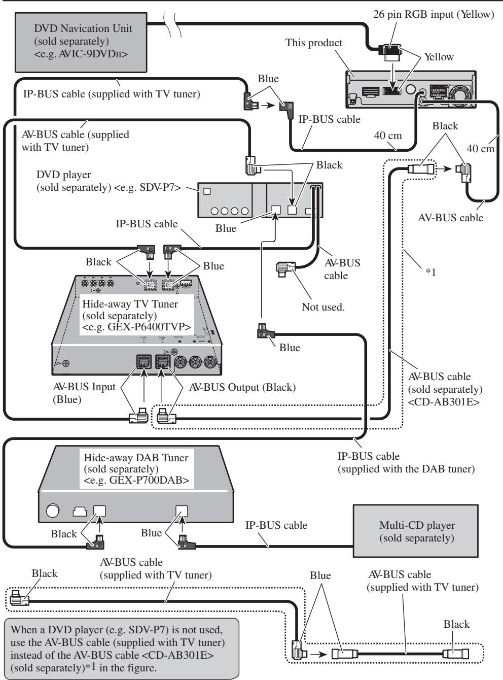
- To prevent incorrect connection, the input side of the IP-BUS connector is blue, and the output side is black. Connect the connectors of the same colors correctly.
- If this unit is installed in a vehicle that does not have an ACC (accessory) position on the ignition switch, the red lead of the unit should be connected to a terminal coupled with ignition switch ON/OFF operations. If this is not done, the vehicle battery may be drained when you are away from the vehicle for several hours. (Fig.1)
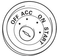
ACC position
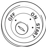
No ACC position
Fig. 1
- The black lead is ground. Please ground this lead separately from the ground of high-current products such as power amps. If you ground the products together and the ground becomes detached, there is a risk of damage to the products or fire.
- Cords for this product and those for other products may be different colors even if they have the same function. When connecting this product to another product, refer to the supplied Installation manuals of both products and connect cords that have the same function.
Connecting the power cord (1)
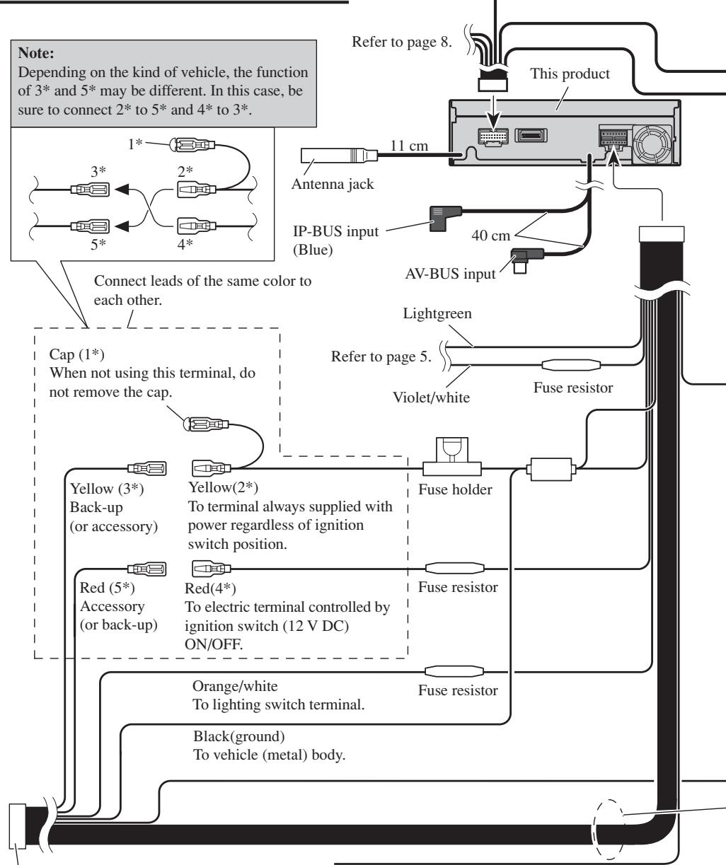
ISO connector
Note:
In some vehicles, the ISO connector may be divided into two. In this case, be sure to connect to both connectors.
Yellow/black
If you use a cellular telephone, connect it via the Audio Mute lead on the cellular telephone. If not, keep the Audio Mute lead free of any connections.
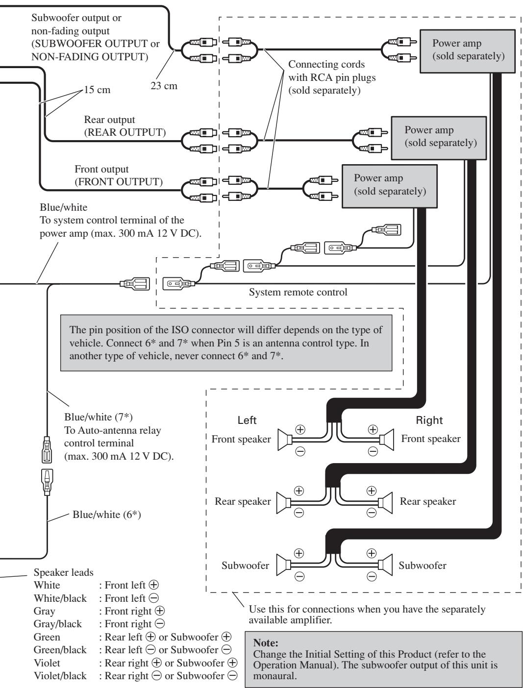
Fig. 2
Connecting the power cord (2)
When using this product with a back-up camera, automatic switching to VIDEO video when the gear shift is moved to the REVERSE (R) position is possible.
Connect the back-up camera to the VIDEO input.
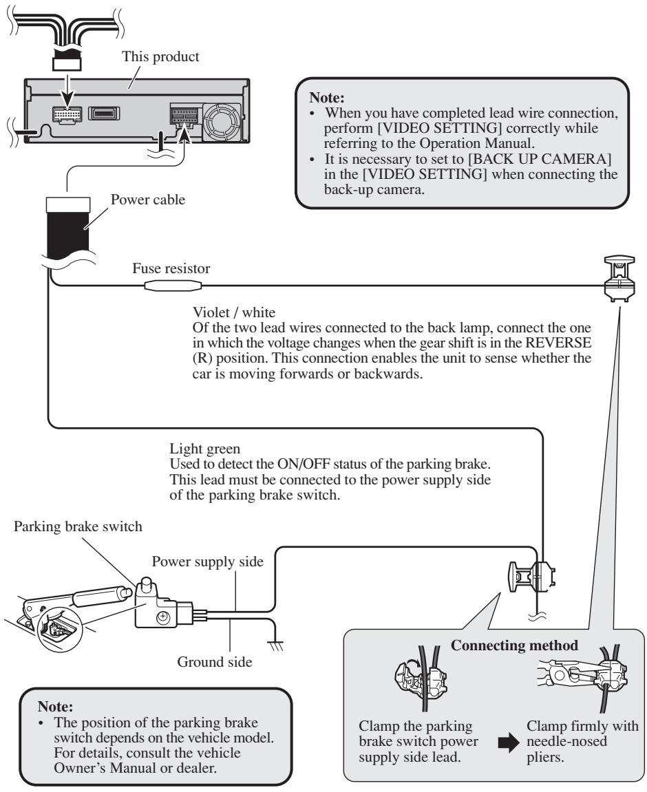
Fig. 3
Connecting the system (A)
Fig. 4
Perform [VIDEO SETTING] correctly while referring to the Operation Manual.
Connecting the system (B)

Fig. 5
Perform [VIDEO SETTING] correctly while referring to the Operation Manual.
When connecting an XDV-P9II, refer to the XDV-P9II's Owner's manual.
Fig. 6
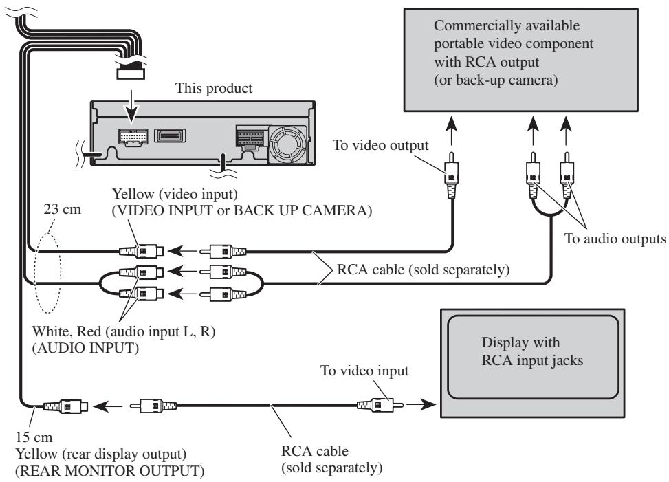
Perform [VIDEO SETTING] correctly while referring to the Operation Manual.
Attaching the Noise Filters
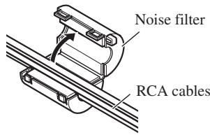
1.
To prevent the noise, use the supplied noise filters correctly.
- Remove the noise filter from the cords.
- Attach the noise filters and lock ties as illustrated.
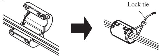
2.
Fig. 7
Note:
- Before finally installing the unit, connect the wiring temporarily, making sure it is all connected up properly, and the unit and the system work properly.
- Use only the parts included with the unit to ensure proper installation. The use of unauthorized parts can cause malfunctions.
- Consult with your nearest dealer if installation requires the drilling of holes or other modifications of the vehicle.
- Install the unit where it does not get in the driver's way and cannot injure the passenger if there is a sudden stop, like an emergency stop.
- Do not place the display in a position where it will impede the driver's visibility or affect the operation of your vehicle's air bags.
-
The semiconductor laser will be damaged if it overheats, so don't install the unit anywhere hot — for instance, near a heater outlet.
-
If installation angle exceeds 30^ from horizontal, the unit might not give its optimum performance. (Fig. 8)
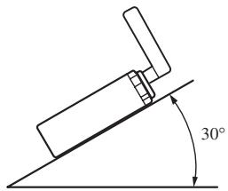
Fig. 8
DIN Front/Rear-mount
This unit can be properly installed either from "Front" (conventional DIN Front-mount) or "Rear" (DIN Rear-mount installation, utilizing threaded screw holes at the sides of unit chassis). For details, refer to the following illustrated installation methods.
DIN Front-mount
Installation with the rubber bush
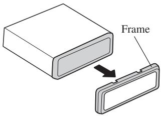
1. Remove the frame. (Fig. 9)
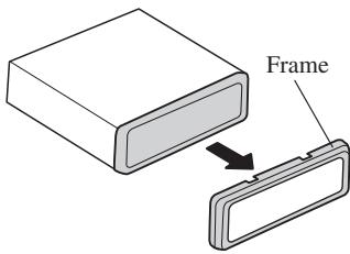
Fig. 9
Pull out to remove the frame. (When reattaching the frame, point the side with a groove downwards and attach it.)
2. Install side brackets. (Fig. 10)
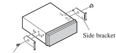
Flush surface screw (5× 6mm)
Fig. 10
3. Fastening the unit. (Fig. 11)
As a rule, secure with side brackets (large).
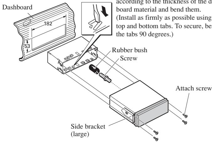
Holder
After inserting the holder into the dashboard, then select the appropriate tabs according to the thickness of the dashboard material and bend them.
(Install as firmly as possible using the top and bottom tabs. To secure, bend the tabs 90 degrees.)
Fig. 11
When the installation space is not very deep
When installing in a shallow space, secure with side brackets (small). In this case, stick conceal tape on parts that protrude from the dashboard.
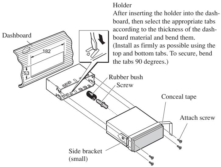
Fig. 12
DIN Rear-mount
Installation using the screw holes on the side of the unit
1. Remove the frame. (Fig. 13)
Fig. 13
Pull out to remove the frame. (When reattaching the frame, point the side with a groove downwards and attach it.)
2. Fastening the unit to the factory radio mounting bracket. (Fig. 14) (Fig. 15)
Select a position where the screw holes of the bracket and the screw holes of this product become aligned (are fitted), and tighten the screws at 2 places on each side. Use any of binding screws (4× 3mm) , binding screws (5× 6mm) or flush surface screws (5× 6mm) , depending on the shape of the screw holes in the bracket.
*1 Use binding screws (4 × 3 mm) only.
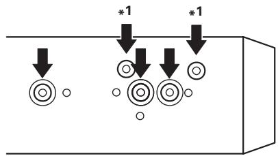
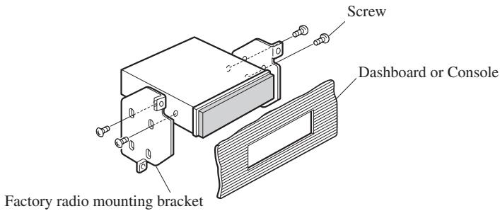
Fig. 14
Fig. 15
PIONEER ELECTRONICS (USA) INC.
P.O. Box 1540, Long Beach, California 90801-1540, U.S.A.
TEL: (800) 421-1404
PIONEER EUROPE NV
Haven 1087, Keetberglaan 1, B-9120 Melsele, Belgium
TEL: (0) 3/570.05.11
PIONEER ELECTRONICS ASIACENTRE PTE. LTD.
253 Alexandra Road, #04-01, Singapore 159936
TEL: 65-6472-1111
PIONEER ELECTRONICS AUSTRALIA PTY. LTD.
178-184 Boundary Road, Braeside, Victoria 3195, Australia
TEL: (03) 9586-6300
PIONEER ELECTRONICS OF CANADA, INC.
300 Allstate Parkway, Markham, Ontario L3R OP2, Canada
TEL: (905) 479-4411
PIONEER ELECTRONICS DE MEXICO, S.A. de C.V.
San Lorenzo 1009 3er. Piso Desp. 302
Col. Del Valle Mexico, D.F. C.P. 03100
TEL: 55-5688-52-90
Published by Pioneer Corporation.
Copyright © 2002 by Pioneer Corporation.
All rights reserved.
Publication de Pioneer Corporation.
Copyright © 2002 Pioneer Corporation.