
IAN 291871 - Table POWERFIX - Free user manual and instructions
Find the device manual for free IAN 291871 POWERFIX in PDF.


User questions about IAN 291871 POWERFIX
0 question about this device. Answer the ones you know or ask your own.
Ask a new question about this device
Download the instructions for your Table in PDF format for free! Find your manual IAN 291871 - POWERFIX and take your electronic device back in hand. On this page are published all the documents necessary for the use of your device. IAN 291871 by POWERFIX.
USER MANUAL IAN 291871 POWERFIX
Installation and safety precautions
DK
ARBEJDS- OG
OPSPÆNDINGSBORD
natural_image
Technical line drawing of a mechanical assembly with two views: one showing a bolted support structure and another showing a close-up of a bolted component (no text or symbols present)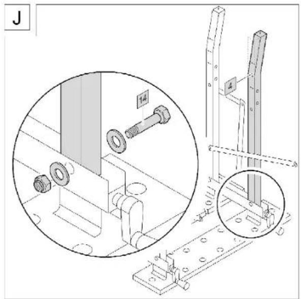
text_image
J 1.4 4 0 1 2 3 4 5 6 7 8 9 10 11 12 13 14 15 16 17 18 19 20 21 22 23 24 25 26 27 28 29 30 31 32 33 34 35 36 37 38 39 40 41 42 43 44 45 46 47 48 49 50 51 52 53 54 55 56 57 58 59 60 61 62 63 64 65 66 67 68 69 70 71 72 73 74 75 76 77 78 79 80 81 82 83 84 85 86 87 88 89 90 91 92 93 94 95 96 97 98 99 X: X1, Y: X2, Z: Z3, A: A4, B: B5, C: C6, D: D7, E: E8, F: F9, G: G10, H: H11, I: I2, J: I3, K: I4, L: I5, M: I6, N: I7, O: I8, P: P1, Q: Q2, R: R3, S: S4, T: T5, U: U6, V: U7, W: W8, X: X9, Y: X10, Z: Z1, A: A2, B: A3, C: A4, D: A5, E: A6, F: A7, G: A8, H: H9, I: I0, J: I1, K: I2, L: I3, M: I4, N: I5, O: I6, P: P7, Q: Q8, R: R9, S: S10, T: T11, U: U12, V: U13, W: U14, X: X15, Y: X16, Z: X17, A: A2, B: A3, C: A4, D: A5, E: A6, F: A7, G: A8, H: A9, I: I0, J: I1, K: I2, L: I3, M: I4, N: I5, O: I6, P: I7, Q: I8, R: I9, S: S10, T: T11, U: U12, V: U13, W: U14, X: U15, Y: U16, Z: U17, A: A2, B: A3, C: A4, D: A5, E: A6, F: A7, G: A8, H: A9, I: I0, J: I1, K: I2, L: I3, M: I4, N: I5, O: I6, P: I7, Q: I8, R: I9, S: S10, X: X11, Y: X12, Z: X13, A: A2, B: A3, C: A4, D: A5, E: A6, F: A7, G: A8, H: A9, I: I0, J: I1, K: I2, L: I3, M: I4, N: I5, O: I6, P: I7, Q: I8, R: I9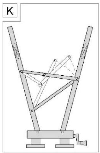
natural_image
Mechanical linkage diagram with labeled component K, showing two vertical supports and a central frame (no text or symbols beyond label)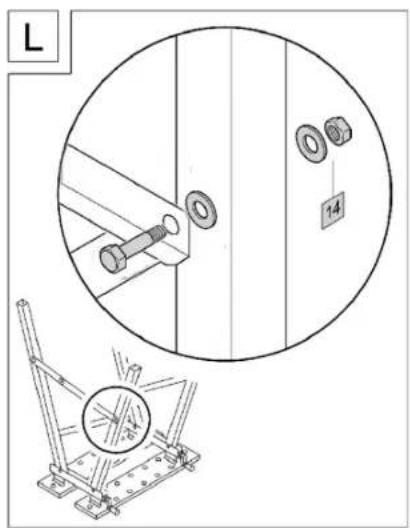
text_image
L 14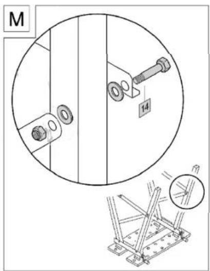
text_image
M 14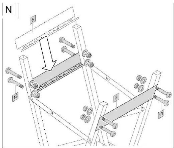
text_image
N 8 13 6 13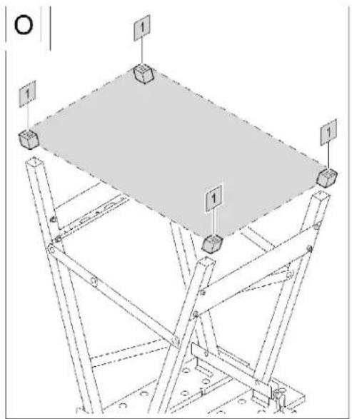
natural_image
Technical line drawing of a structural frame with supports and labeled components (no text or symbols)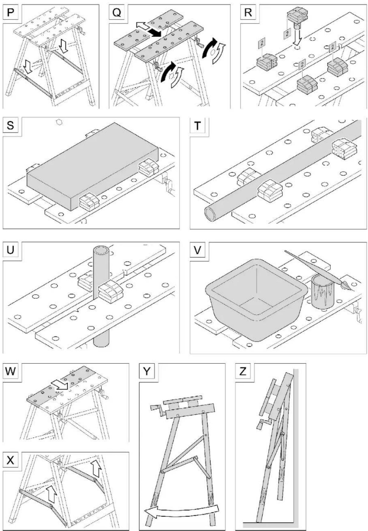

Legend for the used pictograms
| Legend for the used pictograms | |||
 | Read the installation instructions! |  | Quick set-up |
| Observe the warnings and safety precautions! | Maximum payload 100 kg | ||
| Dispose packaging and product in an environmentally friendly way! | VPA quality checked | ||
Introduction
Congratulations on your purchase. Before installation and initial operation, familiarise yourself with the product. For this purpose, read the following installation instructions and safety precautions carefully. Only use the product as described and for the specified purposes. Store these instructions with care. When passing the product on to a third-party, pass on all documentation pertaining to the product.
Product description
Proper use
The workbench and vice is used for clamping workpieces and objects to be processed, e.g. for sawing, grinding, polishing, painting, cleaning and also for holding together glued items. It is designed for DIY tasks in the domestic sector. Any other use is considered incorrect, that includes ignoring these operating instructions. The workbench and vice is not designed for commercial use.
Technical data
Dimensions (when set up), approx. W x H x D 605 x 780 x 640 mm
Dimensions (when folded), W x H x D 605 x 950 x 175 mm
Net weight 6.9 kg
Payload maximum of 100 kg when loaded evenly

Safety precautions
Observe the following safety precautions in order to prevent injuries and property damages:
- Before each use, check the screw connections to ensure they are properly seated.
- Check all moving parts for ease of movement.
- Do not use the bench as a seat. Do not use as step, standing aid or ladder.
- Do not use the bench to set up scaffolding.
- Do not exceed the permitted payload of a maximum of 100 kg with an evenly placed load.
- Position placed and clamped objects centrally on the bench-top if possible.
- Ensure additional support for the ends of long workpieces that protrude beyond the bench.
- Set the bench up on a firm, even surface so that all four legs make contact with the floor. Use wooden shims to even out any minor irregularities.
- Use the vice mechanism to secure workpieces firmly before processing.
- Only exert pressure on the bench-top or workpiece in a vertical direction. The bench may tip if angled or lateral pressure is applied.
- Do not stand on the struts to stabilize the bench.
- Do not allow the bench to enter into the hands of children. Only allow children to use the bench when supervised.
- Store the bench in a dry location.
- Do not expose the bench to rain.
Pay attention to residual risks
There are a number of residual risks even when the product is used correctly. These are:
- Clamping of body parts in moving parts
- Damage to the workpiece caused by too much clamping pressure
Check the scope of delivery
Check the scope of delivery for completeness and good condition.
If parts are missing or in the event of damages: Do not assemble the workbench and vice and do not use. Put in a complaint with your dealer.
The scope of the delivery consists of:
Figure A
No. Quantity Component
1 4 pieces Plastic feet for legs
2 4 pieces Vice jaws
3 1 piece Leg (rear left)
4 2 pieces Legs (front right and front left)
5 1 piece Leg (rear right)
6 4 pieces Installation brackets for the spindle casing
7 2 pieces Spindle casing with crank
8 2 pieces Cross-pieces for legs
9 1 piece Clamping plate (rear)
10 1 piece Clamping plate (front)
11 1 piece Spanner wrench NW 10/13 mm
12 16 pieces Universal screws 5 x 15
13 8 sets Slotted/cross-headed screws
(PH 3) M 6 x 37 each with
1 washer and 1 nut (self-tapping)
14 6 sets Hexagonal screws M 8 x 45 each with 2 washers and 1 nut (self-tapping)
Assembly
Note: The bench is assembled upside down and then turned around onto its legs.
Figure B On both spindle casings: Remove the nuts and use to assemble the installation bracket. Tighten the nut, making sure that the installation bracket can still be moved a little.
Figure C On both spindle casings: Remove both screws and use to assemble the other installation bracket. Tighten the screws.
Figure D Position both clamping plates with the underside facing upwards. The sides with the notches should be facing one another.
Figure E/F Assemble the two spindle casings on the right and left of the clamping plates.
Figure G-J Assemble the legs. The cropped ends of the legs must point outwards. Tighten the nuts sufficiently to ensure that the legs can still be swiveled.
Figure K Fold the legs out and bring the struts into position.
Figure L/M Screw the struts to the front legs. Tighten the nuts sufficiently to ensure that the screw connections remain fluid.
Figure N Assemble the cross-pieces. Tighten the screws.
Figure O Fit the plastic feet in such a way that the ribbed surfaces form an even surface.
Use
Figure P Set the bench on its legs. Push the joints of the struts down until they are stretched horizontally. This gives the bench stability and ensures it is ready for use.
Figure Q Functionality:
Simultaneously turn both cranks to move the rear clamping plate.
This adjusts the size of the bench
when you are using it as a workbench.
This method is also used to clamp the workpiece when using the bench as a vice.
Figure R For clamping workpieces:
Insert the clamping jaws into the clamping plates at the appropriate position.
Figure S Clamping workpieces with parallel surfaces:
Rotate the clamping jaws so that the ribbed surface hold the workpiece.
Figure T Clamping round workpieces horizontally:
Rotate the clamping jaws so that the horizontal grooves hold the workpiece.
Figure U Clamping round workpieces vertically:
Rotate the clamping jaws so that the vertical grooves hold the workpiece.
Figure V Using as a workbench:
Remove the clamping jaws. Set the clamping plates to create a bench surface of an appropriate size.
Storage and care
Care
- Clean the bench carefully after each use. Use a brush or a damp cloth. Do not use aggressive or scouring cleaning agents. Allow the bench to dry fully before storing.
- Occasionally lubricate all moving parts with ordinary grease.
Storage
Figure W Close the clamping plates up together.
Figure X Pull the joints of the struts upwards to angle them.
Figure Y Push the legs together at the bottom. This swivels the bench-top upwards.
Figure Z Push the legs together as far as they will go. The bench is ready for storing. Choose a dry location for storage. Store the bench flat on the ground, or leaning against a wall in such a way that it cannot fall.
Disposal

- Dispose of the packaging materials according to local regulations.
- Once the bench has reached the end of its lifetime, recycle it in accordance with local regulations. Do not put into the household waste.

L x H x P approx. 605 x 950 x 175 mm
Poids net 6,9 kg