
G34AX1 - Cooker GORENJE - Free user manual and instructions
Find the device manual for free G34AX1 GORENJE in PDF.

| Product Type | Gas hob (built-in) |
| Model | G34AX1 |
| Brand | Gorenje |
| Number of Burners | 4 |
| Burner Power | Ultra rapid 3100 W, Rapid 2800 W, Semirapid right front 1400 W, Semirapid left back 1750 W |
| Total Gas Power (Natural) | 6.95 kW |
| Total Gas Power (LPG) | 505 g/h |
| Gas Types | Natural gas (G20) 20 mbar, Butane (G30) 28-30 mbar, Propane (G31) 37 mbar |
| Voltage | 220-240 V ~ |
| Frequency | 50/60 Hz |
| Ignition | Electric ignition (push button) |
| Safety Features | Flame failure device on some burners |
| Material | Stainless steel (enamelled pan supports) |
| Dimensions (Width x Depth) | 553 x 473 mm (for 4-burner model) |
| Cutout Dimensions | 553 x 473 mm (minimum depth E: 175 mm) |
| Pan Support | Enamelled steel pan support |
| Cleaning | Wash with lukewarm soapy water; no abrasives |
| Installation | Class 3 appliance; requires ventilation; gas connection by qualified engineer |
| Certifications | CE (Gas Safety, EMC, Low Voltage) |
Frequently Asked Questions - G34AX1 GORENJE
User questions about G34AX1 GORENJE
0 question about this device. Answer the ones you know or ask your own.
Ask a new question about this device
Download the instructions for your Cooker in PDF format for free! Find your manual G34AX1 - GORENJE and take your electronic device back in hand. On this page are published all the documents necessary for the use of your device. G34AX1 by GORENJE.
USER MANUAL G34AX1 GORENJE
natural_image
Exterior view of a stainless steel gas stove with four fuses (no text or symbols visible)gorenje
natural_image
Simple line drawing of a basketball court with a star, flame, and four circles (no text or symbols)FIG. 1
natural_image
Simple line drawing of a cooking pot with a wavy base and two handles (no text or symbols)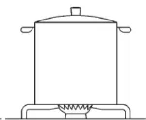
natural_image
Line drawing of a cooking pot on a heating element (no text or symbols)FIG. 2

USO
Note:

USO
ATTENZIONE:
MISURE DA RISPETTARE (in mm)
| A B C | D | E | |||
| 2F (30) | 285 | 485 | 57.5 | 57.5 | 100 min. |
| 4F (60) | 553 | 473 | 67.5 | 59.5 | 175 min. |
| 5F (70) | 553 | 473 | 67.5 | 59.5 | 175 min. |
| 5F (90) | 833 | 475 | 62.5 | 62.5 | 73.5 min. |
| Fig. 7 | FIG. 8 FIG. 9 | FIG. 10 |


REGOLAZIONI
IT
FIG. 13
TRASFORMAZIONI
Σ Qn Gas Naturale = 4 kW
Σ Qn GPL = 291 g/h
TENSIONE = 220 - 240 V\~
FREQUENZA = 50/60 Hz
4 FUOCHI (60)
CATEGORIA = I_2H3+
Σ Qn Gas Naturale = 6.95 kW
Σ Qn GPL = 505 g/h
TENSIONE = 220 - 240 V\~
FREQUENZA = 50/60 Hz
5 FUOCHI (70)
CATEGORIA = II _2H3+
Σ Qn Gas Naturale = 10.40 kV
Σ Qn GPL = 756 g/h
TENSIONE = 220 - 240 V\~
FREQUENZA = 50/60 Hz
IT
DATI TECNICI DELLA REGOLAZIONE GAS DELL'APPARECCHIO
This appliance must be installed in compliance with the current provisions in force and only used in rooms equipped with adequate ventilation. Consult the instruction manual before proceeding with installation or use of the appliance. For another type of gas, operate as described in the directions for the installation and use.This household appliance is adjusted to work at:  | Ouesto apparecchio puñ essere installato e funzionare solo in locali permanentemente ventilati secondo le norme UNI 7129e 7131.Per collegare alla rete d distribuzione del gas usare tubi metalici rigidi o tubi metallid flessibili conformi alla norma UNI EN 14800.Consultare il libretto d'istruzioni prima d'installare questo apparecchio.Questo apparecchio è regolato per funzionare a:  | Acest aparat poate fi instalat si functiona doar in locuri permanent ventilate , asa cum prevad normele in vigoare. Pentru a conecta aparatul la reteaua de gaz, trebuie sa folositi tuburi metalice rigide sau tuburi metalice flexible, in conformitate cu dispozitiile normativului in vigoare.Acest aparat este reglat sa functioneze pentru:  |
Spotřebič musi být instalován pouze autorizovaným pracovníkem. Tento spotřebič musi být instalován v souladu s platnými předpisy a jeho použitíse připoušti pouze v dobre vétraném prostoru. Před instalováním a použiváním spotřebiče se seznamte s návodem.Tento spotřebič je nastaven na propan-butan avstu pni přetlak:  | Spotrebič musi byT iinstalovány iba autorizovaným pracovníkom. Tento spotrebič musi byT iinstalovaný v súlade s platnými predpsmi a može byT použitý iba v dobre vetranom priestore. Pred iinstaláciou a použivaním spotrebiča si pozome prečítajte návod.Tento spotrebič je nastavený na zemný plyn h a vstupný pretlak:  | Bu cihaz yürürlükteki yönelmeliklere uygun olarak ve sadece iyi havalandirlmış yerlerde tahss edilmelidir. Bu cihazı kumadan veya kullanmadan önce talimatları okuyunuz.Farkli tipte gazlar için, kullanma kilavuzunda belirtilen açıklamalara başvurunuz.Bu cihaz aşağıdatipi belirtilen gaz ile çalışmasiçin ayarlanmıştır:  |
| G20 -"p" 20 mbar 2H COD 003962760-0408 | ||
ASSISTENZA TECNICA E RICAMBI
Instructions for the installation and advice for the maintenance
G34AX1-236650 - G64AX1-236625
G640AX1-236636 - G760AX1-236651
G960AX1-234640
Instructions Manual
G34AX1-236650 - G64AX1-236625
G640AX1-236636 - G760AX1-236651
G960AX1-234640
natural_image
Exterior view of a stainless steel gas stove with four fuses (no text or symbols visible)gorenje
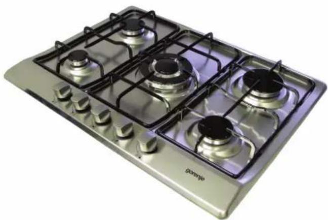
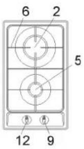
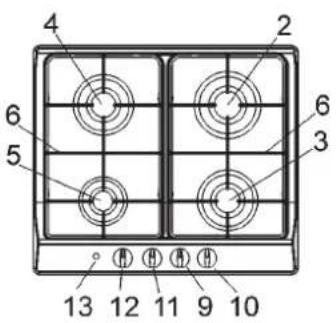
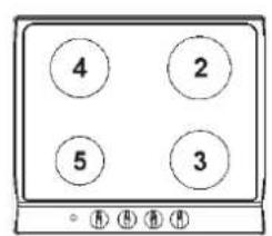
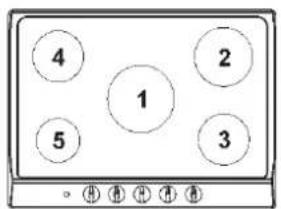
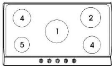
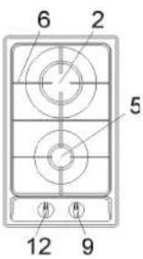
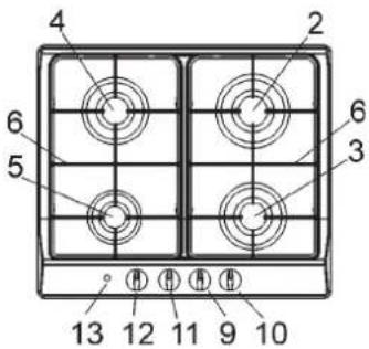
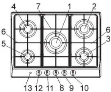
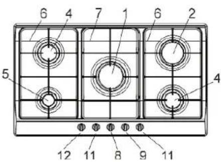
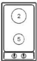
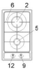
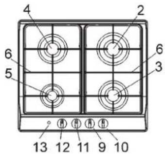
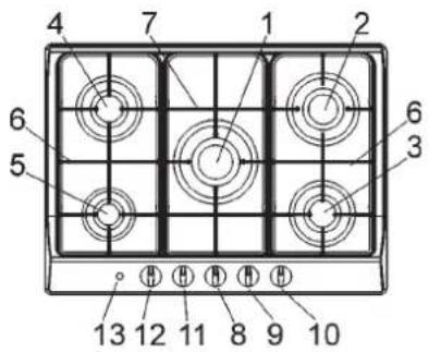
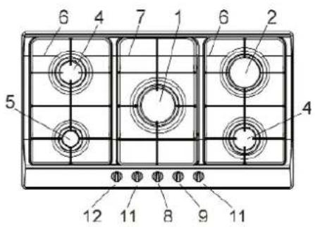
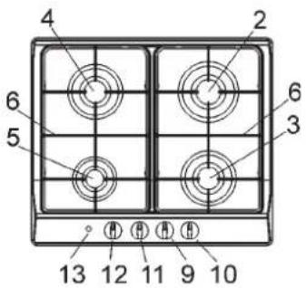
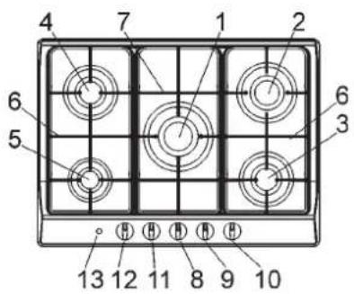
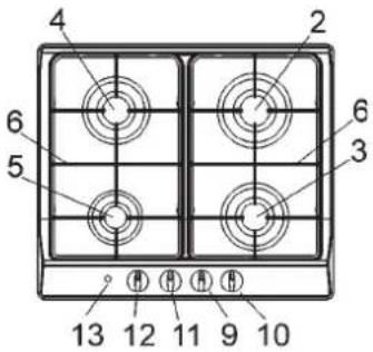
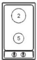
DESCRIPTION OF THE HOT PLATES
| TYPE: G34AX1-236650 | TYPES: MOD.: G64AX1-236625 - G640AX1-236636 |
 |  |
| TYPE: G760AX1-236651 | TYPE: G960AX1-234640 |
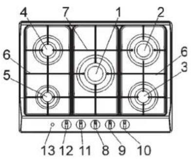 | 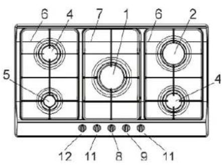 |
1 Ultra rapid gas burner of 3100 W
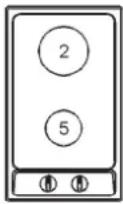
2 Rapid gas burner of 2800 W
3 Semirapid gas burner right front of 1400 W
4 Semirapid gas burner left back of 1750 W
5 Auxiliary gas burner of 1000 W
6 Enamelled steel pan support 2F
7 Central enamelled steel pan support
8 Burner n° 1 control knob
9 Burner n° 2 control knob
10 Burner n° 3 control knob
11 Burner n° 4 control knob
12 Burner n° 5 control knob
13 Electric ignition button
Attention: this appliance has been manufactured for domestic use only and it employment by private person.
USE
1) BURNERS
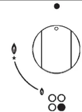
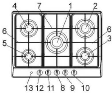
A diagram is screen-printed above each knob on the front panel. This diagram indicates to which burner the knob in question corresponds. After having opened the gas mains or gas bottle tap, light the burners as described below:
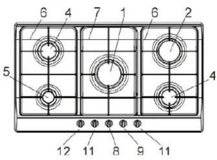
- Manual ignition
Push and turn the knob corresponding to the required burner in an anticlockwise direction until it reaches the full on position (large flame fig. 1), then place a lighted match near the burner.
- Electrical ignition
Push and turn the knob corresponding to the required burner in an anticlockwise direction until it reaches the full on position (large flame fig. 1), then depress and release the ignition button "E".
- Automatic electrical ignition
Push and turn the knob corresponding to the required burner in an anticlockwise direction until it reaches the full on position (large flame fig. 1), then depress the knob.
- Lighting burners equipped with flame failure device
The knobs of burners equipped with flame failure device must be turned in an anticlockwise direction until they reach the full on position (large flame fig. 1) and come to a stop. Now depress the knob in question and repeat the previously indicated operations.
Keep the knob depressed for about 10 seconds once the burner has ignited.
HOW TO USE THE BURNERS
Bear in mind the following indications in order to achieve maximum efficiency with the least possible gas consumption:
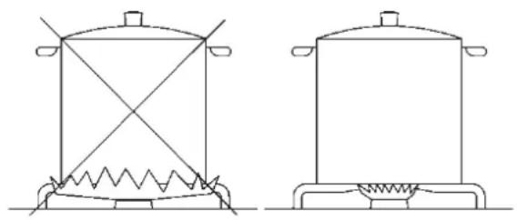
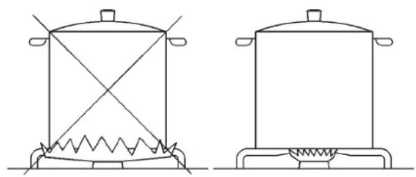
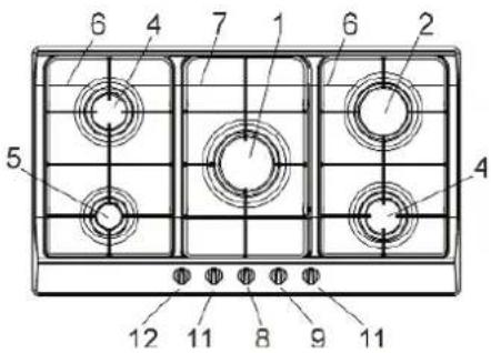
- Use adequate pans for each burner (consult the following table and fig. 2).
- When the pan comes to the boil, set the knob to the reduced rate position (small flame fig. 1).
- Always place a lid on the pans.
- Use only pan with a flat bottom.
Burners Power ratings Pan ∅ in cm
Ultra rapid 3100 24 ÷ 26
Rapid 2800 20 ÷ 22
Semirapid right front 1400 16 ÷ 18
Semirapid left back 1750 16 ÷ 18
Auxiliary 1000 10 ÷ 14
WARNINGS:
- burners with flame failure device may only be ignited when the relative knob has been set to the Full on position (large flame fig. 1).
- Matches can be used to ignite the burners in a blackout.
- Never leave the appliance unattended when the burners are being used. Make sure there are no children in the near vicinity. Particularly make sure that the pan handles are correctly positioned and keep a chek on foods requiring oil and grease to cook since these products can easily catch fire.
- The machine must not be used by people (including children) with impaired mental or physical capacities, or without experience of using electrical devices, unless supervised or instructed by an expert adult responsible for their care and safety. Children should not be allowed to play with the equipment.
- Never use aerosols near the appliance when it is operating.
- If the built-in hot plate has a lid, any spilt food should be immediately removed from this before it is opened. If the appliance has a glass lid, this could shatter when the hot plate becomes hot. Always switch off all the burners before closing the lid.
- Containers wider than the unit are recommended.
natural_image
Simple line drawing of a circle with a star and four small circles below, no text or symbols present.FIG. 1
natural_image
Line drawings of two identical cooking pots with heating elements and a spring (no text or symbols)FIG. 2

USE
Notes:
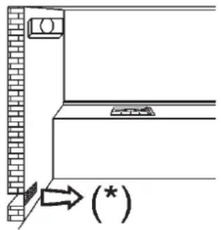
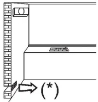
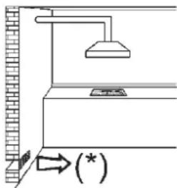
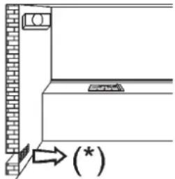
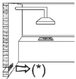
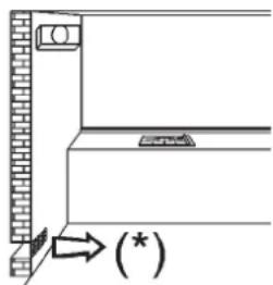
Use of a gas cooking appliance produces heat and moisture in the room in which it is installed.
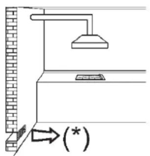
The room must therefore be well ventilated by keeping the natural air vents clear (fig. 3) and by activating the mechanical aeration device (suction hood or electric fan fig. 4 and fig. 5).
Intensive and lengthy use of the appliance may require additional ventilation. This can be achieved by opening a window or by increasing the power of the mechanical exhausting system if installed.
(*) AIR INLET: SEE INSTALLATION CHAPTER (PARAGRAPHS 5 AND 6)
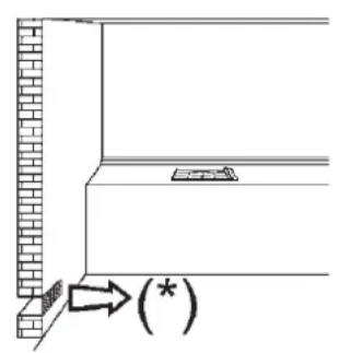
FIG. 3 FIG. 4 FIG. 5

CLEANING
IMPORTANT:
Always disconnect the appliance from the gas and electricity mains before carrying out any cleaning operation.
2) HOT PLATE
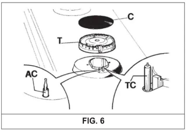
Periodically wash the hot plate, the enamelled stell pan support, the enamelled burner caps "C" and the burner heads "T" (see fig. 6) with lukewarm soapy water. Following this, all parts should be thoroughly rinsed and dried. Never wash them while they are still warm and never use abrasive powders. Do not allow vinegar, coffee, milk, salted water, lemon or tomato juice from remaining in contact with the enamelled surfaces for long periods of time.
WARNINGS:
Comply with the following instructions, before remounting the parts:
- Check that burner head slots "T" (fig. 6) have not become clogged by foreign bodies.
- Check that enamelled burner cap "C"(fig. 6) have correctly positioned on the burner head. It must be steady.
- The exact position of the pan support is established by the rounded corners, which should be set towards the side edge of the hot plate.
- Do not force the taps if they are difficult open or close. Contact the technical assistance service for repairs.
- Don't use steam jets for the equipment cleaning.
INSTALLATION
TECHNICAL INFORMATION FOR THE INSTALLER
Installation, adjustments of controls and maintenance must only be carried out by a qualified engineer.
Incorrect installation may cause damage to persons, animals or property for which the Manufacturer shall not be considered responsible.
During the life of the system, the automatic safety or regulating devices on the appliance may only be modified by the manufacturer or by his duly authorized dealer.
3) INSTALLING THE HOT PLATE
Check that the appliance is in a good condition after having removed the outer packaging and internal wrappings from around the various loose parts. In case of doubt, do not use the appliance and contact qualified personnel.
Never leave the packaging materials (cardboard, bags, polystyrene foam, nails, etc.) within children's reach since they could become potential sources of danger.
The measurements of the opening made in the top of the modular cabinet and into which the hot plate will be installed are indicated in either fig. 7. Always comply with the measurements given for the hole into which the appliance will be recessed (see fig. 7 and 8).
The appliance belongs to class 3 and is therefore subject to all the provisions established by the provisions governing such appliances.
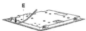
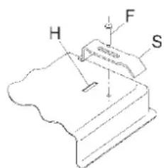
4) FIXING THE HOT PLATE
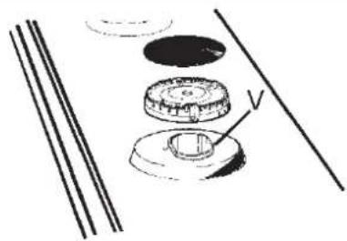
The hot plate has a special seal which prevents liquid from getting into the cabinet. Strictly comply with the following instructions in order to correctly apply this seal:
- Detach the seals from their backing, checking that the transparent protection still adheres to the seal itself.
- Overturn the hot plate and correctly position seal "E" (fig. 9) under the edge of the hot plate itself, so that the outer side of the seal perfectly matches the outer edge of the hot plate. The ends of the strips must fit together without overlapping.
- Evenly and securely fix the seal to the hot plate, pressing into place with the fingers and remove the strip of protective paper from the seal and set the plate into the hole made in the cabinet.
- Fix the hob with the proper brackets "S" and fit the prominent part into the porthole "H" on the bottom; turn the screw "F" until the bracket "S" stick on the top (fig. 10).
- In order to avoid accidental touch with the overheating bottom of the hob, during the working, is necessary to put a wooden insert, fixed by screws, at a minimum distance of 50 mm from the top (see fig. 7).
COMPLY WITH THE DIMENSIONS (mm)
| A B | C D | E | |||
| 2F (30) | 285 | 485 | 57.5 | 57.5 | 100 min. |
| 4F (60) | 553 | 473 | 67.5 | 59.5 | 175 min. |
| 5F (70) | 553 | 473 | 67.5 | 59.5 | 175 min. |
| 5F (90) | 833 | 475 | 62.5 | 62.5 | 73.5 min. |
| 760 Min. 50 mm | |||
| FIG. 7 FIG. 8 FIG. 9 | FIG. 10 | ||

INSTALLATION
IMPORTANT INSTALLATION SPECIFICATIONS
The installer should note that the appliance that side walls should be no higher than the hot plate itself. Furthermore, the rear wall, the surfaces surrounding and adjacent to the appliance must be able to withstand an overtemperature of 65K.
The adhesive used to stick the plastic laminate to the cabinet must be able to withstand a temperature of not less than 150^ C otherwise the laminate could come unstuck.
The appliance must be installed in compliance with the provisions in force.
This appliance is not connected to a device able to dispose of the combustion fumes. It must therefore be connected in compliance with the above mentioned installation standards. Particular care should be paid to the following provisions governing ventilation and aeration.
5) ROOM VENTILATION
It is essential to ensure that the room in which the appliance is installed is permanently ventilated in order to allow the appliance itself to operate correctly. the necessary amount of air is that required for regular gas combustion and ventilation of the relative room, the volume of which must not be less than 20 m ^-3 . Air must naturally flow through permanent openings in the walls of the room in question. These openings must vent the fumes outdoors and their section must be at least 100 cm ^2 (see fig. 3). Construction of the openings must ensure that the openings themselves may never be blocked. Indirect ventilation by air drawn from an adjacent room is also permitted, in strict compliance with the provisions in force.
CAUTION: if the burners of the cooking top are without safety thermocouple, the ventilation outlet must have a minimum 200 cm ^2 section.
6) LOCATION AND AERATION
Gas cooking appliances must always dispose of their combustion fumes through hoods. These must be connected to flues, chimneys or straight outside. If it is not possible to install a hood, an electric fan can be installed on a window or on a wall facing outside (see fig. 4). This must be activated at the same time as the appliance (see fig. 5), so long as the specifications in the provisions in force are strictly complied with.
7) GAS CONNECTION
Before connecting the appliance, check that the values on the data label affixed to the underside of the hot plate correspond to those of the gas and electricity mains in the home.
A label on the appliance indicates the regulating
conditions: type of gas and working pressure. Gas connection must comply with the pertinent standards and provisions in force.
When gas is supplied through ducts, the appliance must be connected to the gas supply system:
o with a rigid steel pipe. The joints of this pipe must consist of threaded fittings conforming to the standards.
o With copper pipe. The joints of this pipe must consist of unions with mechanical seals.
o With seamless flexible stainless steel pipe. The length of this pipe must be 2 meters at most and the seals must comply with the standards.
When the gas is supplied by a bottle, the appliance must be fuelled by a pressure governor conforming to the provisions in force and must be connected:
o with a copper pipe. The joints of this pipe must consist of unions with mechanical seals.
o With seamless flexible stainless steel pipe. The length of this pipe must be 2 meters at most and the seals must comply with the standards. It is advisable to apply the special adapter to the flexible pipe. This is easily available from the shops and facilitates connection with the hose nipple of the pressure governor on the bottle.
With rubber hose pipe in compliance with standards. The diameter of this hose pipe must be 8 mm and its length must be no less than 400 mm and no more than 1500 mm. It must be firmly fixed to the hose nipple by means of the safety clamp specified by standards.
At the connection end, verify the gasproof using a soap solution, never a flame.
WARNINGS:
Remember that the gas inlet union on the appliance is a 1/2" gas parallel male type in compliance with EN 10226 standards.
Installation of stainless steel pipe and rubber hose pipe must ensure that it is never able to touch mobile parts of the built-in cabinet (eg. drawers).
Furthermore, it must not pass through compartments that could be used for storage purposes.
When using a rubber hose pipe, it is essential to comply with the following instructions:
- no part of the pipe must be able to touch parts the temperature of which exceeds 65K.
- The pipe must not be pulled or twisted, throttled or tightly bent.
- It must not come into contact with sharp edges or corners.
- It must be easy to inspect the entire pipe length in order to check its state of wear.
- The pipe must be replaced within the date stamped on the pipe itself.
- The appliance complies with the provisions of the following EEC Directives:
90/396 + 93/68 regarding gas safety.
INSTALLATION
The electrical connections of the appliance must be carried out in compliance with the provisions and standards in force.
Before connecting the appliance, check that:
- The electrical capacity of the mains supply and current sockets suit the maximum power rating of the appliance (consult the data label applied to the underside of the hot plate).
- The socket or system has an efficient earth connection in compliance with the provisions and standards in force. The manufacturer declines all responsibility for failing to comply with these provisions.
When the appliance is connected to the electricity main by a socket:
- Fit a standard plug suited to the load indicated on the data label to the cable.
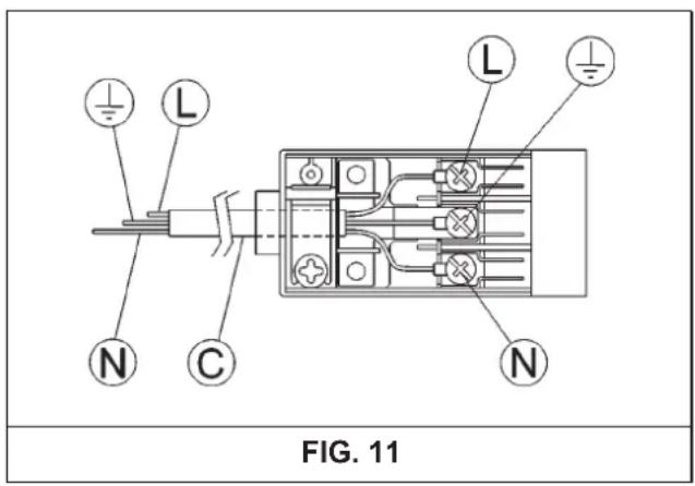
- Fit the wires following figure n.11, taking care of respecting the following correspondences:
letter L (live) = brown wire;
letter N (neutral) = blue wire;
earth symbol ≠ green - yellow wire
- The power supply cable must be positioned so that no part of it is able to reach an overtemperature of 65K.
- Never use reductions, adapters of shunts for connection since these could create false contacts and lead to dangerous overheating.
- The outlet must be accessible after the built-in.
When the appliance is connected straight to the electricity main:
- Install an omnipolar circuit-breaker between the appliance and the electricity main. This circuit-breaker should be sized according to the load rating of the appliance and possess a minimum 3 mm gap between its contacts.
- Remember that the earth wire must not be interrupted by the circuit-breaker.
- Alternatively, the electrical connection may also be protected by a high sensitivity differential circuit-breaker.
You are strongly advised to fix the relative yellow-green earth wire to an efficient earthing system.
WARNINGS:
All our appliances are designed and manufactured in compliance with European standards EN 60 335-1, EN 60 335-2-6 and EN 60 335-2-102 plus the relative amendments. The appliance complies with the provisions of the following EEC Directives:
- CEE 2004/108/CE regarding to electromagnetic compatibility.
- CEE 2006/95 regarding electrical safety.

ADJUSTMENTS
Always disconnect the appliance from the electricity main before making any adjustments. All seals must be replaced by the technician at the end of any adjustments or regulations. Our burners do not require primary air adjustment.
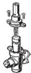
9) TAPS
"Reduced rate" adjustment
- Switch on the burner and turn the relative knob to the "Reduced rate" position (small flame fig.1).
- Remove knob (fig. 12) of the tap, which is simply pressed on to its rod.
- Insert a small screwdriver "D" into hole "C" (fig. 12) and turn the throttle screw to the right or left until the burner flame has been adequately regulated to the "Reduced rate" position.
Check that the flame does not go out when the knob is sharply switched from the "Full on" to the "Reduced rate" position.
It is understood that only burners operating with G20 gas should be subjected to the above mentioned adjustments. The screw must be fully locked when the burners operate with G30 or G31 gas (turn clockwise).
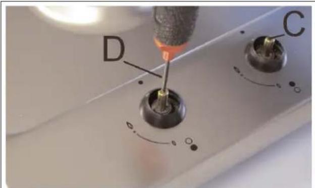
FIG. 12
CONVERSIONS
10) REPLACING THE INJECTORS
The burners can be adapted to different types of gas by mounting injectors suited to the type of gas in question. To do this, first remove the burner tops using a wrench "B". Now unscrew injector "A" (see fig. 13) and fit a injector corresponding to the utilized type of gas in its place. It is advisable to strongly tighten the injector in place.
After the injectors have been replaced, the burners must be regulated as explained in
paragraphs 9. The technician must reset any seals on the regulating or pre-regulating devices. The envelope with the injectors and the labels can be included in the kit, or at disposal to the authorized customer Service Centre.
For the sake of convenience, the nominal rate table also lists the heat inputs of the burners, the diameter of the injectors and the working pressures of the various types of gas.
BURNER ARRANGEMENT ON THE HOT PLATE
TABLE
| BURNERS | GAS | NORMAL PRESSURE mbar | NORMAL RATE | INJECTOR DIAMETER 1/100 mm | NOMINAL HEAT INPUT (W) | |||
| N° | DESCRIPTION | g/h | l/h | Min. | Max. | |||
| 1 | ULTRA RAPID | G 30 - BUTANE 28 - G 31 - PROPANE 37 G 20 - NATURAL 20 | 30 225 90 1400 222 90 1400 295 | 3100 3100 295 | 121 | Y 1400 3100 | ||
| 2 | RAPID | G 30 - BUTANE G 31 - PROPANE G 20 - NATURAL | 28 - 30 20 4 83 37 200 83 20 | 800 2800 800 267 | 117 S | 800 | 2800 | |
| 3 | SEMIRAPID RIGHT FRONT | G 30 - BUTANE G 31 - PROPANE G 20 - NATURAL | 28 - 30 102 58 37 100 58 20 | 500 1400 500 133 | 85 Y | 500 | 1400 | |
| 4 | SEMIRAPID LEFT BACK | G 30 - BUTANE 28 - G 31 - PROPANE G 20 - NATURAL | 30 127 65 37 20 | 500 125 | 167 | 65 97 Z | 500 500 | 1750 1750 |
| 5 | AUXILIARY | G 30 - BUTANE G 31 - PROPANE G 20 - NATURAL | 28 - 30 37 20 | 73 71 | 95 | 50 50 72 X | 400 400 400 | 1000 1000 1000 |
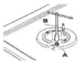
FIG. 13
CONVERSIONS
BURNER ARRANGEMENT ON THE HOT PLATE
TABLE
| BURNERS | GAS | NORMAL PRESSURE mbar g/h l/h 1/100 mm | INJECTOR DIAMETER Min. Max. | NOMINAL HEAT INPUT (W) | |||||
| N° | DESCRIPTION | ||||||||
| 2 | RAPID | G 30 - BUTANE 28 G 31 - PROPANE 37 G 20 - NATURAL 20 | 30 218 85 750 3000 200 85 750 3000 267 115 Y 750 3000 | ||||||
| 5 | AUXILIARY | G 30 - BUTANE G 31 - PROPANE G 20 - NATURAL | 28 - 30 37 20 | 73 71 | 50 50 72 X | 400 400 400 | 1000 1000 1000 | ||
SERVICING
Always disconnect the appliance from the electricity and gas mains before proceeding with any servicing operation.
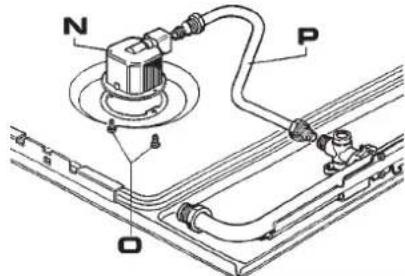
11) REPLACING HOT PLATE PARTS
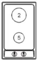
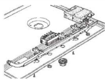
When parts housed within the hot plate need replacing, it is first necessary to remove the hot plate itself from the cabinet, to overturn it, unscrew screws "V" and to remove part (see fig. 14).
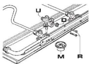
After having carried out the above listed operations, the burners (fig. 15), taps (fig. 16) and electrical components can all be replaced (fig. 17).
It is advisable to change seal "D" whenever a tap is replaced to ensure a perfect tightness.
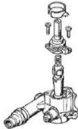
Greasing the taps (see fig. 18 - 19)
If a tap becomes stiff to operate, it must be immediately greased in compliance with the following instructions:
- Remove the tap.
- Clean the cone and its housing using a cloth soaked in diluent.
- Lightly spread the cone with the relative grease.
- Fit the cone back in place, operate it several times and then remove it again. Eliminate any excess grease and check that the gas ducts have not become clogged.
- Fit all parts back in place, complying with the demounting order in reverse.
- The tight closure test must be done using a foamy liquid.
To facilitate the servicing technician's task, here is a chart with the types and sections of the powering cables and the ratings of the electrical components.
 |  |  |
| FIG. 14 FIG. 15 FIG. 16 | ||
 |  |  |
| FIG. 17 FIG. 18 FIG. 19 | ||

SERVICING
CABLE TYPES AND SECTIONS
| TYPE OF TYPE OF SINGLE - PHASE HOT PLATE CABLE POWER SUPPLY | |
| Gas hot plate H05 RR - F Section 3 x 0.75 mm | 2 |
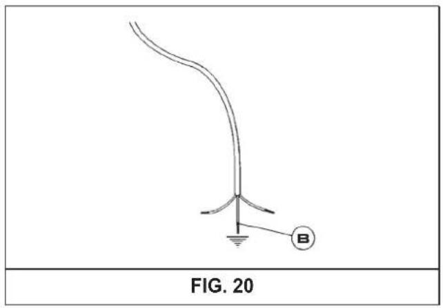
ATTENTION!!!
If the power supply cable is replaced, the installer should leave the ground wire longer than the phase conductors (fig. 20) and comply with the recommendations given in paragraph 8.
natural_image
Diagram of a curved structure with labeled point B and scale marker, no readable text or symbols beyond labelsTECHNICAL DATA ON THE DATA LABEL
2 BURNERS (30)
CATEGORY: I_2H3+
BUTANE = 28 - 30 mbar
PROPANE = 37 mbar
NATURAL = 20 mbar
Σ Qn Gas Natural = 4 kW
Σ Qn LPG = 291 g/h
VOLTAGE = 220 - 240 V \~
FREQUENCY = 50/60 Hz
4 BURNERS (60)
CATEGORY: II_2H3+
BUTANE = 28 - 30 mbar
PROPANE = 37 mbar
NATURAL = 20 mbar
Σ Qn Gas Natural = 6.95 kW
Σ Qn LPG = 505 g/h
VOLTAGE = 220 - 240 V \~
FREQUENCY = 50/60 Hz
5 BURNERS (70)
CATEGORY: I_2H3+
BUTANE = 28 - 30 mbar
PROPANE = 37 mbar
NATURAL = 20 mbar
Σ Qn Gas Natural = 10.05 kW
Σ Qn LPG = 731 g/h
VOLTAGE = 220 - 240 V \~
FREQUENCY = 50/60 Hz
5 BURNERS (90)
CATEGORY: II_2H3+
BUTANE = 28 - 30 mbar
PROPANE = 37 mbar
NATURAL = 20 mbar
Σ Qn Gas Natural = 10.40 kW
Σ Qn LPG = 756 g/h
VOLTAGE = 220 - 240 V \~
FREQUENCY = 50/60 Hz
TECHNICAL DATA FOR THE APPLIANCE GAS REGULATION
This appliance must be installed in compliance with the current provisions in force and only used in rooms equipped with adequate ventilation. Consult the instruction manual before proceeding with installation or use of the appliance.For another type of gas, operate as described in the directions for the installation and use.This household appliance is adjusted to work at:  | Questo apparecchio puñ essere installato e funzionare solo in locali permanentemente ventilati secondo le norme UNI 7129e 7131.Per collegare alla rete d distribuzione del gas usare tubi metallici rigidi o tubi metallici flessibili conformi alla norma UNI EN14800.Consultare il libretto d'istruzioni prima d'installare questo apparecchio.Questo apparecchio è regolato per funzionare a:  | Acest aparat poate fi instalat si functiona doar in locuri permanent ventilate , asa cum prevad normele în vigoare.Pentru a conecta aparatul la reteaua de gaz, trebuie sa folositi tuburi metalice rigide sau tuburi metalice flexible, in conformitate cu dispozitiile normativului în vigoare.Acest aparat este reglat sa functioneze pentru:  |
Spotřebič musi být instalován pouze autorizovaným pracovníkem. Tento spotřebič musi být instalován v souladu s platnými předpisy a jeho použitise připoušti pouze v dobře vétraném prostoru. Před instalováním a použiváním spotřebiče se seznamte s návodem.Tento spotřebič je nastaven na propan-butan a vstu pní přetlak:  | Spotrebič musi byT inštalovány iba autorizovaným pracovníkom. Tento spotrebič musi byT inštalovaný v súlade s platnými predpismi a može byT použitý iba v dobre vetranom priestore. Pred inštaláciou a použivanim spotrebiča si pozome prečítajte návod.Tento spotrebič je nastavený na zemný plyn h a vstupný pretlak:  | Bu cihaz yürürlükteki yönetmeliklere uygun olarak ve sadece iyi havalandirilmis yerlerde tahss edilmelidir. Bu cihazı kumadan veya kullanmadan önce talimatları okuyunuz.Farklı tipte gazdar için, kullanma kilavuzunda belirtilen açıklamalara besvurunuz.Bu cihaz asagidatipi belirtilen gaz ile çalışmasi için ayarlanmıştır:  |
| G20 - "p" 20 mbar 2H COD DIEDB67GO - 0400 | ||
TECHNICAL ASSISTANCE AND SPARE PARTS
Before leaving the factory, this appliance will have been tested and regulated by expert and specialized personnel in order to guarantee the best performances.
Any repairs or adjustments which may be subsequently required may only be carried out by qualified personnel with the utmost care and attention.
For this reason, always contact your Dealer or our nearest After Sales Service Center whenever repairs or adjustments are required, specifying the type of fault and the model of the appliance in your possession.
Please also note that genuine spare parts are only available from our After Sales Service Centers and authorized retail outlets.
The above data are printed on the data label put on the inferior part of the appliance and on the packing label.
The above informations give to the technical assistant the possibility to get fit spare parts and a heaven-sent intervention. We suggest to fill the table below.
MARK:
MODEL:
SERIES:
This appliance is marked according to the European directive 2002/96/EC on Waste Electrical and Electronic Equipment (WEEE).
This guideline is the frame of a European-wide validity of return and recycling on Waste Electrical and Electronic Equipment.

natural_image
Exterior view of a stainless steel gas stove with four panes (no text or symbols visible)gorenje
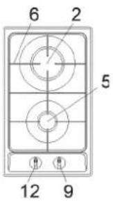
POPIS VARNÝCH DOSIEK
| TYPY: G34AX1-236650 | TYPY: G64AX1-236625 - G640AX1-236636 |
 |  |
| TYPY: G760AX1-236651 | TYP.: G960AX1-234640 |
 |  |
1 Horák veľmi rýchly 3100 W
2 Horák rýchly 2800 W
3 Horák polorýchly snížené 1400 W
4 Horák polochýchly 1750 W
5 Horák doplnkový 1000 W
6 Rošt zo smaltovej ocele pre dva horáky
7 Centrálny rošt zo smaltovanej ocele
8 Ovládač k horáku č. 1
9 Ovládač k horáku č. 2
10 Ovládač k horáku č. 3
11 Ovládač k horáku č. 4
12 Ovládač k horáku č. 5
13 Tlačidlo elektrického zapal'ovania
OBR. 3
OBR. 4
OBR. 5

ČISTENIE
POZOR:
POKYNY DOLEŽITÉ PRE INSTALÁCIU
SK
NASTAVENIA

OBR. 13
VÝMENY
USPORIADANIE HORÁKOV
TABUL'KA
| HORÁKY | PLYN | PRETLAK | TEPLOTNÝ PRIETOK | PRIEMER TRYSKY | TEPLOTNÝ PRIETOK W | |||
| č | TYP | mbar | g/h | l/h | 1/100 mm | min. | max. | |
| 2 | RÝCHLY | G 30 - BUTÁNG 31 - PROPÁNG 20 - ZEMNÝ | 303020 | 218200 | 267 | 8585115 Y | 750750750 | 300030003000 |
| 5 | DOPLNKOVÝ | G 30 - BUTÁNG 31 - PROPÁNG 20 - ZEMNÝ | 303020 | 7371 | 95 | 505072 X | 400400400 | 100010001000 |
ÚDRŽBA
natural_image
Exterior view of a stainless steel gas stove with four fuses and control knobs (no text or symbols visible)gorenje
POPIS VARNÉ DESKY
| TYP: G34AX1-236650 | TYP: G64AX1-236625 - G640AX1-236636 |
 |  |
| TYP: G760AX1-236651 | TYP: G960AX1-234640 |
 |  |
OBR. 3
OBR. 4
OBR. 5

ČIŠTĚNÍ
Upozornění:
natural_image
Isometric line drawing of a kitchen cabinet with drawers and a grid-patterned counter (no text or symbols)OBR. 8
OBR. 9
OBR. 10

INSTALACE
DÜLEŽITÉ PŘEDPISY PRO INSTALACI

SEŘÍZENÍ

OBR. 13
PŘEMĚNA NA JINÝ DRUH PLYNU
USPORIADANIE HORÁKOV
TABUL'KA
natural_image
Exterior view of a stainless steel gas stove with four fuses and control knobs (no text or symbols visible)gorenje
OCAKLARIN TANIMLAMASI
| TÝPLER: G34AX1-236650 | TÝPLER: G64AX1-236625 - G640AX1-236636 |
 |  |
| TÝPLER: G760AX1-236651 | TÝPLER: G960AX1-234640 |
 |  |
natural_image
Simple line drawing of a circle with a star and four circles below, no text or symbols present.ŞEKİL 1
natural_image
Line drawings of two identical cooking pots with heating elements, no text or symbols presentŞEKİL 2

KULLANIM
Notlar:

ŞEKİL 13
ÇEVÝRMELER
$$ G 3 0 - B \ddot {U} T A N = 3 0 m b a r $$
$$ G 3 1 - P R O P A N = 3 0 \mathrm{mbar} $$
$$ G 2 0 - D O G A L G A Z = 2 0 \mathrm{mbar} $$
$$ G 3 0 - B \ddot {U} T A N = 3 0 m b a r $$
$$ G 3 1 - P R O P A N = 3 0 \text {mbar} $$
$$ G 2 0 - D O G A L G A Z = 2 0 \mathrm{mbar} $$
natural_image
Exterior view of a stainless steel gas stove with four fumes and black grilles (no text or symbols visible)gorenje
DESCRIEREA PLITELOR DE GATIT
| TIP: G34AX1-236650 | TIP: G64AX1-236625 - G640AX1-236636 |
 |  |
| TIP: G760AX1-236651 | TIP: G960AX1-234640 |
 |  |
- Arzator cu tripla coroana de 3100 W
- Arzator rapid de 2800 W
- Arzator semirapid redus dreapta fata de 1400 W
- Arzator semirapid stanga spate de 1750 W
- Arzator auxiliar de 1000 W
- Grila de otel smaltuit 2 ochiuri
- Grila de otel centrala
- Buton comanda arzator nr. 1
- Buton comanda arzator nr. 2
- Buton comanda arzator nr. 3
- Buton comanda arzator nr. 4
- Buton comanda arzator nr. 5
- Buton aprindere electric
natural_image
Simple line drawing of a circle with a star and four small circles below, no text or symbols present.FIG. 1
| Arzatoare Putere W | ∅ Vas cm | |
| Tripla coroana 3100 | 24 ÷ 26 | |
| Rapid 2800 | 20 ÷ 22 | |
| Semirapid redus fata dr. | 1400 | 16 ÷ 18 |
| Semirapid spate stg. | 1750 | 16 ÷ 18 |
| Auxiliar | 1000 | 10 ÷ 14 |
AVERTISMENT:
natural_image
Simple line drawing of a cooking pot with a wavy base and two handles (no text or symbols)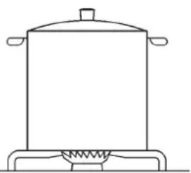
natural_image
Line drawing of a cooking pot on a stove (no text or symbols)FIG. 2

UTILIZARE
NOTA:
utilizarea unui aparat de gatit cu gaz produce caldura si umiditate in camera in care este instalat. Este deci necesar sa asigurati o buna aerisire lasand liberegurile de ventilatie naturala (fig. 3) si activand dispozitivul mecanic de aerisire (hota de aspiratie sau ventilator, fig. 4 si 5).
FIG. 11
REGLAJE
Inainte de a executa orice reglaje deconectati aparatul de la curent.
La terminarea reglajelor, eventualele sigilii trebuie refacute de tehnician.
FIG. 13
MODIFICARI
DISPUNEREA ARZĂTOARELOR
TABEL
| ARZATOARE | GAZ | PRESIUNE DE LUCRU mbar g/h l/h | DEBIT TERMIC | DIAMETRU DUZA MIN. MAX. | DEBIT TERMIC (W) | |||
| N° | DENUMIRE | 1/100 mm | ||||||
| 2 | RAPID | G30 - BUTAN 28 - G31 - PROPAN 37 G20 - NATURAL 20 | 30 218 85 750 200 85 750 3000 267 115 Y 7 | 3000 | ||||
| 5 | AUXILIARY | G30 - BUTAN G31 - PROPAN G20 - NATURAL 20 | 28 - 30 37 | 73 | 50 | 400 | 1000 | |
| 71 | 50 | 400 | 1000 | |||||
| 95 72 X 400 | 1000 | |||||||
INTRETINERE
Inainte de efectuarea oricarei operatii de intretinere, deconectati aparatul de la reteaua de gaz si electrica.
$$ G 2 0 - G A Z N A T U R A L = 2 0 m b a r $$
$$ \Sigma \text { Qn Gas Naturale } = 6. 9 5 \mathrm{kW} $$
$$ \Sigma \mathrm{QnGPL} = 5 0 5 \mathrm{g/h} $$
$$ \text { Tensiune } = 2 2 0 - 2 4 0 \mathrm{V} \sim $$
$$ \text { Frecvență } = 5 0 / 6 0 \mathrm{Hz} $$
5 ARZĂTOARE (70)
$$ \text { C A T E G O R I A } = \mathrm{I} _ {2 \mathrm{H} 3 +} $$
$$ G 3 0 - B U T A N = 2 8 - 3 0 \mathrm{mbar} $$
$$ G 3 1 - P R O P A N = 3 7 \text {mbar} $$
$$ G 2 0 - G A Z N A T U R A L = 2 0 \mathrm{mbar} $$
$$ \Sigma \text { Qn Gas Naturale } = 1 0. 0 5 \mathrm{kV} $$
$$ \Sigma \mathrm{QnGPL} = 7 3 1 \mathrm{g/h} $$
$$ \text { Tensiune } = 2 2 0 - 2 4 0 \mathrm{V} \sim $$
$$ \text { Frecvență } = 5 0 / 6 0 \mathrm{Hz} $$
5 ARZĂTOARE (90)
$$ \text { C A T E G O R I A } = \mathrm{II} _ {2 \mathrm{H} 3 +} $$
$$ G 3 0 - B U T A N = 2 8 - 3 0 \mathrm{mbar} $$
$$ G 3 1 - P R O P A N = 3 7 \mathrm{mbar} $$
$$ G 2 0 - G A Z N A T U R A L = 2 0 m b a r $$
$$ \Sigma \text { Qn Gas Naturale } = 1 0. 4 0 \mathrm{kV} $$
$$ \Sigma \mathrm{QnGPL} = 7 5 6 \mathrm{g/h} $$
$$ \text { Tensiune } = 2 2 0 - 2 4 0 \mathrm{V} \sim $$
$$ \text { Frecvență } = 5 0 / 6 0 \mathrm{Hz} $$
DATE TEHNICE PRIVIND REGLAREA ALIMENTĂRII CU GAZ A APARATULUI
This appliance must be installed in compliance with the current provisions in force and only used in rooms, equipped with adequate ventilation. Consult the instruction manual before proceeding with installation or use of the appliance. For another type of gas, operate as described in the directions for the installation and use. This household appliance is adjusted to work at:
