80072 - Hydraulic jack VOREL - Free user manual and instructions
Find the device manual for free 80072 VOREL in PDF.


User questions about 80072 VOREL
0 question about this device. Answer the ones you know or ask your own.
Ask a new question about this device
Download the instructions for your Hydraulic jack in PDF format for free! Find your manual 80072 - VOREL and take your electronic device back in hand. On this page are published all the documents necessary for the use of your device. 80072 by VOREL.
USER MANUAL 80072 VOREL
PL PODNOŚNIK HYDRAULICZNY SŁUPKOWY
EN HYDRAULIC BOTTLE JACK
DE HYDRAULISCHER STEMPELWAGENHEBER
natural_image
White Vorel mechanical device with black handle and attached sensor, plus a white cylindrical tool (no visible text or symbols)80111 80120 80122
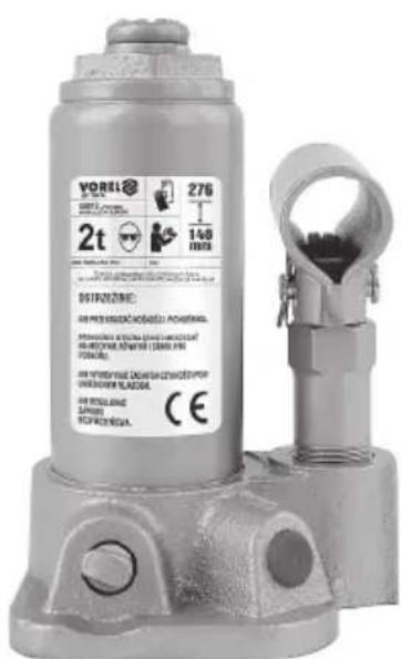
text_image
VOREL 276 140 mm 2t DISTROZENIE: AIR PIED WARDIC HABOZZI KONOMA. HABOZZI KONOMA (SANDER) 1400 (5000) AIR POWERING DABRIGAT/INCHSTOP UNLESSWATER PLAZA. AIR PIED LIME (200) BEVERIZONA. CE80012
80022
80032
80042
80052
80062
80072
80082
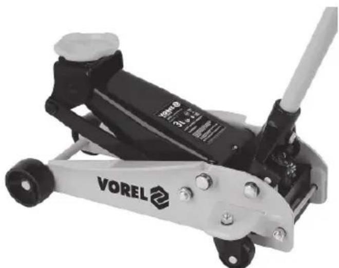
natural_image
Black and white Vorel 2 water pump tool with attached screw base (no visible text or symbols)80233
PL EN DE RU UA LT LV CZ SK HU RO ES FR IT NL GR BG PT HR AR
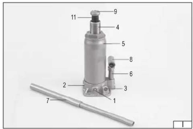
text_image
Labeled diagram of a mechanical device with numbered parts, including a cylindrical shaft and a vertical component.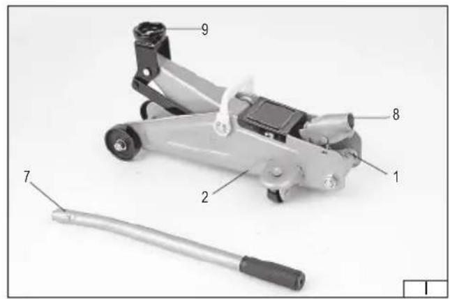
text_image
Labeled diagram of a mechanical device with numbered parts, including a tool and a handle.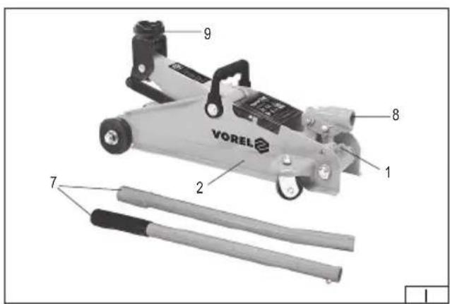
text_image
VOREL 1 2 8 9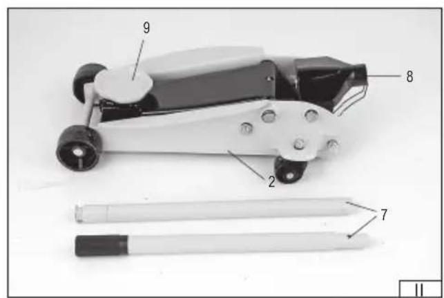
text_image
Labeled diagram of a mechanical device with numbered parts, including a pen and two writing tools.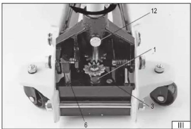
text_image
12 1 3 6 III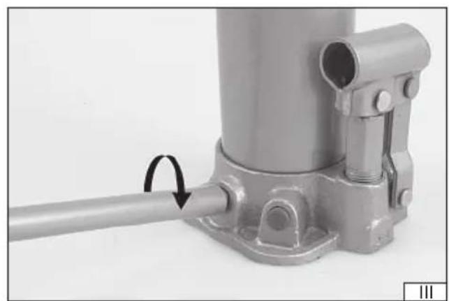
natural_image
Close-up of a metallic mechanical device with a cylindrical component and mounting base (no visible text or symbols)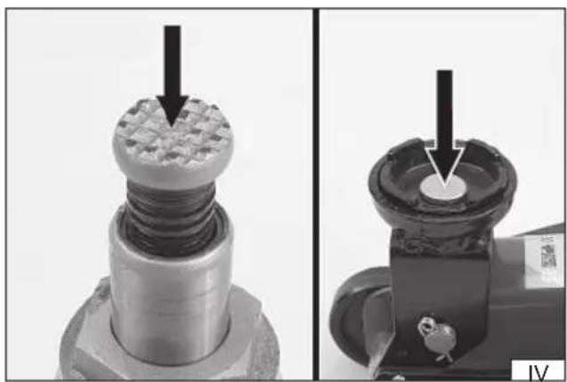
natural_image
Close-up of mechanical components with arrows indicating a machining process (no visible text or symbols)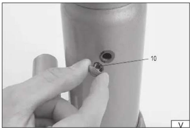
text_image
10 V- lever of the release valve
- support
- safety valve
- shaft of the lift
- oil tank
- oil pump
- arm of the lift
- socket of the arm
- saddle of the lift
- oil tank plug
- extension bolt
- protection handwheel
DE
Read the operating instruction
Wear protective goggles
The hydraulic lift has been designed to be used for tasks implying lifting significant weights. It must not be used as a permanent support element. It is also unacceptable to use the lift to transport lifted loads. The device has been designed exclusively for domestic use and must not be used professionally, namely in plants and for lucrative purposes. A correct, reliable and safe functioning of the device depends on its adequate operation, so:
Before you commence work with the tool, read the operating manual thoroughly and keep it for future reference.
The supplier shall not be held responsible for any damage and injuries caused due to using the tool for purposes it has not been designed for, failure to observe safety recommendations and the recommendations indicated within this manual. Using the device for tasks which do not comply with the purpose it has been designed for shall also cancel the guarantee rights the user is entitled to.
SAFETY RECOMMENDATIONS
The lift is a hydraulic device working under significant loads. During work it is required to observe basic safety principles.
Before you start work, read the operating manual and keep it for future reference.
Do not ever exceed the maximum load of the lift.
It is prohibited to use the device to lift people and animals.
The lift has been designed exclusively for the purpose of lifting, and must not be used for other purposes. It is required to use additional safety devices (e.g. racks) to support the lifted object, before work under it may commence.
In case of lifting vehicles it is necessary to block or wedge the wheels and engage the safety brake.
Do not leave a lifted load unattended. Do net permit children and those who have not been trained in operation of the device to enter the working area.
Do not wear loose clothes and jewellery. Gather long hair.
Use personal protection means.
The lift must be placed on an even, flat, hard and stable surface.
The lift must be placed upon the device to be lifted so that the load is supported in the middle section of the saddle.
It is absolutely prohibited to adjust the safety valve.
Keep the device far from sources of heat and flames, since they might damage the device or impair its functioning.
Before you proceed to lifting any load whatsoever, make sure that once the load has been lifted, the lift will not shift.
Before you proceed to lifting any load whatsoever, male sure the lift is not damaged in any way. If the lift requires repair, have it repaired by an authorised workshop.
Be prudent and do not work when you are tired or under influence of medicines.
Do not modify any elements of the lift, which may have impact on the compliance of the lift with the standard indicated in the declaration of compliance.
Have the device repaired exclusively in authorised service points, using solely original spare parts, so as to ensure the required level of safety during work.
The condition of the marking must be checked and that the marking remains as it was at the beginning.
The lifetime of the lift has been determined for 4 years from the date of its first use. After this period, the lift should be inspected at the manufacturer's authorized service center for further safety of use.
EN
ASSEMBLY AND OPERATION OF THE LIFT
The lift is delivered as an assembled system and does not require assembly or adjustments.
Before work it is required to realise approximately six full pumping cycles with the release valve open, so as to ensure appropriate distribution of the hydraulic oil.
It is required to check before each task all the screwed connections, and tighten them if necessary. This will increase safety of operation and prolong the life of the lift.
Lifting
Before lifting may commence, make sure that the operator of the lift has the lift itself and the lifted load within the range of sight during all realised movements.
Using the narrower end of the arm of the lift, close the release valve turning it home clockwise (III). Insert the lift arm into the socket.
For the 80111 jack, snap the two parts of the lifting arm together with the snap lock. With the narrow end of the lifting arm, close the release valve by turning it clockwise as far as it will go. Then insert the jack arm into the slot.
In case of the lift number 80233 both the sections of the lifting arm must be connected and protected with a screw. Then insert the arm of the lift into the socket and protect it with a handwheel so that it does not fall out. Close the release valve with the arm of the lift, turning it home clockwise (III).
Place the lift under the load to be lifted in the place designed for a lift (e.g. in case of vehicles), so that the load is supported in the central section of the saddle of the lift (IV).
If necessary in post lift sit is possible to unscrew the extension bolt until the saddle of the lift touches the lifted load.
Moving the arm upwards and downwards lift the load to the required height.
Once the load has been lifted, protect it from falling down using for example appropriate supports.
Lifting
Before lifting may commence, make sure that the operator of the lift has the lift itself and the lifted load within the range of sight during all realised movements.
Using the end of the arm of the lift, close the release valve turning it home clockwise. (II)
Place the lift under the load to be lifted in the place designed for a lift (e.g. in case of vehicles), so that the load is supported in the central section of the saddle of the lift. (III)
Insert the arm of the lift into the socket. Moving the arm upwards and downwards lift the load to the required height.
Once the load has been lifted, protect it from falling down using for example appropriate supports.
Lowering
Before lowering of the load may commence, make sure that the load to be lowered will not cause any injuries to the personnel.
Using the narrower end of the arm of the lift turn the release valve slowly anticlockwise. Do not open the release valve more than this is required to slowly lower the load.
Excessive opening of the valve may cause its removing from the casing.
Once the load has been completely lowered, disconnect the arm from the lift, and remove the lift from under the load. In case of post lifts, it is required to remove the extension bolt, if it was used.
Maintenance
If the lift is not used the shaft of the lift and the socket of the arm should be in the lower position. In case of post lifts also the extension bolt should be turned into the shaft of the lift. This will prevent the surface of the shaft from corrosion.
The lift must be kept clean, and the external moving elements of the lift must be lubricated at least every ten working hours.
Purging the hydraulic system
It is required to have the following maintenance action realised in a specialised service point.
From time to time the hydraulic system of the lift fills with air bubbles. This may impair the functional efficiency of the lift. If this is the case the hydraulic system of the lift must be purged.
Place the lift in such a manner that the shaft is in a vertical position. Open the release valve and remove the oil tank plug (V). Then move the pump of the lift energetically a couple of times so as to remove the air.
Close the release valve and replace the oil tank plug. Check the functioning of the lift, and if necessary repeat the purging procedure.
Filling the oil tank and lubrication
It is required to have the following maintenance action realised in a specialised service point.
Place the lift in such a manner that the shaft is in a vertical position. Move the pump and the shaft to the extreme lower position. Remove the oil tank plug (V).
EN
Use solely hydraulic oil whose viscosity class is SAE 10. It is prohibited to use other liquids for that purpose. Fill the tank to the lower edge of the oil inlet.
Purge the lift following the direction indicated in „Purging the hydraulic system".
Replace the oil tank plug. Check the functioning of the lift.
In regular intervals (at least every ten working hours) lubricate the articulated connections and other moving elements of the lift.
In case of post lifts, remember of periodical lubrication of the extension bolt thread.
Solution of problems
| The lift lowers under a load | The lift does not lift a load | The lift does not lift a load to the full height | The pump springs back during lifting | The lift does not lower completely | Oil is leaking from under the plug | |
| X | X | X | There may be insufficient quantity of oil in the lift. Fill the oil tank. | |||
| X | X | X | X | Air in the hydraulic system. Purge the hydraulic system. | ||
| X | There may be excessive quantity of oil in the lift. Remove the excess of oil | |||||
| X | X | The valves may not close completely. Lift the arm of the device a couple of times without any load and then lower it. | ||||
| X | A damaged back spring.Moving elements are not lubricated.Deformed arm driving elements. | |||||
| X | X | The release valve is not completely closed. Close the release valve. |
Replacement of the back spring in the powered lifts
It is required to have the following maintenance action realised in a specialised service point.
Lower the saddle of the lift, so that the back spring is as little stretched as possible. Using a tool remove the damaged spring from the holes and replace it with a new one. Check the functioning of the lift.
Handling worn jack components
Used oil and/or grease must be taken to a specialist waste disposal facility.
Used steel parts do not pose an environmental hazard and should be handed over to facilities that process ferrous metal waste.
DE
TECHNISCHE DATEN
| Index Tragkraft [T] Hubbereich [mm] Gewicht [kg] | ||
| 80012 2 140 - 260 2,2 | ||
| 80022 3 168 - 326 3,1 | ||
| 80032 5 185 - 355 3,9 | ||
| 80042 8 190 - 365 4,8 | ||
| 80052 10 195 - 375 5,6 | ||
| 80062 12 200 - 380 6,5 | ||
| 80072 15 205 - 390 7,6 | ||
| 80082 20 217 - 407 9,7 | ||
| 80111 2 135 - 340 9,0 | ||
| 80120 2 130 - 350 9,6 | ||
| 80122 2 130 - 350 9,7 | ||
| 80233 3 150 - 485 35,0 |
PRODUKTBESCHREIBUNG
PRODUKTA RAKSTUROJUMS
DECLARATION OF CONFORMITY
1025/80012/EC/2025
We declare and guarantee with full responsibility that the following products:
Hydraulic bottle jack 2 t; item no. 80012
Hydraulic bottle jack 3 t; item no. 80022
Hydraulic bottle jack 5 t; item no. 80032
Hydraulic bottle jack 8 t; item no. 80042
Hydraulic bottle jack 10 t; item no. 80052
Hydraulic bottle jack 12 t; item no. 80062
Hydraulic bottle jack 15 t; item no. 80072
Hydraulic bottle jack 20 t; item no. 80082
Hydraulic bottle jack 2 t; item no. 80111
Hydraulic bottle jack 2 t; item no. 80120
Hydraulic bottle jack 2 t; item no. 80122
Hydraulic bottle jack 3 t; item no. 80233
meet requirements of the following European Standards / Technical Specifications:
EN 1494:2000 + A1:2008
and fulfill requirements of the following European Directives:
2006/42/EC Machinery and safety elements
Serial number: concern all serials numbers of item(s) mentioned in this declaration
The person authorized to compile the technical file:
Agnieszka Rędziak
(Place and date of issue)
V-CE PREZES ZARZADU
JAN SZMIDT
(Name and signature of authorized person)
TOYA S.A.