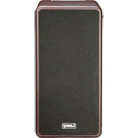
A-DUO - Receiver Laney - Free user manual and instructions
Find the device manual for free A-DUO Laney in PDF.


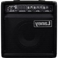
| Brand | Laney |
| Model | A-DUO |
| Category | Acoustic guitar amplifier (receiver) |
| Product type | 2-channel stereo combo amplifier |
| Dimensions (approx.) | 450 x 300 x 250 mm |
| Weight (approx.) | 10 kg |
| Power supply | 100-240 V ~ 50/60 Hz, 100 W |
| Fuse | T3.15A L 250V |
| Inputs | 2 channels (CH1/CH2) combo XLR/6.35 mm jack, 15V phantom power on XLR |
| Auxiliary input | 3.5 mm stereo jack (AUX IN) |
| Outputs | Headphones (3.5 mm jack), XLR balanced D.I. Out with Pre/Post selector and Ground Lift |
| Effects loop | FX Send and Return (6.35 mm jack) |
| Remote pedal | Remote jack for dual FS2 pedal (Reverb/Chorus) |
| Controls | Level with Peak indicator, Volume, Mute, EQ, Shape, Phase, Anti-feedback, Reverb, Chorus |
| Equalization | 4 preset curves: Flat, Bass, Loudness, Vocal |
| Built-in effects | Chorus (adjustable level), Reverb (independent per channel) |
| Anti-feedback | Automatic anti-feedback system |
| Phase inversion | Phase button |
| Safety | Mandatory grounding, moisture protection, spare fuse |
| Maintenance | Clean with a dry cloth |
| Reparability | Refer to a qualified technician |
Frequently Asked Questions - A-DUO Laney
User questions about A-DUO Laney
0 question about this device. Answer the ones you know or ask your own.
Ask a new question about this device
Download the instructions for your Receiver in PDF format for free! Find your manual A-DUO - Laney and take your electronic device back in hand. On this page are published all the documents necessary for the use of your device. A-DUO by Laney.
USER MANUAL A-DUO Laney
natural_image
Exterior view of a beige Laney audio amplifier with sound block and speaker grille (no text or symbols on body)I. COVER PAGE
2. CONTENTS
3. SAFETY WARNINGS (ENGLISH)
4. INTRODUCTION (ENGLISH)
5. ____ QUICK START (ENGLISH)
6. FRONT PANEL CONTROLS (ENGLISH)
7. REAR PANEL CONTROLS (ENGLISH)
8. ____ SAMPLE SETUP / BLOCK DIAGRAM (ENGLISH)
9. SPECIFICATION / FCC COMPLICANCY (ENGLISH)
10-12. FRENCH LANGUAGE
13-15. GERMAN LANGUAGE
16-18. SPANISH LANGUAGE
19-21. PORTUGUESE LANGUAGE
22-23. CHINESE LANGUAGE

ACOUSTIC
IMPORTANT SAFETY INSTRUCTIONS
WARNING: When using electrical products, basic cautions should always be followed, including the following:
-
Read these instructions.
-
Keep these instructions safe.
-
Heed all warnings.
-
Follow all instructions.
-
Do not use this apparatus near water.
-
Clean only with a dry cloth.
-
Do not block any of the ventilation openings. Install in accordance with manufacturer's instructions.
-
Do not install near any heat sources such as radiators, heat registers, stoves or other apparatus (including amplifiers) that produce heat.
-
An apparatus with Class I construction shall be connected to a mains socket outlet with a protective connection. Do not defeat the safety purpose of the polarized or grounding-type plug. A polarized plug has two blades with one wider than the other. A grounding type plug has two blades and a third grounding prong. The wide blade or third prong is provided for your safety. If the provided plug does not fit into your outlet, consult an electrician for replacement of the obsolete outlet.
-
Protect the power cord from being walked on or pinched, particularly at plugs, convenience receptacles, and the point they exit from the apparatus.
-
Only use attachments/accessories provided by the manufacturer.
-
Use only with a cart, stand, tripod, bracket, or table specified by the manufacturer, or sold with the apparatus. When a cart is used, use caution when moving the cart/apparatus combination to avoid injury from tip-over.
-
The mains plug or appliance coupler is used as the disconnect device and shall remain readily operable. The user should allow easy access to any mains plug, mains coupler and mains switch used in conjunction with this unit thus making it readily operable. Unplug this apparatus during lightning storms or when unused for long periods of time.
-
Refer all servicing to qualified service personnel. Servicing is required when the apparatus has been damaged in any way, such as when power-supply cord or plug is damaged, liquid has been spilled or objects have fallen into the apparatus, the apparatus has been exposed to rain or moisture, does not operate normally, or has been dropped.
-
Never break off the ground pin. Connect only to a power supply of the type marked on the unit adjacent to the power supply cord.
-
If this product is to be mounted in an equipment rack, rear support should be provided.
-
Note for UK only: If the colours of the wires in the mains lead of this unit do not correspond with the terminals in your plug, proceed as follows:
a) The wire that is coloured green and yellow must be connected to the terminal that is marked by the letter E, the earth symbol, coloured green or coloured green and yellow.
b) The wire that is coloured blue must be connected to the terminal that is marked with the letter N or the colour black.
c) The wire that is coloured brown must be connected to the terminal that is marked with the letter L or the colour red. 18. This electrical apparatus should not be exposed to dripping or splashing and care should be taken not to place objects containing liquids, such as vases, upon the apparatus.
- Exposure to extremely high noise levels may cause a permanent hearing loss. Individuals vary considerably in susceptibility to noise-induced hearing loss, but nearly everyone will lose some hearing if exposed to sufficiently intense noise for a sufficient time.
The U.S. Government's Occupational Safety and Health Administration (OSHA) has specified the following permissible noise level exposures: According to OSHA, any exposure in excess of the above permissible limits could result in some hearing loss. Earplugs or protectors to the ear canals or over the ears must be worn when operating this amplification system in order to prevent a permanent hearing loss, if exposure is in excess of the limits as set forth above. To ensure against potentially dangerous exposure to high sound pressure levels, it is recommended that all persons exposed to equipment capable of producing high sound pressure levels such as this amplification system be protected by hearing protectors while this unit is in operation.
| Duration Per Day in Hours | Sound Level dBA, slow response |
| 8 | 90 |
| 6 | 92 |
| 4 | 95 |
| 3 | 97 |
| 2 | 100 |
| 112 | 102 |
| 1 | 105 |
| 12 | 110 |
| 14 or less | 115 |
| Intended to alert the user to the presence of uninsulated 'Dangerous Voltage' within the products enclosure that may be sufficient to constitute a risk of electrical shock to persons. Ce symbole est utilise pur indiquer a l'utilisateur de ce produit de tension non-isolee dangereuse pouvant etre d'intensite suffisante pour constituer un risque de choc électrique. Este simbolo tiene el proposito de alertar al usuario de la presencia de '(voltaje) peligroso' que no tiene aislamiento dentro de la caja del producto que puede tener una magnitud suficiente como para constituir riesgo de corrientazo. Dieses Symbol soll den Anwender vor unsolierten gefährlichen Spannungen innerhalb des Gehauses warnen, die von Ausrichender Starke sind, um einen elektrischen Schlag verursachen zu konnen. | |
| Intended to alert the user of the presence of important operating and maintenance (Servicing) instructions in the literature accompanying the product. Dieses Symbol soll den Anwender vor unsolierten gefährlichen Spannungen innerhalb des Gehauses warnen, die von Ausrichender Starke sind, um einen elektrischen Schlag verursachen zu konnen. Este simbolo tiene el proposito de la alertar al usuario de la presencis de instrucciones importantes sobre la operacion y mantenimiento en la literatura que viene conel producto. Dieses Symbol soll den Benutzer auf wichtige Instruktionen in der Bedienungsanleitung aufmerksam machen, die Handhabung und Wartung des Produkts betreffen. | |
| CAUTION: | Risk of electrical shock - DO NOT OPEN. To reduce the risk of electrical shock, do not remove the cover. No user serviceable parts inside. Refer servicing to qualified personnel. |
| ATTENTION: | Risques de choc électrique - NE PAS OUVIRIR Afin de reduire le risque de choc électrique, ne pas enlever le couvercle. Il ne se trouve a l'interieur aucune piece pouvant etre reparee par l'utilisateur. Confler l'entretien a un personnel qualifie. |
| PRECAUCION: | Riesgo de corrientazo - no abra Para disminuir el risego de carrientazo, no abra la cubierta. No hay piezas adentro que el pueda reparar. Deje todo mantenimiento a los tecnicos calificado. |
| VORSICHT: | Risiko - Elektrischer Schlag! Nicht offen! Um das Risiko eines elektrischen Schlages zu vermeiden, nicht die Abdeckung entfernen. Es befinden sich keine Teile darin, die vom Anwender repariert werden Konnten. Reparaturen nur von qualifiziertem Fachpersonal durchführen lassen. |
WARNING:
To prevent electrical shock or fire hazard, do not expose this appliance to rain or moisture. Before using this appliance please read the operating instructions for further warnings.
ADVERTISSEMENT:
After unpacking your amplifier check that it is factory fitted with a three pin 'grounded' (or earthed) plug. Before plugging into the power supply ensure you are connecting to a grounded earth outlet.
If you should wish to change the factory fitted plug yourself, ensure that the wiring convention applicable to the country where the amplifier is to be used is strictly conformed to. As an example in the United Kingdom the cable colour code for connections are as follows.
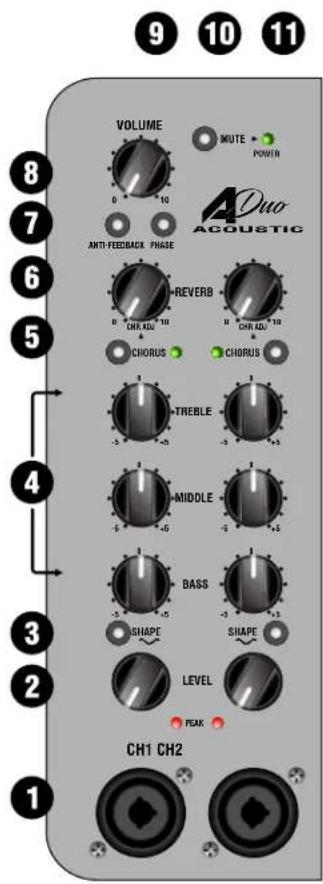
This manual has been written for easy access of information. The front and rear panels are graphically illustrated, with each control and feature numbered. For a description of the function of each control feature, simply check the number with the explanations adjacent to each panel.
Your Laney amplifier has undergone a thorough two stage, pre-delivery inspection, involving actual play testing.
When you first receive your Laney guitar amplifier, follow these simple procedures:
(i) Ensure that the amplifier is the correct voltage for the country it is to be used in.
(ii) Connect your instrument with a high quality shielded instrument cable. You have probably spent considerable money on your amplifier and guitar - don't use poor quality cable it won't do your gear justice.
Please retain your original carton and packaging so in the unlikely event that some time in the future your amplifier should require servicing you will be able to return it to your dealer securely packed.
Care of your Laney amplifier will prolong it's life.....and yours!
WELCOME
Dear Player,
Thank you very much for purchasing your new Laney product and becoming part of the worldwide Laney family. Each and every Laney unit is designed and built with the utmost attention to care and detail, so I trust yours will give you many years of enjoyment.
Laney products have a heritage which stretches back to 1967 when I first began building valve amplifiers in my parents' garage.
Since then we have moved on from strength to strength developing an extensive range of guitar, bass, public address, multi instrument and keyboard amplification products along with a list of Laney endorsees that includes some of the world's most famous and respected musicians.
At the same time we believe we have not lost sight of the reason Laney was founded in the first place - a dedication to building great sounding amplification for working musicians.
Warm Regards,
natural_image
Simple line drawing of a stylized animal or creature (no text or symbols)Lyndon Laney
Chairman and Founder.
INTRODUCTION
Welcome and thank you for choosing the new A-DUO.
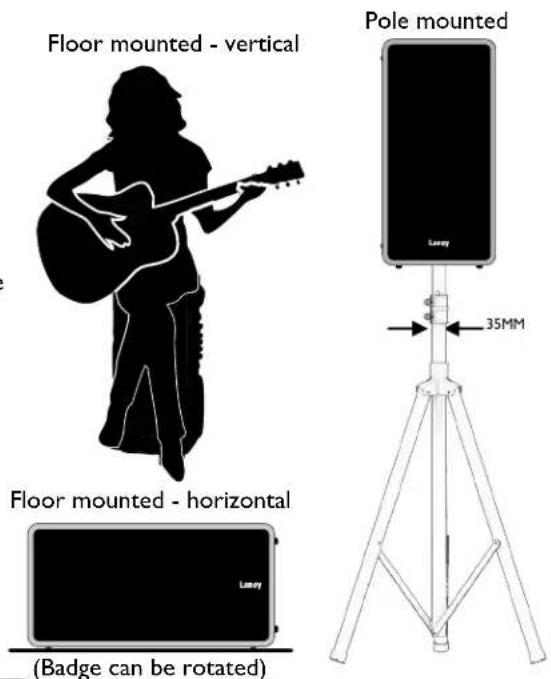
The A-DUO is a professional, compact and portable acoustic guitar amplifier, focussed towards quality performance. Uniquely designed for you to sit on whilst playing, the control panel is placed to be easily accessible during your performance.
The A-DUO is equipped with two independent channels capable of accepting either XLR or Jack inputs via the XLR combi inputs so whatever output system your acoustic guitar has the A-DUO has it covered. With a high quality on-board Reverb and Chorus the A-DUO lets you choose to enhance your guitar sound without losing any of the quality of your original guitar tone.
Although designed primarily for acoustic guitar the A-DUO is equally at home handling a keyboard or a vocal mic, making the
A-DUO ideally suited as a small PA system for party jams or intimate performances.
Please continue to read the rest of this manual as it is the key to getting the best out of your A-Duo.
QUICK START
I. CONNECT
Guitar, ukulele, banjo, mandolin or violin for example.
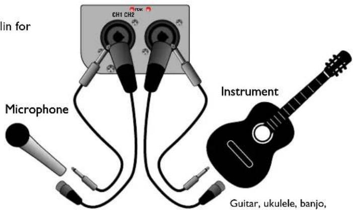
Guitar, ukulele, banjo, mandolin or violin for example.
2. POWER-UP

3. SET LEVELS:
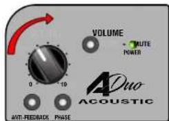
Slowly increase the Level control until the Peak led begins to flash during the loudest peaks of the music.
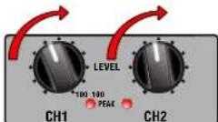
Increase the Volume control until the required listening level is achieved.
4. ADD EQ:
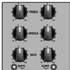
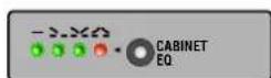
Fine tune your sound with the 3-band EQ and Shape control, add to the overall tone with Cabinet EQ (17), or experiment with a mixture of the three.
5. ADD FX
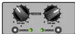
If required, add independently assignable Chorus and Reverb.
FRONT PANEL CONTROLS
I. CHI/CH2 MIC/LINE INPUT: Combi sockets provide the flexibility to connect either a balanced XLR or unbalanced jack terminated cable. Set Level control (2) to minimum before connecting a device to the Mic/Line inputs. For best results, always use a good quality instrument/mic cable.
Phantom Power (15V non switchable) is available from the XLR Inputs only. This is for use with condenser microphones, but dynamic mic's won't be damaged if used. Please note that some 48V condenser Mics may not work.
- LEVEL/PEAK: Use together to find the optimum level for your signal. Adjust the Level so the Peak only lights during the very highest peaks of the connected signal.
Peak illuminates constantly = possible distortion. Damage won't occur to the amplifier, but audio quality may suffer.
Peak is never illuminated = slightly reduced signal to noise ratio as amplifier is not running at optimum levels.
-
SHAPE: Engages an EQ circuit to give a brighter, more extended top end and scooped mid to provide more definition.
-
EQ: A traditional set of tone controls giving the player a natural set of tools to shape their ideal sound. As a starting point, set the EQ controls to the 0 position.
-
CHORUS: To engage the Chorus press the Chorus switch. The adjacent LED lights only when the effect is active. To adjust the chorus amount, press and hold the Chorus switch (while the chorus is active) and adjust using the Reverb control. Once you release the Chorus switch, the LED will briefly flash to indicate the setting has been stored.
The amplifier is shipped with a Chorus level of 3.
- REVERB LEVEL: Use these to independently control the reverb/chorus for channels 1 and 2. The Reverb Level increases progressively as you move the control from 0 to 10.
TIAso controls Chorus Level.
flowchart
graph TD
    A["Speaker"] --> B["Amplifier"]
    C["Guitar"] --> B
    D["Waveform"] --> B
    B --> E["Output"]
    style A fill:#f9f,stroke:#333
    style C fill:#ccf,stroke:#333
    style D fill:#cfc,stroke:#333
    style E fill:#fcc,stroke:#333
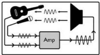
Audio feedback is caused when a loop occurs between a microphone or guitar pickup and the loudspeaker. Commonly caused by pointing a microphone at a speaker or simply by the two being too close. The result is an unpleasant screeching or whistling sound. The A-Duo is equipped to deal with this.
- ANTI-FEEDBACK: When the Anti-Feedback control is enabled the A-Duo actively and automatically searches for any signs of feedback (over multiple frequencies) and eliminates it before becoming a serious problem.
If you have microphones connected, enable the Anti-Feedback.
-
PHASE SWITCH: Inverts the phase of the signal from the amplifier output. When you play any acoustic guitar the sound it produces is a waveform, the same applies to an acoustic guitar plugged into an acoustic amplifier. It is not uncommon for these two waveforms to be out of phase with each other. To a player sat close to an amplifier this poses a small problem if the wave forms are out of phase as they are destructive to each other and cancel each other out. This would cause the guitar to sound a little thin and lack-lustre. Engaging the phase switch switches the phase of the amplified signal removing the problem of destructive interference. However sometimes the low frequencies being in phase can cause acoustic feed back problems, to avoid this try operating the phase reversal switch. Most times this will cure the problem. One thing to point out is that the audience does not hear any phase problems as by the time the sound wave reaches them any phase differences have been cancelled out naturally.
-
VOLUME: To control the overall output level from the loudspeaker, phones, FX Send and D.I. Out.
-
MUTE: This will mute CHI and 2, but not signals connected to AUX IN or FX RETURN.
The Power Led will flash when the Mute is enabled.
II. POWER: Illuminates when the Power Switch is set to I.
REAR PANEL
- PHONES: For silent practice or late night playing just connect your favourite headphones to the 3.5mm jack socket.
When headphones are connected, the internal loudspeakers are automatically turned off.
-
AUX IN: Play along to your favourite tracks by connecting a MP3 player (or any other line level device) using a stereo 3.5mm jack.
-
FX LOOP: Gives you the option to route the pre-amp signal through an additional FX unit. This could be in addition to or as an alternative to the onboard FX.
-
REMOTE: Connect an FS2-Mini (2-way) foot switch and independently control Reverb and Chorus remotely.
RING: Chorus
TIP: Reverb
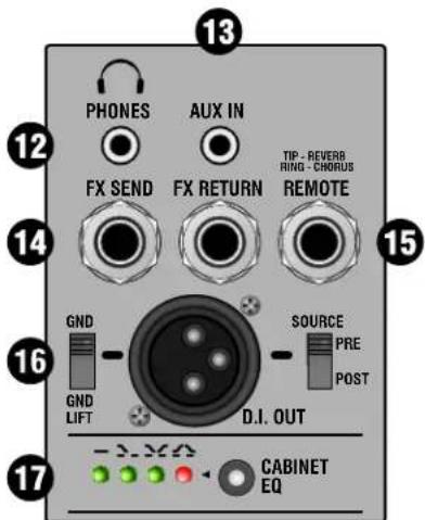
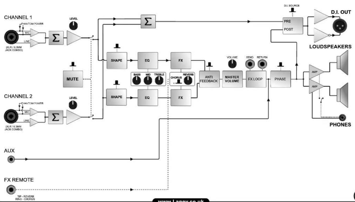
- D.I. OUT: This socket provides a balanced output for direct injection of the amplifier signal into a mixing desk mic input. Using the Source switch, choose if the signal is Pre or Post EQ, FX and Mute. Refer to the block diagram on page 8. Note: the DI out level is nominal 500mV.
Finally, a ground lift switch is also provided to reduce the possibility of earth loop induced hum (when connecting to other equipment).
- EQ: This dual function switch allows you to select one of four pre-defined EQ curves allowing you to adjust the tonal balance. To toggle from one to the next simply press the switch momentarily. An adjacent LED will clearly indicate what's selected. The EQ setting will be stored in memory, ready for use next time.
Flat: General purpose EQ setting - ideal for floor use.
Bass: An increase in the low frequency content of your audio. Ideal when the A-Duo is pole mounted to compensate for bass loss.
Loud: An increase in both low and high frequencies. Ideal for pole mounted use with added definition.
Vocal: Decreases the amount of bass and emphasises the vocal content. Also ideal for outdoors.
18. MAINS INLET AND POWER SWITCH:
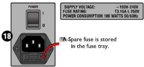
A Universal mains input for worldwide usage without the need to change anything except your power cord and fuse rating. The fuse rating will be correct for the country in which the unit was sold. If used else where, check the fitted fuse is of the correct rating. See information on A-Duo rear panel.
The unit must be earthed under all circumstances!
Set Power switch to the off position (0) and disconnect the power connector when the amplifier is not in use.
USING THE A-DUO
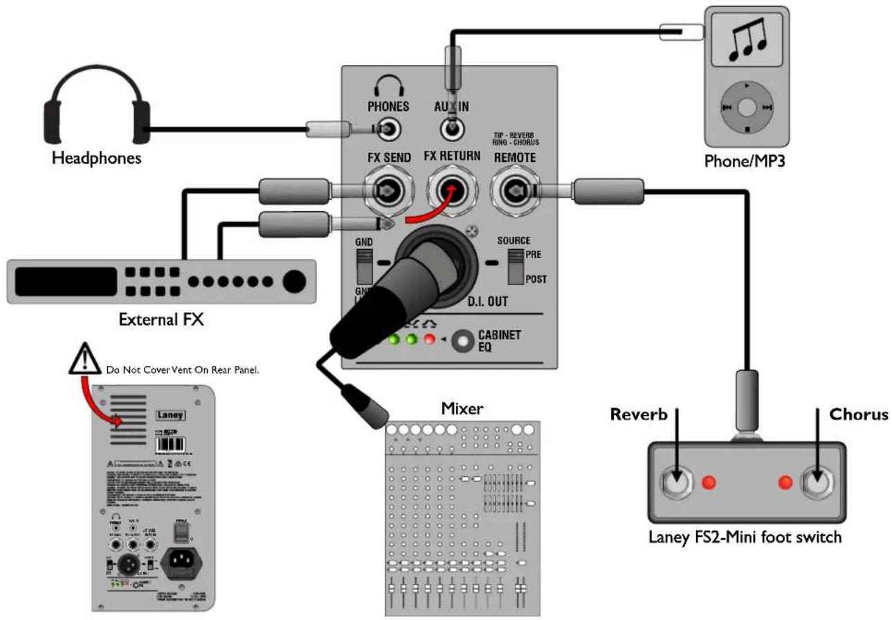
SAMPLE SETUP
CONNECTION IDEAS:
flowchart
graph TD
    A["Headphones"] --> B["FX SEND"]
    B --> C["FX RETURN"]
    C --> D["TIP - REVERB RING - CHORUS"]
    D --> E["REMOTE"]
    E --> F["Phone/MP3"]
    G["External FX"] --> H["GND"]
    H --> I["SOURCE"]
    I --> J["PRE POST"]
    J --> K["D.I. OUT"]
    L["Mixer"] --> M["CABINET EQ"]
    N["Reverb"] --> O["Laney FS2-Mini foot switch"]
    P["Chorus"] --> Q["Phone/MP3"]
(External devices shown in the diagram are not included within the A-Duo package.)
BLOCK DIAGRAM
flowchart
graph TD
    subgraph CHANNEL 1
        A["Channel 1: (DLR / 6.3MM JACK COMBO)"]
        B["Channel 1: PHANTOM POWER MIC"]
        B --> C["Σ"]
        C --> D["MUTE"]
        D --> E["LEVEL"]
        E --> F["Σ"]
        F --> G["PRE POST"]
        G --> H["D.I. OUT"]
        I["Channel 2: (DLR / 6.3MM JACK COMBO)"]
        J["Channel 2: PHANTOM POWER MIC"]
        J --> K["Σ"]
        K --> L["MUTE"]
        L --> M["LEVEL"]
        M --> N["SHAPE"]
        N --> O["EQ"]
        O --> P["FX"]
        P --> Q["CHORUS REVERS"]
        Q --> R["FX"]
        R --> S["ANTI FEEDBACK"]
        S --> T["MASTER VOLUME"]
        T --> U["FX LOOP"]
        U --> V["PHASE"]
        V --> W["LOUDSPEAKERS"]
        X["AUX"] --> Y["TIP - REVERB RING - CHORUS"]
    end

    subgraph CHANNEL 2
        Z["AUX"] --> AA["TIP - REVERB RING - CHORUS"]
    end

    C --> AB["LEVEL"]
    AB --> AC["SHAPE"]
    AC --> AD["EQ"]
    AD --> AE["FX"]
    AE --> AF["CHORUS REVERS"]
    AF --> AG["FX"]
    AG --> AH["ANTI FEEDBACK"]
    AH --> AI["MASTER VOLUME"]
    AI --> AJ["FX LOOP"]
    AJ --> AK["PHASE"]
    AK --> AL["LOUDSPEAKERS"]
    AL --> AM["D.I. SOURCE"]
    AL --> AN["MONITOR"]
    AL --> AO["THYPOLE"]
    AL --> AP["THYPOLE"]
    AL --> AQ["THYPOLE"]

    F --> AR["Σ"]
    AR --> AS["D.I. SOURCE"]
    AS --> AT["PRE POST"]
    AT --> AU["D.I. OUT"]
    AU --> AV["LOUDSPEAKERS"]
    AV --> AW["D.I. OUT"]
    AV --> AX["MONITOR"]
    AV --> AY["THYPOLE"]
    AV --> AZ["THYPOLE"]

    subgraph CHANNEL 1
        BA["Channel 1: (DLR / 6.3MM JACK COMBO)"]
        BB["Channel 1: PHANTOM POWER MIC"]
        BC["Channel 1: LINE"]
        BD["MUTE"] --> BE
    end

    subgraph CHANNEL 2
        BF["Channel 2: (DLR / 6.3MM JACK COMBO)"]
        BG["Channel 2: PHANTOM POWER MIC"]
        BH["Channel 2: LINE"]
        BI["MUTE"] --> BJ
    end

    subgraph CHANNEL 1
        BK["Channel 1: (DLR / 6.3MM JACK COMBO)"]
        BL["MUTE"] --> BM
        BN["MUTE"] --> BO
    end

    subgraph CHANNEL 2
        BP["Channel 2: (DLR / 6.3MM JACK COMBO)"]
        BQ["Channel 2: PHANTOM POWER MIC"]
        BR["MUTE"] --> BS
        BT["MUTE"] --> BT
    end

    subgraph CHANNEL 2
        BU["Channel 2: (DLR / 6.3MM JACK COMBO)"]
        BV["MUTE"] --> BW
        BX["MUTE"] --> BX
        BY["MUTE"] --> BY
    end

    subgraph CHANNEL 2
        BW
        BX
        BY
    end

    subgraph CHANNEL 2
        BW
        BX
        BY
    end

    subgraph CHANNEL 2
        BW
        BX
        BY
    end

    subgraph CHANNEL 2
        BW
        BX
        BY
    end

    subgraph CHANNEL 2
        BW
        BX
        BY
    end

    subgraph CHANNEL 2
        BW
        BX
        BY
    end

This device complies with Part 15 of the FCC rules.
Operation is subject to the following two conditions:
1) This device may not cause harmful interference
2) This device must accept any interference received, that may cause undesired operation.
Warning: Changes or modification to the equipment not approved by Laney can void the user's authority to use the equipment.
Note: This equipment has been tested and found to comply with the limits for Class B digital device, pursuant to Part 15 of the FCC Rules. These limits are designed to provide reasonable protection against harmful interference in a residential installation. This equipment generates, uses and can radiate radio frequency energy and if not installed and used in accordance with the instructions, may cause harmful interference to radio communications. However, there is no guarantee that interference will not occur in a particular installation. If this equipment does cause harmful interference to radio or television reception, which can be determined by turning the equipment off and on, the user is encouraged to try and correct the interference by one or more of the following measures.
•Reorient or relocate the receiving antenna.
- Increase the separation between the equipment and receiver.
- Connect the equipment into an outlet on a circuit different from that to which the receiver is connected.
- Consult the dealer or an experienced radio/TV technician for help.

This product conforms to the requirements of the following European Regulations, Directives & Rules:
CE Mark (93/68/EEC), Low Voltage (2014/35/EU), EMC (2014/30/EU),
RoHS (EU2011/65/EU), ErP (2009/125/EU).

In order to reduce environmental damage, at the end of its useful life, this product must not be disposed of along with normal household waste to landfill sites. It must be taken to an approved recycling centre according to the recommendations of the WEEE (Waste Electrical and Electronic Equipment) directive applicable in your country.
[EMPTY]
requirements of the following European Regulations, Directive
Itage (2014/35/EU), EMC (2014/30/EU),
2009/125/EU).
| Model: | A-DUO | |
| Supply Voltage: | ~100V to ~240V 50-60Hz | |
| Mains Fuse: | T3.15A L 250V | |
| Power Consumption: | 100W | |
| Output Power Rating: | 120W | |
| Loudspeakers: | 2 x 8" Custom Designed Full Range Coaxial Driver | |
| Inputs: | CH1/CH2 - Combi Balanced XLR | Supports 15V Phantom Power |
| CH1/CH2 - Mic/Line - Unbalanced 6.3mm jack | Impedance - 10M Ohm/47pF | |
| CH1/CH2 - Mic/Line - Combi Balanced XLR | Supports 15V Phantom Power | |
| Unbalanced 6.3mm jack | Impedance - 10M Ohm/47pF | |
| EQ: | Bass: | ±12dB at 100Hz, Lo Shelving |
| Middle: | ±12dB at 600Hz, Peaking | |
| Treble: | ±12dB at 10KHz, Hi Shelving | |
| Shape: 3 Band Preshape EQ | ||
| FX Channel1: | Reverb: Adjustable amount | |
| Chorus: Adjustable amount | ||
| FX Channel2: | Reverb: Adjustable amount | |
| Chorus: Adjustable amount | ||
| Other: | Anti-Feedback control | Auto 12 Position notch filter |
| Phase | ||
| D.I. Out: | Balanced XLR with source switch and GND lift | |
| Aux In: | 3.5mm Stereo jack | |
| Headphones: | 3.5mm Stereo jack | |
| (Speaker mutes when headphones are connected) | ||
| Pole cup: | For use with a standard 35mm pole stand (not included) | |
| Unit dimensions (HWD): | 530 x 265 x 242mm, 20.9" x 10.4" x 9.5" | |
| Net weight: | 10.5Kg, 23.1 lbs | |
| Carton dimensions (HWD): | 615 x 310 x 285mm, 24.2" x 12.2" x 11.2" | |
| Gross weight: | 12Kg, 26.5 lbs | |
| Optional Extras: | FS2-Mini Foot switch PN: FS2-MINI | |
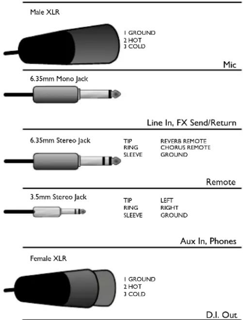
In the interest of continued development, Laney reserves the right to amend product specification without prior notification.
CONSIGNES DE SÉCURITÉ IMPORTANTES
Ring: Chorus Tip: Reverb
natural_image
Three-step diagram showing a device being rotated into a pentagonal frame, with no text or symbols present.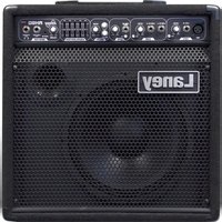
Brand : Laney
Model : A-DUO
Category : Receiver