
Shrinkfast H-950 - Heat gun Uline - Free user manual and instructions
Find the device manual for free Shrinkfast H-950 Uline in PDF.

User questions about Shrinkfast H-950 Uline
0 question about this device. Answer the ones you know or ask your own.
Ask a new question about this device
Download the instructions for your Heat gun in PDF format for free! Find your manual Shrinkfast H-950 - Uline and take your electronic device back in hand. On this page are published all the documents necessary for the use of your device. Shrinkfast H-950 by Uline.
USER MANUAL Shrinkfast H-950 Uline
natural_image
Line drawing of a mechanical tool or device with a handle and spout (no text or symbols)SAFETY
Read these instructions thoroughly to familiarize yourself with the parts and safe operation of this tool. Keep for future reference.
- Never point the gun at another person.
- Inspect hose before each use.
• Always shut off valve at tank when leaving gun unattended for any length of time. -
Safety trigger mechanism automatically shuts off if gun is dropped.
-
Wear heat-resistant gloves and safety glasses when using the gun.
- Ensure adequate ventilation when using indoors.
- Ensure wire guard is in place before use.

WARNING! BURN DANGER. Do not touch wire guard after gun has been used.
SPECIFICATIONS
| DISTANCE (FT.) | TEMPERATURE (°F) |
| 0 3,200 | |
| 1/2 1,120 | |
| 1 650 |
Heat Capacity: 172,500 BTU/hr
Velocity (6" from tip of flame): 2,100 ft/min
Propane Consumption: 8.0 lbs./hr
Operating Pressure (Preset): 22.5 PSIG
Weight: 2 lbs. 20 oz.
Air Consumption: 30 cfm
Emissions: .015 CO/CO _2
GENERAL INFORMATION
SHRINK FILM
Use only with shrink film (not all plastic films are shrink film). Shrink film should be virgin plastic, not reprocessed material. For light loads of 100 lbs. or less, 3 mil thick film should work. For heavy weights or items (example, steel drums at 2,000 lbs./pallet), use 6 mil or thicker shrink film.
- Gusseted film shrinks equally in both directions, and tends to pull up and away from pallet. Length should be longer than the height of the pallet.
- Centerfold film shrinks mainly in one direction and has a reduced tendency to pull up off of pallet.
SHRINK BAG
Most bags list lay-flat length and width. To determine what size bag you need, use the following example:
Load size: 47 x 30 x 36" (L x W x H)
Calculate the width of bag:
- Add the width and length 30 + 47" = 77"
- Add fitting allowance (4" to allow for ease of fit) 4 + 77" = 81" (This is the width bag you'll need.)
Calculate the length of the bag:
- Use 1/2 the length of the shorter side 1/2 of 30" = 15"
- Add number from step 1 to height 15 + 36" = 51"
- Add shrink allowance (1" for each foot of height) 36" = 3', so 3" shrink allowance 51 + 3" = 54" (This is the length bag you'll need.)
- Bag size is 54 x 81" (L x W).
PROPANE TANK

WARNING! Use only with vapor withdrawal propane tanks. NEVER attach heat gun to a liquid withdrawal propane tank.

WARNING! Using a liquid withdrawal propane tank clogs the orifice filter and may result in an extremely dangerous long flame.
Tanks are available in 6, 8, 10, 20, 30 and 40 lb. sizes. 6 lb. tanks are adequate for intermittent use. Use larger tanks for continuous use.
Tank Pressure – Depends on tank temperature. At 72^ F, pressure is 110 psi; at 0^ F, pressure drops to 22 psi. When in use, tank pressure drops due to evaporation process of converting liquid propane to propane gas. Tank may drop to 0^ F with ice appearing on the outside. Propane pressure may drop below 15 psi.

WARNING! DO NOT run the gun when tank pressure drops below 15 psi.
- For continuous operation, use multiple tanks, switching the gun from one to another.
- Using an ordinary desk fan to blow air on the tank will prevent it from icing up.
VENTILATION
When in use, this heat gun produces carbon dioxide, carbon monoxide and water vapor.

WARNING! Prolonged exposure to carbon monoxide (CO) is lethal. Provide adequate ventilation when gun is used indoors.
To maintain a safe CO concentration (50 parts per million as set by OSHA Standard 1910.93), ventilation requirements are 2,000 cu. ft./min. of fresh air while gun is operated at maximum operating pressure of 30 psi.
Ventilation capacity should be sized proportionally for different production rates.

EXAMPLE: Based on a 1½ minute heating cycle per pallet, fresh air requirements are 3,000 cu. ft./pallet. If the production rate is 10 pallets/hour, a ventilation system needs to provide 500 cu. ft./minute.
In areas where ventilation is provided by open doors or windows, safe CO levels will be maintained as long as room temperature does not exceed 150^ F.
OPERATION
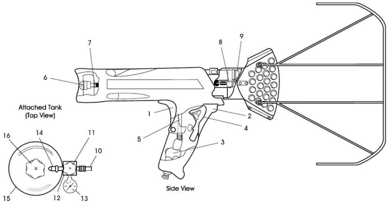
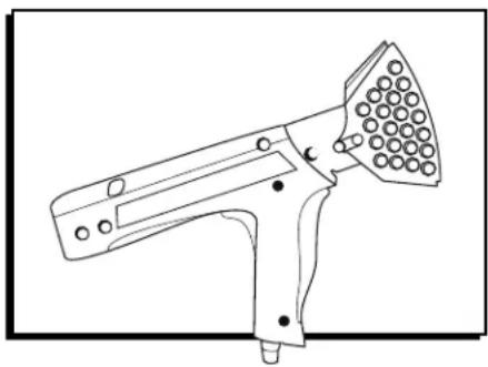
PARTS AND FUNCTIONS
text_image
Attached Tank (Top View) 16 14 11 10 15 12 13 7 6 8 9 1 2 4 5 3 Side View| # | PART FUNCTION | |
| 1 | Safety Trigger Prevents | accidental gas release. |
| 2 | Gas Handle Actuates | gas valve and igniter. |
| 3 | Gas Valve Opens fuel | flow. |
| 4 | Igniter Fire piezoelectric | spark igniter. |
| 5 | Fuel Line Carries fuel to orifice. | |
| 6 | FilterPrevents clogging. | |
| 7 | OrificeMeters fuel. | |
| 8 | Spark Plug | Ignites fuel/air mixture. |
| 9 | Flame HolderPrevents flashback and flame out. | |
| 10 | Hose | Connects regulator and gun. |
| 11 | Regulator | Regulates pressure to gun. |
| 12 | Adjustment Screw | Sets pressure. |
| 13 | Pressure Gauge | Indicates line pressure. |
| 14 | Prest-o-Lite Fitting | Connects and contains excess fuel check valve. |
| 15 | Tank | Sold separately, see tank info |
| 16 | Tank Valve | Opens/closes fuel supply. |
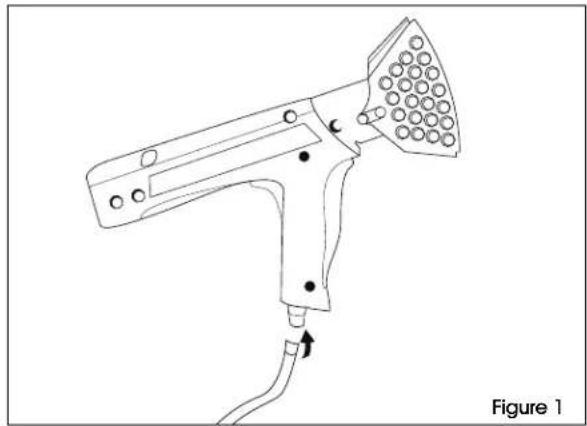
CONNECTIONS
-
Connect gun, hose and regulator to the tank. Use a wrench to tighten fittings (left-hand threaded). (See Figure 1)
-
Check for leaks.
-
Open tank valve without pushing trigger to pressurize the hose. Pressure gauge should read 15 to 30 psi when gun is not in use.
- Close tank valve and check pressure gauge. Rapid pressure loss indicates a leak. Check all connections.
natural_image
Line drawing of a handheld electric shaver with a probe inserted, labeled Figure 1 (no text or symbols on the diagram itself)OPERATION CONTINUED
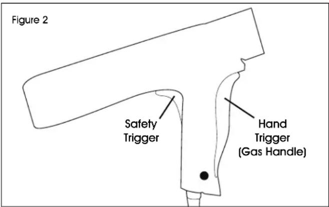
START-UP
Open the tank valve and wait 5 seconds to fully pressurize hose. You will hear the flow check valve open with an audible click.
- Press the safety trigger. This prevents the gas handle from opening accidentally. (See Figure 2)
text_image
Figure 2 Safety Trigger Hand Trigger (Gas Handle)- Slowly squeeze the gas handle until the igniter fires with an audible click. (See Figure 2)

CAUTION! Gun will ignite.

IMPORTANT:
- Squeezing the gas handle too quickly will cause the igniter to fire the spark plug before the gas mixture is ready.
- If gun fails to fire fully, release BOTH the safety trigger and gas handle to reset the igniter. Then repeat the starting procedure.
- For thinner films, set the regulator for lower pressure and adjust up for thicker films. Factory preset is 22 psi.
USING THE HEAT GUN
Use gun only in well-ventilated areas.

WARNING! Do not operate gun in areas with flammable gases or where smoking is prohibited.
IMPORTANT HEAT SHRINK TIPS:
- Heat only softens film. Shrinking occurs as film cools. Do not concentrate heat and wait for film to shrink. Keep the gun moving.
- Ensure the four corners of the bag are wrapped under pallet.
PALLETIZING
- Elevate pallet load approximately 6" from floor. Leave area under the four corners clear.
- Carefully fit pallet bag over load. Do not puncture or tear the bag. Bag should fit snugly over the load and overlap the base of the pallet almost to the floor.
-
Shrink Bottom: Ignite gun and hold about 12" from film.
a. Move around pallet, applying heat to the bottom edge of the bag and blow it under the pallet.
b. Shrink film to grip bottom of pallet firmly, locking bag to pallet and unitizing load. -
Shrink Sides: Do one side at a time.
a. Holding gun 12" from film, shrink side by sweeping gun smoothly across the bottom edge.
b. Move up one foot and sweep back, continue to move up and sweep across the side until you reach the top.

IMPORTANT! Keep gun moving at all times.
c. Repeat for the remaining sides.
- Shrink Top: Since top is already pulled taut by the four sides being shrunk, this requires less heat than shrinking the sides.
PATCHING
Patch holes easily: Lay a square of film over the hole and apply heat to the edges to weld patch to bag. Also useful for reinforcing edges or corners.
SHRINK WRAPPING LARGE OR ODD-SHAPED LOADS
Wrap objects too big to fit under a bag by joining several sheets of shrink film together.
- Adjoining sheets should overlap 18".
- Secure sheets using the weight of the load at the base or with battens tacked to the skids.
MAINTENANCE

NOTE: Grease all O-rings for easier assembly. Hose adapter fitting is glued permanently into the valve body.Filter Cleaning
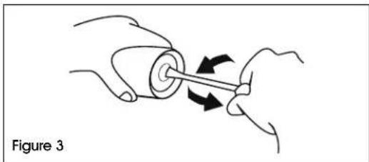
FILTER CLEANING
- Unscrew the filter holder using a screwdriver or coin. Pull out filter holder. (See Figure 3)
natural_image
Illustration of hands holding a cylindrical object with arrows indicating motion or force direction (no text or symbols)- Remove filter screen/spring assembly. Clean with compressed air or replace. (See Figure 4)
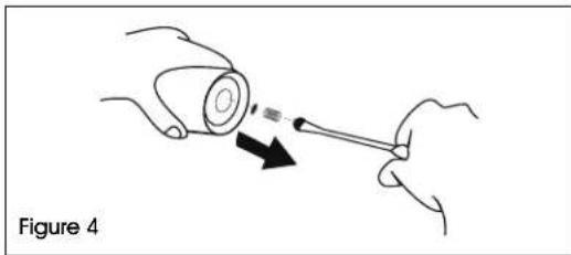
natural_image
Illustration of a hand holding a cylindrical object with a pointer and arrow indicating motion (no text or symbols)VALVE TIMING ADJUSTMENT
- Gas valve opening is adjusted by the adjustment screw. (See Figure 5)
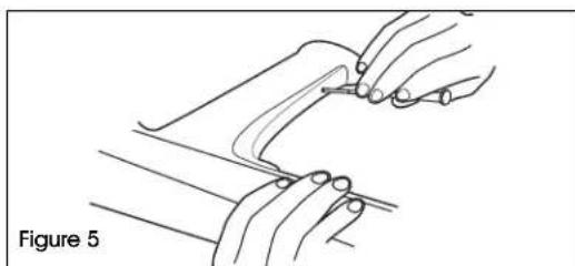
natural_image
Line drawing of a hand holding a tool, labeled Figure 5 (no text or symbols on the diagram itself)- It should be set so the valve opens when the gas handle is depressed half way.
REPLACE SPARK PLUG
- Depress button and remove combustor assembly. (See Figure 6)
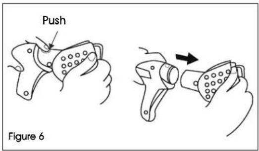
text_image
Push Figure 6- Remove spark plug and flame holder with pliers. (See Figure 7)
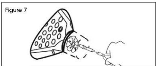
natural_image
Diagram of a syringe with a hand pulling it, labeled 'Figure 7' (no text or symbols on the diagram itself)- Unscrew spark plug. Set new spark plug gap to 3-5 mm. (See Figure 8)
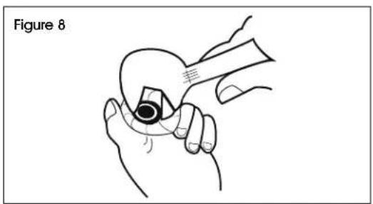
text_image
Figure 8 手MAINTENANCE CONTINUED
REPLACE IGNITER
- Remove five mounting screws and remove right side of housing. (See Figure 9)
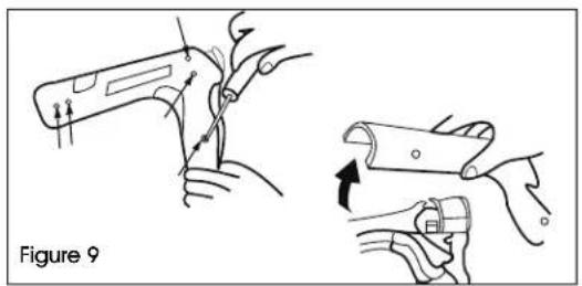
natural_image
Illustration of two hands holding a tool, one with arrows indicating movement or force, the other showing a curved tool (no text or symbols)- Remove retaining screw holding the cable and the contact spring. (See Figure 10)
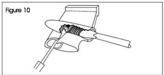
natural_image
Technical line drawing of a mechanical component with internal spring and lever mechanism (no text or symbols)- Use a screwdriver to snap off the clamp. (See Figure 11)
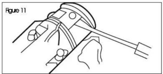
natural_image
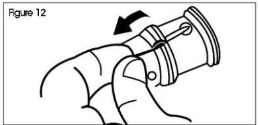
Technical line drawing of a mechanical assembly with no visible text or symbols- Pull cable out. (See Figure 12)
natural_image
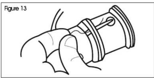
Diagram of a mechanical component with an arrow indicating rotation, labeled 'Figure 12' (no text or symbols on the diagram itself)- Untie and remove ground strap. (See Figure 13)
natural_image
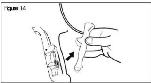
Line drawing of a mechanical assembly with no visible text or symbols- Lift out trigger assembly. (See Figure 14)
natural_image
Diagram showing a hand holding a tool with an arrow indicating a step, labeled 'Figure 14' (no text or symbols on the diagram itself)CLEAN OR REPLACE ORIFICE

IMPORTANT! The orifice consists of six slender, thin-walled tubes that are easily bent or damaged. Once bent or damaged, gun performance is seriously impaired. Perform the following procedure with extreme care.
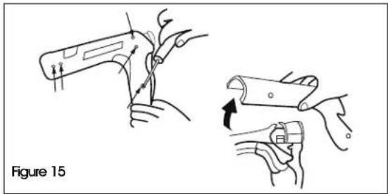
- Remove five mounting screws and remove right side of housing. (See Figure 15)
natural_image
Illustration of two hands holding a tool, showing a close-up and a magnified view of the tool being adjusted (no text or symbols present)MAINTENANCE CONTINUED
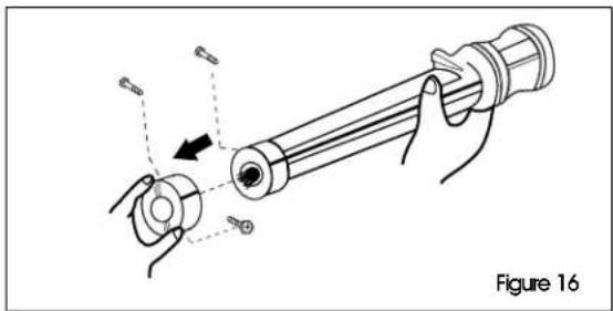
- Remove the three screws holding the pump. (See Figure 16)
- Remove pump by sliding it away from the orifice, then lift it out. (See Figure 16)

CAUTION! Lifting the pump before sliding it away will damage the orifice tubes.
natural_image
Diagram of a mechanical tool with hands operating a cylindrical component, showing motion direction (no text or symbols)- Unscrew the orifice. (See Figure 17)
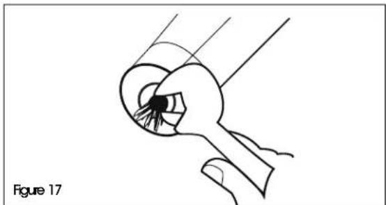
natural_image
Line drawing of a hand holding a tool with a pointed tip, labeled 'Figure 17' (no text or symbols on the diagram itself)- Use a 0.6 mm drill bit to clean out each orifice. (See Figure 18)
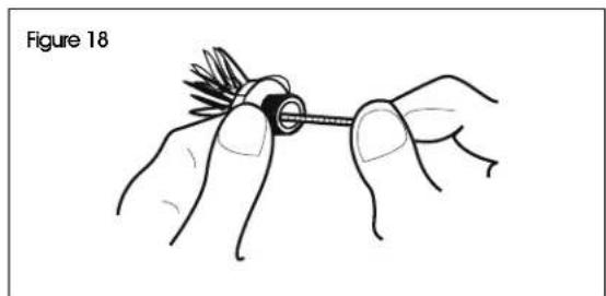
natural_image
Illustration of hands holding a small mechanical component, labeled 'Figure 18' (no text or symbols on the diagram itself)SAFETY CAGE MOUNTING
- Push both curved tubular joints onto one half of the safety cage. (See Figure 19)
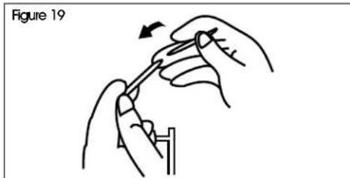
natural_image
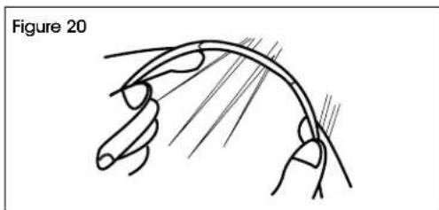
Illustration of hands using a tool to adjust or install a component, labeled 'Figure 19' (no text or symbols on the diagram itself)- Insert the other half of the safety cage into the tubular joints and twist together until mounting struts on both halves are parallel. (See Figure 20)
natural_image
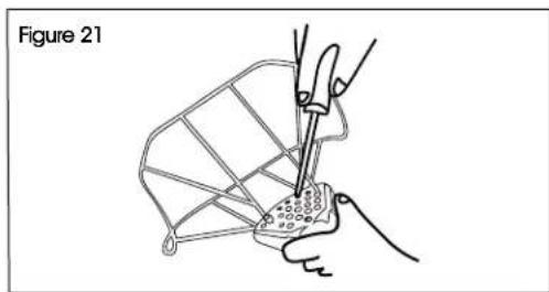
Diagram of a human hand with fingers and eyelids, labeled 'Figure 20' (no text or symbols on the diagram itself)- Attach cage assembly to the combustor using four mounting screws. (See Figure 21)
natural_image
Illustration of hands using a tool to adjust or install a component, no text or symbols presentTROUBLESHOOTING

NOTE: Check tank first – Majority of problems are caused by using a liquid withdrawal tank instead of a vapor withdrawal tank.
| OPERATING ISSUE CAUSES RECOMMENDATIONS | ||
| Gun will not fire. | Handle not fully depressed.Handle depressed too quickly.Pressure too low.Handle not released fully.Spark plug needs to be replaced.Gas not turned on. | Depress handle all the way until the igniter fires. Listen for a click.Slowly squeeze handle to ensure mixture enters combustor before firing.Check regulator.Release handle and safety triggers to reset igniter.Replace spark plug using the instructions included.Check On/Off valve. |
| Combustor turns red.*(insufficient fuel flow) | Wrong fuel.Tank used up and tank pressure is below 15 PSIG.Excess flow check valve not open.Clogged orifice and/or filter.Clogged hose.Clogged fuel line. | Check fuel type.Switch to new tank.Open tank valve and wait 10 seconds until hose is pressurized before using gun.Remove and clean with compressed air.Blow or replace.Blow out or replace. |
| Large flame-fuel flow. | Leak in orifice assembly.Wrong pressure. | Tighten orifice in holder and check.Reset to 15-30 PSIG. |
* Leading edge of combustor turns red under normal conditions. More than 1" of combustor turning red indicates trouble.
natural_image
Line drawing of a mechanical tool or device with a central handle and multiple circular components (no text or symbols)SEGURIDAD
natural_image
Line drawing of a handheld electric shaver with a probe inserted, labeled 'Diagrama 1' (no text or symbols on the diagram itself)natural_image
Illustration of hands using a tool to interact with a cylindrical object, labeled 'Diagrama 3' (no text or symbols on the diagram itself)natural_image
Line drawing of two hands holding a tool, labeled 'Diagrama 5' (no other text or symbols)natural_image
Technical line drawing of a mechanical component with no visible text or symbolsnatural_image
Diagram of a hand holding a cylindrical tool with a separate mechanical component, showing no text or symbols.natural_image
Line drawing of a hand holding a small object, labeled 'Diagrama 17' (no other text or symbols)natural_image
Line drawing of a mechanical tool or device with a central handle and multiple circular components (no text or symbols)SÉCURITÉ
natural_image
Line drawing of a handheld device with circular components and a cable, labeled Figure 1 (no text or symbols on the device itself)FONCTIONNEMENT SUITE
DÉMARRAGE
natural_image
Illustration of hands using a tool to adjust a cylindrical object with directional arrows (no text or symbols)natural_image
Illustration of hands holding a cylindrical object with an arrow indicating direction, labeled 'Figure 4' (no text or symbols on the diagram itself)RÉGLAGE DE LA SOUPAPE
natural_image
Line drawing of two hands holding a piece of paper or tool, labeled 'Figure 5' (no other text or symbols)text_image
Appuyer Figure 6natural_image
Line drawing of a handheld device with a hand holding a tool, labeled 'Figure 7' (no text or symbols on the device itself)natural_image
Illustration showing two hands performing a manual manipulation or tooling procedure, with no visible text or symbols.natural_image
Technical line drawing of a mechanical component with internal spring and lever mechanism (no text or symbols)natural_image
Technical line drawing of a mechanical assembly with no visible text or symbolsnatural_image
Diagram of a hand gripping a mechanical component with a directional arrow indicating motion (no text or symbols)natural_image
Technical line drawing of a mechanical component with no visible text or symbolsnatural_image
Illustration of a hand holding a tool with an arrow indicating motion, no text or symbols presentNETTOYER OU REMPLACER L'ORIFICE

natural_image
Illustration of two hands holding a tool, showing step-by-step assembly (no text or symbols)ENTRETIEN SUITE
natural_image
Diagram of a mechanical device with hands and arrows indicating motion, labeled Figure 16 (no text or symbols on the diagram itself)natural_image
Line drawing of a hand holding a small object with a pointed tip, labeled 'Figure 17' (no text or symbols on the diagram itself)natural_image
Illustration of hands holding a screwdriver with a spool, labeled Figure 18 (no text or symbols on the diagram itself)INSTALLATION DE LA CAGE DE SÉCURITÉ
natural_image
Illustration of hands using a tool to adjust or install a component, labeled 'Figure 19' (no text or symbols on the diagram itself)natural_image
Diagram of a curved biological structure with branching patterns, labeled 'Figure 20' (no text or symbols on the diagram itself)natural_image
Line drawing of a hand using a tool to wire a small object on a grid-patterned surface, labeled 'Figure 21' (no text or symbols on the diagram itself)DÉPANNAGE


