H-8094 - Heat gun Uline - Free user manual and instructions
Find the device manual for free H-8094 Uline in PDF.

User questions about H-8094 Uline
0 question about this device. Answer the ones you know or ask your own.
Ask a new question about this device
Download the instructions for your Heat gun in PDF format for free! Find your manual H-8094 - Uline and take your electronic device back in hand. On this page are published all the documents necessary for the use of your device. H-8094 by Uline.
USER MANUAL H-8094 Uline
natural_image
Two types of screwdrivers shown side by side: a standard and a pair of standard and pair-coated tools (no text or symbols present)Phillips Screwdriver Needle Nose Pliers
natural_image
Line drawing of a hair dryer with a circular fan and handle (no text or symbols)SAFETY INSTRUCTIONS

WARNING! This product is a source of very high temperature. Always follow safety precautions to reduce the risk of fire, electric shock, or any other injury.

WARNING! Keep a fire extinguisher handy and observe all fire precautions.
- Keep the heat gun away from heat, rain or moisture exposure to reduce the risk of fire.
- Do not direct the hot air stream to your clothing, hands or any other body parts.
- Keep out of reach of children.
- Keep Nozzle face at least 1" away from shrink wrap or from work surface.
- Use heat gun in a well ventilated area.
OPERATION
Before performing any application, it is recommended to experiment with a piece of scrap material.
- Plug heat gun into properly rated outlet.
- Turn switch to "II" position and the heat gun will have full operating temperature in approximately two minutes.
-
Adjustable stand is provided and allows nozzle to be rotated from almost horizontal to vertical position.
-
To turn off heat gun after use, move switch to "I" position. Run on cold for about three minutes. This will allow the heat gun to cool down and the nozzle become cool to the touch.
-
After the nozzle cools down, turn switch to "O" position.
MAINTENANCE
A qualified repair technician who is experienced with the repair of electric tools must perform all repairs and maintenance recommended in these instructions.

WARNING! Always unplug heat gun before performing any maintenance or repairs. Use only the same brand replacement parts.
LUBRICATION
The bearings are lubricated at the factory and require no further lubrication.
CLEANING

WARNING! Unplug heat gun before cleaning!
To clean the outside of heat gun, use only mild soap and a damp cloth.

NOTE: DO NOT use other cleaning agents, turpentine, gasoline, lacquer or paint thinner or other solvents that may contain chemicals which are harmful to plastics and other insulating materials.

NOTE: Never immerse heat gun in liquid or allow liquid to get inside heat gun. Make sure all vents and openings are free and clear from debris.
HEATING ELEMENT REPLACEMENT
- Unplug the unit and allow it to cool completely.
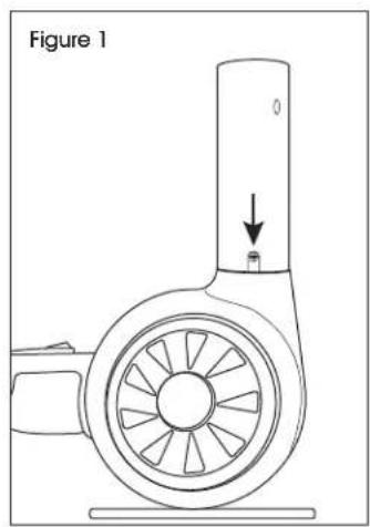
- Use a Phillips screwdriver to remove screws that hold outer nozzle shield in place. (See Figure 1)
- Remove outer nozzle shield, then inner nozzle shield. (See Figure 2)

NOTE: The inner nozzle shield is tightly connected to gun body. Wiggle back and forth to help remove.
natural_image
Technical line drawing of a mechanical fan or pump component with a downward arrow indicating motion (no text or symbols)
natural_image
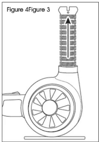
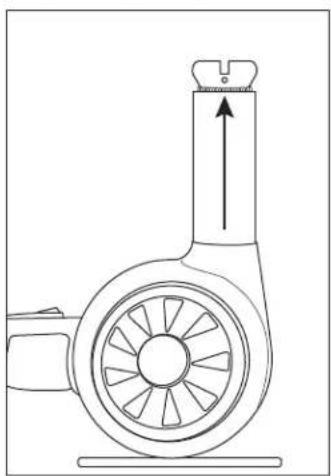
Technical line drawing of a mechanical fan or pump component with directional arrow (no text or symbols)- Remove the mica sleeve from around heating element. (See Figure 3)
- Remove heating element by pulling straight out. (See Figure 4)
natural_image
Technical line drawing of a mechanical component with a central shaft and fan-like structure (no text or symbols)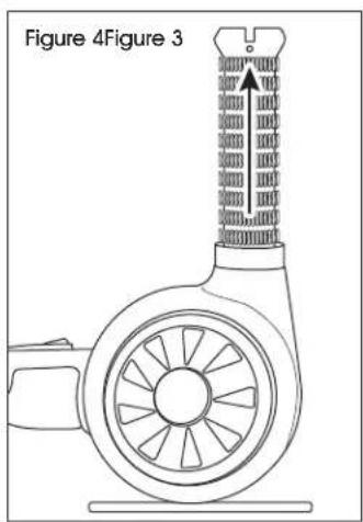
text_image
Figure 4Figure 3- Using pliers, squeeze heating element sockets slightly to ensure a tight connection with new heating element prongs. (See Figure 5)
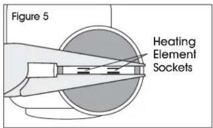
text_image
Figure 5 Heating Element SocketsHEATING ELEMENT REPLACEMENT CONTINUED
- Insert new heating element by snapping prongs into sockets. (See Figure 6)
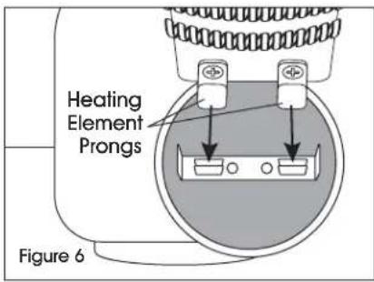
text_image
Heating Element Prongs Figure 6- Replace mica sleeve around new element. (See Figure 7)
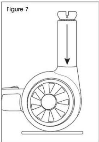
natural_image
Technical line drawing of a mechanical component with a downward arrow indicating motion or force (no text or symbols)- Cover with inner nozzle shield, ensuring edges of heating element align with anchors inside of inner nozzle shield. (See Figure 8)
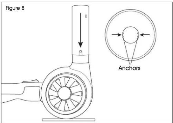
text_image
Figure 8 Anchors- Align openings on either side of inner nozzle shield with screw holes in the body of the gun.
- Replace outer nozzle shield. (See Figure 9)
- Replace screws. (See Figure 9)

natural_image
Technical line drawing of a mechanical component with a labeled arrow and scale indicator (no text or symbols beyond label)ULINE
H-8094
natural_image
Line drawing of a hair dryer with a circular fan and handle (no text or symbols)natural_image
Technical line drawing of a mechanical component with a central shaft and fan-like structure (no text or symbols)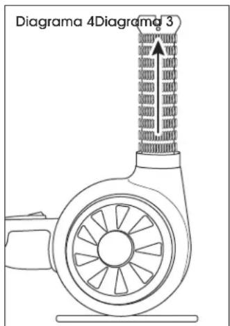
text_image
Diagrama 4Diagrama 3natural_image
Two types of screwdrivers shown side by side: a standard screwdriver and a pair of standard pliers (no text or symbols present)natural_image
Line drawing of a hair dryer with a circular fan and handle (no text or symbols)CONSIGNES DE SÉCURITÉ

natural_image
Technical line drawing of a mechanical fan or pump assembly with a downward arrow indicating motion (no text or symbols)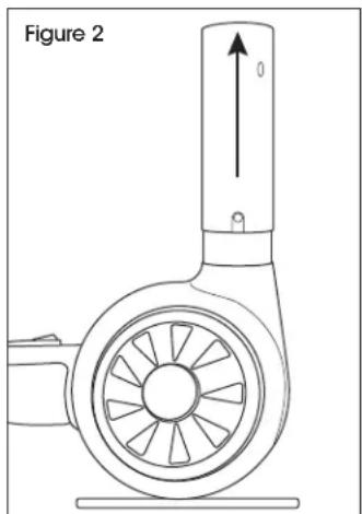
natural_image
Technical line drawing of a mechanical component with a circular base and radial blades, labeled 'Figure 2' (no text or symbols on the diagram itself)natural_image
Technical line drawing of a mechanical device with a central shaft and fan-like components (no text or symbols)