
Molda 5.0f - Milling machine SCHEPPACH - Free user manual and instructions
Find the device manual for free Molda 5.0f SCHEPPACH in PDF.

| Product Type | Benchtop Wood Milling Machine |
| Brand | Scheppach |
| Model | Molda 5.0f |
| Power Supply | 220-240 V / 50 Hz (single-phase) or 380-420 V / 50 Hz (three-phase) |
| Rated Power Consumption P1 | 2.8 kW |
| Output Power P2 | 2.0 kW |
| Motor Speed | 2800 rpm |
| Spindle Speeds | 1800 / 3000 / 6000 / 9000 rpm (4 mechanical speeds) |
| Operating Mode | S6 40% (periodic continuous duty) |
| Table Dimensions | 1000 x 600 mm |
| Overall Dimensions (L x W x H) | 1000 x 730 x 1230 mm |
| Table Height | 920 mm |
| Net / Gross Weight | 220 kg / 250 kg |
| Spindle Diameter | 30 mm |
| Spindle Height Adjustment Range | 100 mm |
| Spindle Tilt | -5° to +45° |
| Maximum Tool Diameter | 185 mm |
| Table Insert Rings Supplied | ∅115, 155 and 200 mm |
| Dust Extraction Connection | ∅100 mm, flow rate 565 m³/h |
| Sound Power Level (machining) | L_WA = 99.7 dB(A) |
| Safety | Motor brake (stop in 10 s), motor access door lock, protective devices and push sticks included |
| Delivery Content | Protective guide, milling fence with push sticks, thickness rings, keys, extraction sleeve, technical manual |
| Warranty | Legal (defective parts replaced free of charge) |
Frequently Asked Questions - Molda 5.0f SCHEPPACH
User questions about Molda 5.0f SCHEPPACH
0 question about this device. Answer the ones you know or ask your own.
Ask a new question about this device
Download the instructions for your Milling machine in PDF format for free! Find your manual Molda 5.0f - SCHEPPACH and take your electronic device back in hand. On this page are published all the documents necessary for the use of your device. Molda 5.0f by SCHEPPACH.
USER MANUAL Molda 5.0f SCHEPPACH

Tischfräsmaschine
Translation from original manual
Toupie
natural_image
Technical line drawing of a mechanical machine assembly (no text or symbols visible)Hersteller:
Günzburger Straße 69
natural_image
Blue circular sign with white safety helmet and mask icon (no text)[mm] 2x 15, 4x 10, 4x 5, 4x 0,5
[1/min] 1800/3000/6000/9000
[mm] 200
[mm] 75/115; 105/155; 145/200
natural_image
Close-up of a hand holding a screwdriver inserted into a small mechanical component (no text or symbols visible)natural_image
Green mechanical device with labeled parts, showing a cutting tool and base plate (no text or symbols visible)Abb.: „C“
natural_image
Close-up of a mechanical device with a paper strip attached, no visible text or symbolsAbb.: „D“
Abb.: „D“
natural_image
Close-up of a mechanical assembly with metal components and bolts, no visible text or symbolsnatural_image
Technical line drawing of a mechanical clamp assembly with a wrench and spring (no text or symbols)Fräsanschlag
Abb."H"
Abb."J"

Dokumentation
Abb."K"
Schleifarbeiten
natural_image
Technical line drawing of a mechanical component with threaded ports and mounting base (no text or symbols)Drehzahleinstellung
Abb. "L"
natural_image
Close-up of a green mechanical device with labeled components and transparent base (no readable text or symbols)natural_image
Green laboratory instrument with labeled component '6' and transparent housing (no readable text or symbols)natural_image
Industrial machine with layered material and labeled components (no readable text or symbols)Richtiges Rüsten

natural_image
Person using a green mechanical device to adjust or install a blue liquid in a circular chamber (no visible text or symbols)natural_image
Close-up of a mechanical assembly with green and black components, no visible text or symbolsnatural_image
Person operating a green cutting machine on a wooden cutting board in a workshop (no visible text or symbols)natural_image
Line drawing of two wooden beams or supports, one with a U-shaped groove and the other flat (no text or symbols)natural_image
Simple line drawing of a wooden beam joint with a flat support (no text or symbols)halbe Nutung
natural_image
Technical line drawing of a wooden plank and support structure (no text or symbols)natural_image
Simple line drawing of a wooden L-shaped bracket with visible grain texture (no text or symbols)halbe Überblattung
natural_image
Simple line drawing of a wooden plank with visible grain and texture (no text or symbols)ganze Nutzung
natural_image
Line drawing of a wooden beam joint (no text or symbols)natural_image
Simple line drawing of a wooden L-shaped bracket with visible grain texture (no text or symbols)natural_image
Technical line drawing of a wooden beam joint with visible grain and fasteners (no text or symbols)natural_image
Technical line drawing of a wooden joint or bracket assembly (no text or symbols)Überblattung
natural_image
Technical line drawing of wooden joint fasteners (no text or symbols)natural_image
Technical line drawing of wooden joint fasteners (no text or symbols)natural_image
Simple line drawing of two wooden beams with connectors, no text or symbols presentnatural_image
Technical line drawing of two mechanical components: a wooden bracket and a vertical wooden bracket (no text or symbols)natural_image
Illustration of wooden door and shelf, showing a side profile and a close-up of the shelf (no text or symbols)einfacher Zapfen
natural_image
Technical line drawing of a wooden post with two clamps (no text or symbols)Blatt und Zapfen
Wartung

Spindle Moulder
Manufacturer:
Günzburger Straße 69
We wish you a pleasant and successful working experience with your new spindle moulder.
NOTE:
In accordance with the applicable product liability law, the manufacturer of this machine is not liable for damage which arises on or in connection with this machine in case of:
⇒ Improper handling
→ Non-compliance with the operating instructions
⇒ Repairs by third-party, non-authorised technicians
→ Installation and replacement of “non-original spare parts”
→ Non-compliance with the "intended use"
⇒ Outages of the electrical system due to non-compliance with the electrical specifications and VDE regulations EN 60204-1
Recommendations:
Read the entire text of the operating instructions prior to assembly and operation of the machine.
These operating instructions are intended to familiarise you with the machine and help you utilise it for its intended purpose.
The operating instructions contain important notes on how to work safely, correctly and economically with your machine and how to avoid dangers, save on repair costs, reduce downtime and increase the reliability and working life of the machine.
In addition to the safety regulations contained within the operating instructions, you must ensure that you comply with the applicable regulations of your country with respect to the operation of the machine.
Put the operating instructions in a clear plastic folder to protect them from dirt and humidity and store them near the machine. The instructions must be read by each operator prior to starting work and closely complied with. Only persons who have been trained in the use of the machine and have been instructed about the related dangers and risks are allowed to use the machine. The required minimum age must be met.
In addition to the safety notes contained in these operating instructions and the special regulations of your country, the generally recognized technical rules for the operation of wood-working machines must be observed.
Contents
GENERAL NOTES 33
PROPER USE 34
RESIDUAL RISKS 35
SCOPE OF DELIVERY 35
SPECIFICATIONS 36
INSTALLATION AND ADJUSTMENT 39
OVERHEAD ROLLER GUARD ASSEMBLY (SUPPLIED AS STANDARD) 39
CURVED MOULDING GUARD (STANDARD) 39
ELECTRICAL CONNECTION 40
FORWARD AND REVERSE DRIVE SWITCH 41
CONNECTION DIAGRAM FOR 380-420V / 50Hz 43
CONNECTION DIAGRAM FOR 220-240V / 50Hz 44
OPERATION 45
SPEED SETTING 47
TIPS FOR WORKING 49
CORRECT SET-UP 50
DIFFERENT APPLICATIONS FOR THE SPINDLE MOULDER 51
MAINTENANCE 55
TENSIONING THE BELT 55
TROUBLESHOOTING 56
ACCESSORIES: 56
EC DECLARATION OF CONFORMITY 57
WARRANTY 57
General notes
When you unpack the machine, check all parts for possible transport damage. Inform the supplier immediately in case of complaints.
→ Complaints received at a later date will not be recognised.
→ Check that the delivery is complete.
Only use original Scheppach parts for accessories and for worn and spare parts. Spare parts are available from your specialist dealer.
Specify our part numbers and the type and year of construction of the machine in your orders.
→ This symbol indicates safety-related information in these operating instructions.

Check the mains connecting cables. Do not use defective cables. See "Electrical connection".
→ Keep away children from the machine when it is connected to the mains.
⇒ The operator must be at least 18 years old. Trainees must be at least 16 years old, but may only use the machine under supervision.
Do not distract the attention of persons operating the machine.
Keep the operator's area free from chips and waste wood.
Do not wear loose clothing. Remove jewellery, rings and wristwatches.
→ Installation, repair and maintenance work relating to the electric installation may only be performed by qualified specialists.
⇒ Turn off the machine before you repair malfunctions. Disconnect the mains plug.
→ Use a suction device to remove wood shavings and sawdust.
⇒ Turn off the motor when you leave the workplace. Disconnect the mains plug.
Disconnect the machine from the external energy supply, even when moving it only a short distance! Properly reconnect the machine to the mains before you turn it on again!
⇒ The machine should be disposed of in accordance with relevant local regulations.
→ Operator training
Read the operating instructions to familiarise yourself with the machine prior to using it.
→ Circulate the safety instructions to all persons working with the machine.
Observe all safety instructions and warnings on the machine.
⇒ Make sure that all safety instructions and warnings on the machine are always in a readable state.
⇒ Be careful when working with the machine – the rotating cutting tool may cause injury to fingers and hands.
Stability: Make sure the machine is installed on firm ground with sufficient stability.
→ Set-up and adjustment of the machine
→ Only work with sharpened cutting tools.
→ Use the insert rings to adjust the table opening to the tool diameter.
→ Immediately replace defective tools (if cracked etc.). See the section on replacing tools!
→ Only use tools that comply with the European standard EN 847-1.
→ Only use authorised manual-feed tools.
Observe the tool manufacturer's recommendations when clamping the tool.
Only perform retooling, measuring and cleaning work when the motor is turned off. Disconnect the mains plug and wait until the rotating tool comes to a halt.
When undertaking moulding tasks, always ensure that the tool is protected by the prescribed safety devices.
→ Remove the insert ring from the table plate before inserting the facing cutter.
Workpiece guidance
→ Use devices for safe workpiece guidance for all moulding tasks.
→ Use a sliding stick to support manual feed or use a power feed device (accessory).
In the case of shorter workpieces, bridge the opening between the fence halves to enable constant workpiece guidance.
When tooling longer workpieces, use the Scheppach table extension or sliding table carriage (accessory).
→ Rotation direction and speed selection
Rotation direction
→ Down milling is not a permissible procedure.
Do not start work until full speed has been reached.
Pay attention to the direction of rotation of the motor and the tools. See "Electrical connection".
→ Speed selection
⇒ The maximum speed specified on the moulding tool used should not be exceeded/ under run. Select the appropriate speed in accordance with the speed chart on the machine.
→ Maximum spindle speed: 8500 rpm
⇒ Machine operation, selection and adjustment of separating safety devices
⇒ The safety devices on the machine must not be dismantled or rendered unusable.
When working on the machine, all safety devices and covers for the relevant moulding procedure must be in place.
All protection and safety devices must be immediately reinstalled once the repair and maintenance work is completed.
Moulding at the fence where the workpiece is being tooled along its full length
Moulding the long side and front side
Use the moulding fence, overhead roller guard assembly or the power feed device (accessory).
→ Curved moulding
→ Used the curved moulding fence for curved moulding tasks.
→ Insert moulding
→ Use the moulding fence and overhead roller guard assembly.
→ Use the table extension with the cross stop.
→ You are recommended to use a holding device for smaller workpieces.
→ Tenon cutting and grooves
During grooving and tenon work, a sliding table carriage with groove cutter guard, clamping device and moulding fence with cover should be used for workpiece guidance.

Proper use
⇒ The spindle moulder is built to be used exclusively with the supplied tools and accessories for wood working.
The machine meets the currently valid EU machine directive.
⇒ The machine has been designed for a one-shift operation, operating factor S6 – 40%.
→ Observe all safety instructions and warnings on the machine.
⇒ Make sure that all safety instructions and warnings on the machine are always in a readable state.
A suction device with a flexible, non-flammable suction pipe should be connected before operating the machine.
⇒ The automatic switch-on is available as an accessory.
Type ALV 2, article no. 79104010 230V /50Hz
Type ALV 10, article no. 79104020 400V /230 /50Hz
When the machine is switched on, the suction system starts automatically after a delay of 2-3 seconds. This prevents the main fuse from being overloaded.
When the machine is switched off, the suction system continues to run for 3-4 seconds before it is turned off automatically.
⇒ Any remaining dust is extracted, as provided for by the Hazardous Substances Ordinance. This saves electricity and reduces noise. The suction device only runs when the machine is in operation.
A deduster must be used if the machine is operated for commercial purposes.
Do not switch off or remove suction devices or dedusters when the machine is in operation.
→ Only one person may work at the machine at any one time.
Only use the machine if it is in a technically fully functional state. Pay attention to the intended use, safety and potential dangers and comply with the operating instructions! Immediately repair any malfunctions that may affect safety, or have them repaired.
⇒ The safety, working and maintenance instructions and the dimensions stipulated in the specifications must be observed.
⇒ The applicable regulations for the prevention of accidents and other generally recognized safety rules must be observed.
The machine may only be used, maintained or repaired by trained persons who are familiar with the machine and have been instructed about the dangers. The manufacturer shall not be liable for any damage resulting from unauthorized modifications of the machine.
⇒ The machine may only be used with original accessories of the manufacturer.
Any other use is considered to be not intended. The manufacturer shall not be liable for any damages that may result from such use. Such risk is borne exclusively by the user.
Residual risks
The machine has been constructed according to current technical standards and recognised safety rules. Nevertheless, single residual risks may occur during operation.
⇒ The rotating cutting tool may cause injury to fingers and hands if the workpiece is not guided in the proper manner.
⇒ Injury may be caused by a spinning workpiece if you work using inadequate support or guidance, for instance by working without a fence.
→ Danger to health from sawdust or wood shavings.
⇒ Always wear personal protection equipment as well as goggles and a dust mask. Use the suction device!
⇒ Health hazard from excessive noise. The permissible noise level is exceeded when working with the machine. Always wear personal protection equipment such as ear protection.
→ Danger from electric current if incorrect electrical connecting cables are used.
⇒ Only machine selected wood without flaws such as: knots, lateral cracks, surface cracks.
⇒ Wood that contains flaws can pose a risk when worked.
⇒ Risk of injury from defective cutting tools. Check the tools regularly to ensure they are intact.
Additionally, non-obvious residual risks may exist in spite of all measures taken.
Residual risks can be minimised by carefully observing the "Safety instructions" and the "Intended use" as well as the entire operating instructions.
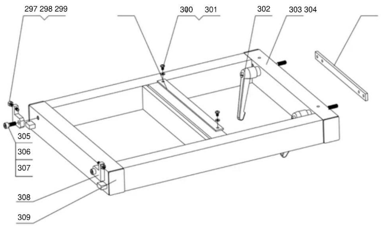
Scope of delivery
Molda 5.0f Spindle Moulder
Curved moulding guard complete
with suction connector
Moulding fence complete with
overhead roller guard assembly
Spindle bushing, 2 pcs 0,5mm long
Spindle bushing, 2 pc. 5 mm long
Spindle bushings, 2 pc. 10 mm long
Spindle bushing, 1 pc. 15 mm long
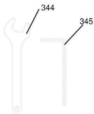
Single-head wrenches, 1pc. SW 41
Allen key SW10
Suction connector
Accessory bag
Operating instructions
Accessories: page 28
Article no. 7231 0019
Article no. 7210 5000
Article no. 3301429011
Article no. 3301429010
Article no. 3301429009
Article no. 3301429008
Article no. 0108 9413
Article no.
Article no. 7500 3800
Specifications
| Drive: | |||
| Machine article no. | 7231 0903 | 7231 0904 | |
| Electric motor | [V] | 220-240/50Hz | 380-420/50Hz |
| Input P1 | [kW] | 2,8 | 2,8 |
| Output P2 | [kW] | 2,09 | 2,2 |
| Motor speed | [rpm] | 2762 | 2820 |
| Operating mode S6/40% | S6/40% | ||
| Current rating | [A] | 12.2 | 7,7 |
| Weight gross/net | [kg] | 220 | 220 |
| Suction system: | |||
| Suction connector ∅ | [mm] | 100 | |
| Flow speed | [m/s] | 20 | |
| Vacuum at suction connector | [Pa] | 350 | |
| Flow rate | [m3/h] | 565 | |
Working area: 1800 x 1150
Structural dimensions:
Overall length [mm] 1000
Overall width [mm] 600
Overall height [mm] 1230
Table height [mm] 930
Table length [mm] 1000
Table width [mm] 600
Table opening max. ∅ [mm] 185
Moulding spindle:
Spindle ∅ [mm] 30
Spindle bushings ∅ [mm] 50
Spindle bushing height [mm] 2x 15, 4x 10, 4x 5, 4x 0,5
Height-adjustable area [mm] 100
Spindle speed [rpm] 1800/3000/6000/9000
Tool max. ∅ [mm] 200
Insert ring ∅ [mm] 75/115; 105/155; 145/200
Dimensions of machinable workpieces:
Min. dimensions W/H [mm] 8x8
Max. dimensions H [mm] 120
Operating conditions:
Temperature [°C] +5 to +40
Humidity (non-condensing) [%] 30 to 95
Storage conditions:
Temperature [°C] -20 to +55
Humidity (non-condensing) [%] 30 to 95
! Subject to technical modifications!
Noise parameters
The noise emission values determined in accordance with DIN EN ISO 3746 for the sound power level and EN ISO 11202 for the sound pressure level at the workplace are based on the working conditions listed in Appendix A of ISO 7904.
| Sound power level in dB |
| Idle running L_WA = 96,4 dB(A) – Operation L_WA = 99,7 dB(A) |
| Sound pressure level at the workplace in dB |
| Idle running L_pAeq = 80,5 dB(A) – Operation L_pAeq = 83,7 dB(A) |
A uncertainty allowance of K=4dB is made for the emission values listed
Note
The values specified here are emission values and do not therefore necessarily represent definite workplace values. As there is no correlation between emission values and workplace values, they cannot be reliably used to determine whether any further precautions need to be implemented. Factors that may influence the current workplace value include the duration of exposure, the nature of the workroom, other noise sources, the number of machines and other related influences. The reliable workplace values may also vary from place to place. This information is intended to enable users to make a better assessment of danger and risk.
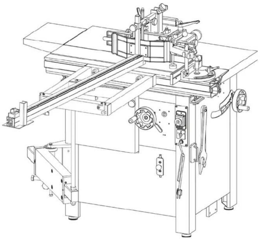
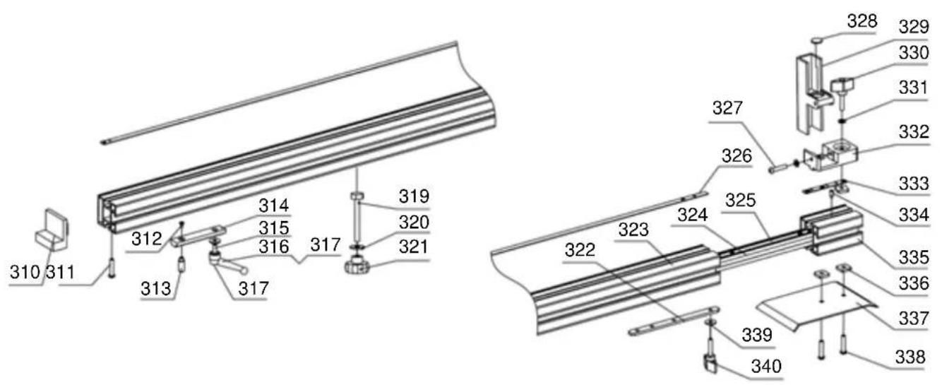
Installation and adjustment
Height compensation
Figure A
The machine is supported by four adjustable rubber feet.
Compensating for uneven floors: undo the lower hexagonal nuts using a spanner and screw the rubber feet in or out as required.
Retighten the hexagonal nuts.
Caution!
Use a spirit level to align the machine.
If the rubber feet are removed, the machine can be screwed to the floor via the threaded drill holes.
Figure A
natural_image
Close-up of a hand holding a screwdriver next to a small mechanical component (no visible text or symbols)Overhead roller guard assembly (supplied as standard)
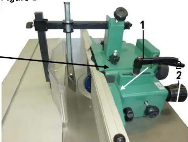
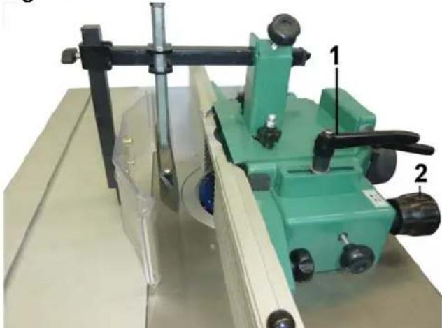
Figure B
⇒ Mount the overhead roller guard assembly at right angles to the table plate using two knurled screws and discs (1).
Use the set screw (2) to adjust the overhead roller guard assembly.
Figure B
natural_image
Mechanical device with green frame and labeled parts (1, 2), no visible text or symbols on the main subjectFigure C
Curved moulding guard (optional)
Bearing ring
Affix the curved moulding guard to the table plate using two knurled screws and discs.
The bonded wood guide rail can be mounted on the moulding table on both sides at a tangent to the bearing ring. (M 8 x 45 hexagonal nut and disk ∅ 8)
Figure C
natural_image
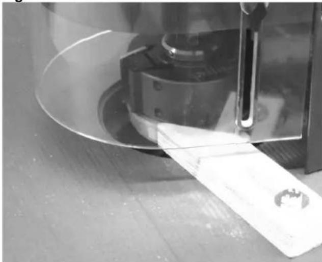
Close-up of a mechanical component with a paper strip and tool, no visible text or symbolsFigure D
Figure D
Mounting the complete curved moulding fence to the machine table:
Supplementary set for curved moulding fence (optional)
- First affix the adjustment device for the curved moulding fence to the guard.
- Then affix this unit to the table plate using three hexagonal screws and discs.
Curved fence plates
⇒ The R 90 curved fence plate is fitted.
⇒ The R 60 curved fence plate may have to be fitted instead of the R 90 as required.
natural_image
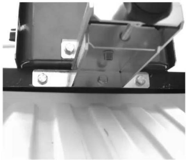
Close-up of a mechanical assembly with metal components and bolts, no visible text or symbolsElectrical connection
When operating for the first time, th
Figure E

Connect the machine to the mains supply using the CEE plug. The supply cable must be fused with 16A.
The standard rotation direction is left (counter clockwise). The rotation direction selection switch should be set to "forward". If not, the polarity should be switched using a screwdriver. See Figure E. The rotation direction needs to be rechecked whenever the mains connection and machine location is changed.
Forward and reverse drive switch
⇒ The rotation direction switch can be used to switch the spindle to reverse drive.
To turn the rotation direction to "reverse", the press and turn the safety button to the right. In reverse mode (clockwise), the control lamp lights up.
→ The speed display lamps indicate the speed currently set.
→ Press the green button on the operating switch and the moulding spindle starts up.
⇒ The power feed device can be connected to the additional socket.
⇒ Press the red button to switch off. The moulding spindle will come to a halt within 10 seconds.
In an emergency, the red knob (EMERGENCY STOP) can be used to turn off the machine. This also brings the moulding spindle to a halt within 10 seconds.
Figure F
For safety reasons, it is not possible to switch the rotation direction when the motor is running. The motor needs to be switched back on whenever the direction is switched.
If the reverse direction is chosen, the working direction changes from left to right. The moulding tool needs to be mounted revolved through 180°.
The installed electric motor is connected and is ready to work. The connection complies with the relevant VDE and DIN regulations. The connection to the mains supply on the customer side and the extension cable used must meet these regulations or the provisions of the local power supply company.
Motor brake
If the machine is switched off, an automatically operated counter-current brake ensures secure braking. The brake reduces the speed of the machine's drive motor within 10 seconds. The electrical braking is interrupted after a maximum of 10 seconds. If the braking operation takes longer than 10 seconds, the machine must no longer be operated as the brake is defective. The machine must be disconnected from the power supply. Only qualified electricians may undertake troubleshooting.
Operating mode/operating time
The electric motor has been dimensioned for the S6 - 40% operating mode.
S6 = Continuous operation duty type
40% = refers to 10 min - 4 min. operation; 6 min. idle running.
If the motor is overloaded, it automatically switches off due to the winding thermostat inserted in the motor winding. After a (variable) cooling period, the motor can be turned on again.

Defective electrical connection cables
Insulation damage can often occur on electrical connection cables.
Possible causes are:
⇒ Pressure points if connection cables have been run through window or door openings.
Kinks due to improper attachment or routing of the connection cable.
→ Cuts caused by running over the connection cable.
→ Insulation damage caused by pulling the connection cable out of the wall socket.
⇒ Cracks caused by the aging of the insulation. Such defective electrical connection cables must not be used and the insulation damage means they pose danger of death!
Regularly check the electrical connection cables for damage. Please make sure that the connection cables are disconnected from the mains supply during the check. Electrical connection cables must meet the applicable VDE and DIN regulations and the provisions of the local power supply company. Only use connection cables labelled with H 07 RN. Labelling of the connection cable with the type specification is mandatory.
Extension cables up to a length of 25m must have a cross section of 1.5mm^2 , and cables with a length exceeding 25m must have a minimum cross section of 2.5mm^2 .
⇒ The mains connection is protected with a 16A delay-action fuse.
Three-phase current motor
→ The supply voltage must be 380-420V 50Hz.
⇒ The connection to the mains supply and the extension cables must be of a five-core type (3 P + N + SL).
⇒ The extension cables must have a minimum cross section of 1.5 mm ^4 .
⇒ The mains connection should be fused with a maximum of 16A.
⇒ The rotation direction needs to be rechecked whenever the mains connection and machine location is changed. The polarity may also have to be switched.

Connections and repairs to the electrical equipment may only be performed by a qualified electrician. If you have further questions, please specify the following:
→ Motor manufacturer and type
→ Motor current type
⇒ Data from the machine type plate
→ Data of the electric control
If you return the motor, always return the complete drive unit with the electrical control.
Connection diagram for 380-420V / 50Hz
Connection diagram for 220-240V / 50Hz
peration
All protection and safety devices must be installed.
Only perform retooling, measuring and cleaning work when the motor is turned off. Wait until the rotating tool comes to a halt before disconnecting the mains plug.
Moulding tool and insert ring
Figure G
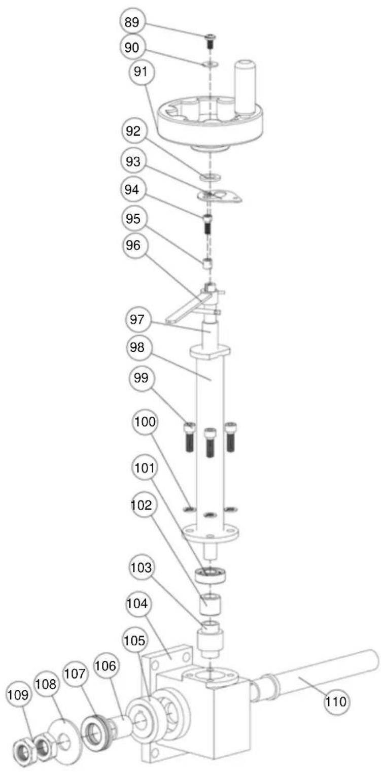
Note the application of the various moulding tools. Insert the corresponding insert ring (∅115mm or Insert ring ∅65mm: 7231 0739. The Insert ring must be used when working withmoulding tool greater than 110 mm. Observe the rotation direction of the moulding tool! Place the moulding tool and the spindle bushings on the moulding spindle and secure them using the safety disc and M 18x1.5 hexagonal nut. Firmly tighten the spindle nut. (SW 41 single-head wrench)
Caution! Always insert the moulding tool in the lower position.
FigureG
natural_image
Technical line drawing of a mechanical assembly with a wrench, spring, and screw (no text or symbols)oulding fence
Figure H
Undo the two handles (1a) and align the fence guard parallel to the front edge of the table.
(2) Fine adjustment of the moulding depth
Tighten the handles (1a), ensuring that the parallel alignment of the moulding fence to the workpiece is not altered.
Undo both handles (2a) and perform the fine adjustment on handle (2). One scale mark on the handle corresponds to 0.1mm.
Retighten the handles (2a) to their working position.
(3) Setting the fence profile
Undo the two handles (3) and set the two fence profiles in accordance with the tool.
Align the fence profiles as closely to the moulding tool as possible and tighten the handles.
A positioning pin in each of the fence profiles prevents unintended removal of the fence profiles. Unscrew the handles to replace the fence profiles.
Figure H
Curved moulding fence
Inserting the curved fence plates
Moulding tool ∅
Curved fence plate
∅100-120mm
R 60mm
Up to ∅140mm
R 90mm
The correct setting of the curved fence depends on the diameter of the moulding tool and the thickness of the respective workpiece and the desired moulding depth.
Figure I
Settings
As a general rule, the moulding tool should be in the lower position whenever possible. The curved fence plate is positioned above it.
- Set the moulding tool to the working height.
- Set the curved fence plate (R60 or R90) in accordance with the workpiece thickness and working depth.
- Lower the guard plate to 2mm above the workpiece.
- Align the brushes on both sides of the workpiece so that moulding shavings are brushed away during work.
Figure J
External radii
To mould external radii, guide the workpiece along the curved fence plate. The optimum moulding depth is achieved in position 3 (X).
Illustrations with Supplementary set: 7231 1746 (Accessories)
Figure I
Figure J

Figure K Sanding tasks
For sanding operations tasks with the drum sanding attachments (accessory, article no. 7930 3500 or 7930 3000), the curved moulding guard (supplied as standard) is used as a cover. The curved moulding fence plate is not required and should be removed.
Figure K
natural_image
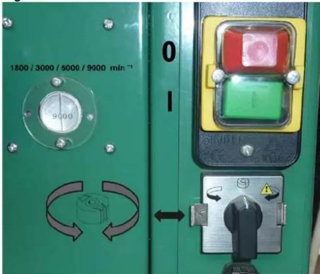
Technical line drawing of a mechanical device with multiple adjustment knobs and a central cylindrical component (no text or symbols)Speed setting
Figure L
Note the maximum rotation speed specified on the moulding tool and the sticker on the side of the switch: "Optimum speed range for moulding tools on spindle moulders."
Your spindle moulder is equipped with the speeds 3000/6000/8200 rpm.
- Open the cover on the rear side.
The electrical circuit to the motor is interrupted when the cover is opened
- Undo the belt tensioning device
The belt is detensioned
- Select speed
Undo the ball knob screw, set the required speed, the corresponding display lamp (3000/6000/8200) lights up on the switch housing. Tighten the ball knob screw.
- Move the belt
- Clamp the belt-tensioning device and close the cover as per the regulations to remove the electrical motor lock.
Figure L
Speed chart
Maximum speed depending on the moulding tool diameter or moulding thickness
| Mot. speed | ∅ 200 | ∅ 180 | ∅ 160 | ∅ 140 | ∅ 120 | ∅ 100 | Moulder ∅ |
| 9.000 | 14 | 18 | 30 | 50 | 100 | 120 | Moulding thickness / cutting width [mm] |
| 6.000 | 28 | 45 | 70 | 120 | 120 | 120 | |
| 3.000 | 120 | 120 | 120 | 120 | 120 | 120 | |
| 1.800 | 120 | 120 | 120 | 120 | 120 | 120 |
9000 rpm
6000 rpm
3000 rpm
1800 rpm
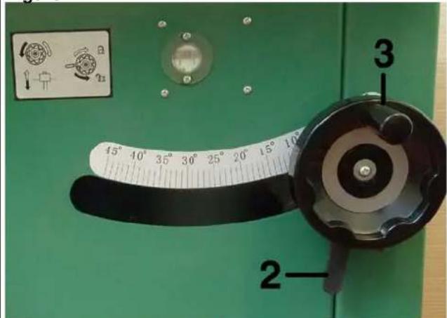
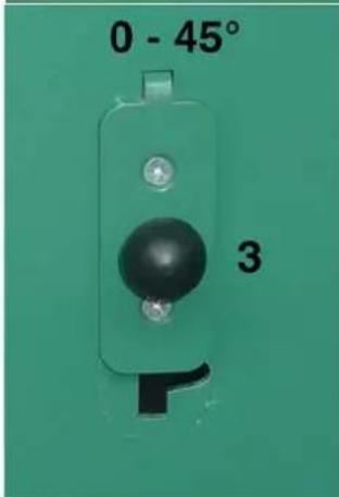
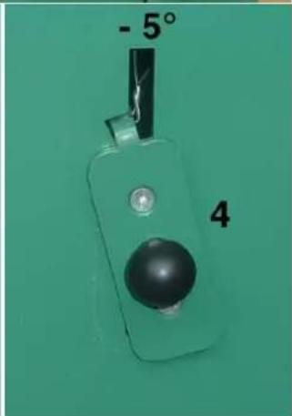
Moulding spindle adjustment
Figure M

!! Caution!
The moulding spindle should only be adjusted when the motor is switched off and the moulding tool is at a standstill!
Spindle height adjustment: 95mm
- T he handwheel (1) is used to adjust the height.
- D isengage the spindle brake at the clampi ng handle (2) and adjust the height using the handwheel.
- O ne scale mark on the scale plate corresponds to 0.1mm. One turn of the handwheel corresponds to 2mm.
- W hen the tool height has been successfully adjusted, firmly tighten the clamping handle.
Always perform a test moulding and remeasure the workpiece!
Figure M
Note
Figure N
- T he machine door on the front side must be closed as per the regulations for the machine to be operated.
- C onnect the main cable
- T urn the direction switch to "left or right".
- S witch on the motor switch using the green button of the operating switch.
- T o switch the machine off normally, use the red button of the operating switch.
- T he "emergency stop" can be used to stop the machine in an emergency.
Figure N
Tips for working
Only perform retooling, measuring and cleaning work when the motor is turned off and the moulding tool is at a standstill. Secure the machine from being switched on unintentionally!
Disconnect the mains plug!
Workpiece guidance, figure O
The feed direction of the workpiece always depends on the motor direction.
When the motor direction is “forwards”, the workpiece feed direction is “right” to “left”. When the motor direction is “reverse”, the workpiece feed direction is “left” to “right”.
(1) Workpiece feed direction
- Pay attention to the workpiece guidance. Use aids such as push handles (accessory, article no. 7963 1000) for small workpieces.
- The table extension no.7324 0170 (accessory) should be affixed for long workpieces.
(2) Workpiece – pushing from above
- Use the push shoe to push the workpiece on to the table plate from above.
(3) Workpiece – pushing from the side
- As well as applying pressure from above, push the workpiece against the moulding fence from the side.
- Place the push plate at the side of the workpiece.
- Adjust guard "A" to the workpiece height.
(4) Moulding tool – direction
- The feed direction of the workpiece (1) always depends on the motor direction (4).
- The rotation direction can be changed from "forward" to "reverse" for specific tasks using the reversing switch.
Overhead roller guard assembly, figure P
natural_image
Green mechanical device with labeled components and transparent base, no visible text or symbolsLoosen the two clamp screws (5) by a maximum of two turns and pull them back with the clamp flaps.
Figure O
Safety distance when using the power feed device
When using the power feed device, the distance from the last feed roller and the wall should be at least 55cm longer than the workpiece.
natural_image
Green laboratory instrument with labeled parts, no visible text or symbolsThe entire overhead roller guard assembly can now be folded upwards
Figure Q
Inserting the guide rail
The guide rail is inserted into the moulding fence at the right height to safely bridge the moulding fence distance when working with short workpieces. The guide rail is clamped by pushing the two aluminium fence profiles together.
natural_image
Industrial machine with layered material and labeled components (no readable text or symbols)Correct set-up

The requirement for working safely!
- Select the moulding tool and appropriate insert ring.
- Check the moulding tool. Replace damaged moulding blades. Select the speed in accordance with the moulding tool and required procedure. Note the "Optimum speed range for moulding tools on spindle moulders" sticker on your machine.
- Set the working height and depth and the incline of the moulding spindle with the motor turned off.
- Set the moulding fence and safety device in accordance with the required procedure.
- To ensure safe working, check the important securing screws of the moulding fence or the table extension and tighten if necessary.
- Perform a test moulding – never work without a safety device.
Replacing the moulding tool
Figure R
When replacing the moulding tool, pay attention to the insert ring. Depending on the moulding tool, the insert ring may have to be replaced or removed completely.
Caution!
Switch off the motor and disconnect the mains plug.
Replace the moulding tool!
Firmly tighten the spindle nut with the two SW 41 single-head wrenches.
- When changing the tool, only touch the moulding tool with gloves – danger of injury!
- Set the moulding tool and safety devices (see "Correct set-up" chapter)
- Reversing switch – selecting the rotation direction
- Switch the motor back on.
natural_image
Person using a green mechanical device to adjust or install a blue cylindrical component (no visible text or symbols)Different applications for the spindle moulder
Caution!
The correct insert ring must be used when inserting the moulding tools.
The following images are depicted with no protective devices for improved visibility.
Use the prescribed protective devices when working!
Moulding the long side
Figure S
Guide the workpiece along the moulding fence using the overhead roller guard assembly.
- Use the power feed device if possible (accessory: article no.: 6807 0000).
Safety note:
When using the power feed device, the distance from the last feed roller and the wall should be at least 55cm longer than the workpiece.
Moulding the front end
Figure T
Guide the workpiece along the moulding fence using the overhead roller guard assembly and the guide rails.
- With the sliding table can be used to machine a surface exactly perpendicular to the long side.
Insert moulding
Figure U
The moulding fence and the miter gauge with the clamping device should be used for insert moulding tasks.
Cover the moulding tool with the overhead roller guard assembly.
Place the workpiece at the anti-kickback device, swivel it inwards and feed it forwards.
Figure S
natural_image
Close-up of a hand pressing down on a wooden plank in a machine shop (no visible text or symbols)Figure T
natural_image
Person operating a green cutting machine on a wooden board, no visible text or symbolsFigure U
natural_image
Mechanical setup with green clamps and wooden components, no visible text or symbolsCorrosion protection: (accessory) article no.: 6100 9800
If the machine is not used for a period of time, the table surface should be sprayed with an anti-corrosion spray.
Application of various moulding tools
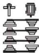
1 Rebating tasks with safety moulding head "A" – straight blade – various spindle bushings "B" for course setting. Tool aligned countersunk in table plate "C".
2 Safety moulding head "A" and same tool alignment as 1 when moulding a groove.
4 Safety moulding head "A" with profile cutters "E", spindle ring "D". Moulding cutter minimally countersunk in table plate.
5 Safety moulding head "A" with profile cutters "E" (countersunk in table plate). For moulding curved pieces with bearing ring "F" aligned in upper position
Caution! Only work with moulding guard "G" when moulding fence "H" has been removed.
6 Safety moulding head "A" with profile cutters "E" aligned in upper position and bearing ring "F" aligned in lower position for moulding curved pieces.
Caution! Only work with moulding guard "G" when moulding fence "H" has been removed.
7 Groove cutter "J" aligned in upper position with spindle bushings "B" and inlaid spindle ring "D" for moulding a groove.
8 Groove cutter "J" aligned in pairs with spindle bushings "B" and intermediate rings "K" for moulding a groove. Spindle ring "D" removed – lower groove cutter minimally inset into Table plate "C". Insert the groove cutters at 90° offset to each other.
9 Saw blade "L" for grooving or as initial operation for cutting a deep rebate. Spindle ring "D" inlaid.
10 As 9 but as second operation for groove cutting.
13 Facing cutter "N" aligned in upper position, spindle ring "D" removed.
Caution! Remove spindle ring before inserting the facing cutter.
14 Facing cutter "N" aligned in upper position – mounted revolved through 180°. Spindle ring "D" removed.
Caution! Pay attention to spindle direction. Set reversing switch to "reverse drive".
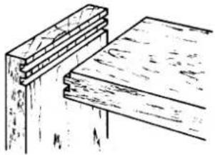
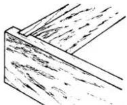
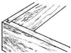
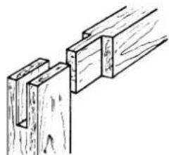
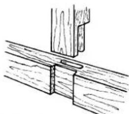
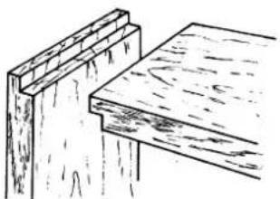
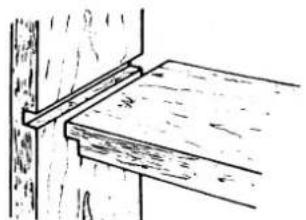
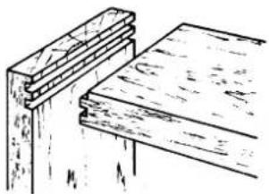
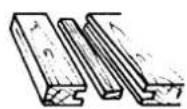
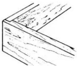
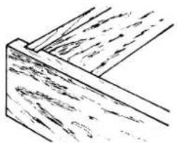
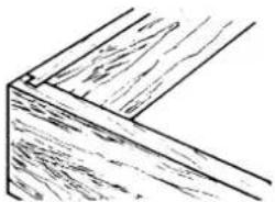
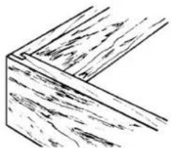
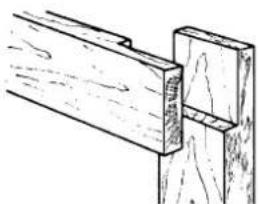
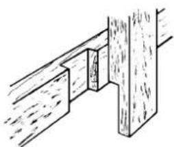
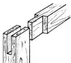
Wood joints
natural_image
Line drawing of two wooden beams or supports, one with a flat beam and the other with a flat beam (no text or symbols)One-sided covered rebate
natural_image
Simple line drawing of a wooden beam supported by a vertical rod (no text or symbols)Half notch
natural_image
Technical line drawing of a wooden plank and support structure (no text or symbols)Corner joint with two grooves
Notches with insert grooves
natural_image
Simple line drawing of a wooden L-shaped bracket with visible grain texture (no text or symbols)Half scarph
natural_image
Pure mechanical cross-section diagram without any text, numbers, or symbolsFull notch
natural_image
Line drawing of a wooden plank with visible grain and texture (no text or symbols)Opposite downward deflexion of tongue with moulded groove
natural_image
Line drawing of a wooden plank with visible grain texture (no text or symbols)Scarp with groove
natural_image
Technical line drawing of a wooden beam joint (no text or symbols)Single scarp
natural_image
Technical line drawing of a wooden beam joint with visible grain and wear (no text or symbols)Scarp
natural_image
Technical line drawing of wooden joint fasteners (no text or symbols)Mortise and tenon connection, single
natural_image
Technical line drawing of wooden joint fasteners (no text or symbols)Double mortise and tenon connection
natural_image
Simple line drawing of wooden beams and joints (no text or symbols)Scarp with rebate

natural_image
Technical line drawing of two mechanical components: a wooden bracket and a U-shaped bracket (no text or symbols)Double tenon with one-sided mitre joint
natural_image
Illustration of wooden door and shelf assembly (no text or symbols)Single tenon
natural_image
Technical line drawing of a wooden joint with a bracket (no text or symbols)Scarp and tenon
Maintenance
Only perform maintenance, repair and cleaning work when the motor is switched off.
Disconnect the mains plug!
All protection and safety devices must be immediately reinstalled once the repair and maintenance work is completed.
The machine tables should be kept free of resin. Contact your Scheppach dealer for Pharmol concentrated resin remover, article no. 6100 9700.
Occasionally clean and oil the regulating spindle of the height adjustment system, its bearings and drive shaft.
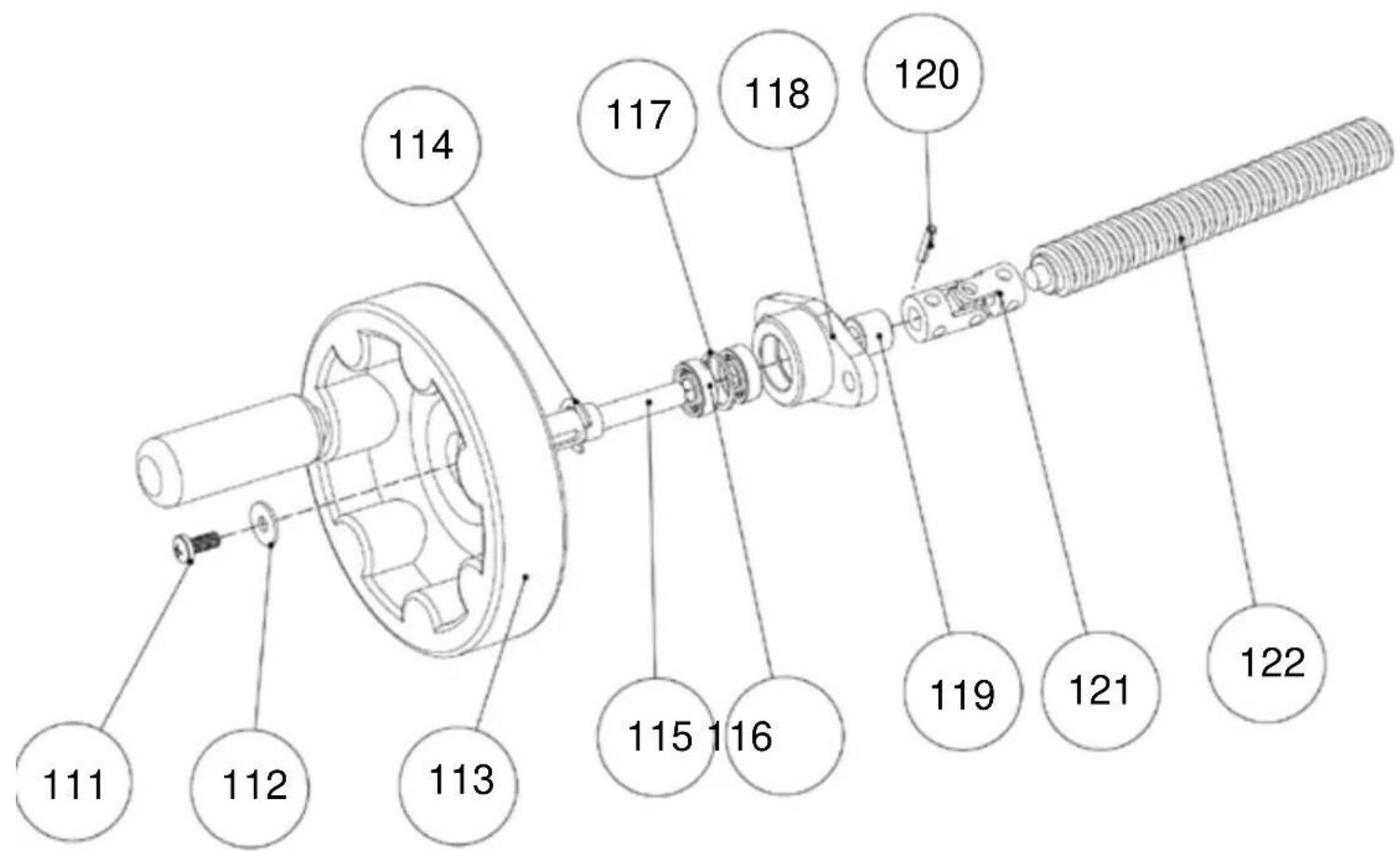
Tensioning the belt
Figure Z
- Open the front-side machine cover.
- Undo the belt-tensioning device.
- Remove the belt from the motor belt disc.
- Remove the upper safety disc from the joint bolt and remove the bolt.
- Turn the tensioning lever (2) one or two turns outwards.
- Refit in the reverse sequence.
Figure Z
Troubleshooting
Turn off the machine before you repair malfunctions. Disconnect the mains plug.
The workpiece becomes soiled
| Cause | Remedy |
| Blunt toolIncorrect speedBad quality woodWrong rotation direction | Replace toolSet the speed as per the operating instructionsOnly process good quality wood without knotsSwitch the reversing switch around |
Incorrect motor direction
| Cause | Remedy |
| Left-turning network | Switch the polarity of the main switch (see the chapter on rotation direction) |
Machine does not run
| Cause | Remedy |
| Moulding spindle motor does not start | ⇒ Check the power supply from the operating network⇒ Check the fuses (16A factory-fitted)⇒ Close the rear-side cover properly to switch the limit switch⇒ Winding thermostat brake interrupted => replace the braking board |
Moulding spindle does not stop when switched off
| Cause | Remedy |
| Microfuse on braking board is defective | ⇒ Check the microfuse on the 10A braking board in the control housing within the machine |
| Braking board is defective | ⇒ Replace the braking board |
Electrotechnical maintenance work should only be performed by a qualified electrician!
Please comply with the local statutory regulations when disposing of the machine. (Contact your local waste disposal authority for further details)
Accessories:
| Order number: | |
| Sliding table carriage 7938 | 0100 |
| Fence rail, 1350mm 5320 | 8180 |
| Table extension 7324 0170 | |
| Insert stop for table extension 7244 0715 | |
| Table insert ring, 65mm 7240 0110 | |
| Power feed device, va 220 6808 0000 | |
| Power feed device, va 320 6807 0000 | |
| Wheel base 7937 | 0000 |
| Supplementary set for curved moulding fence 7231 0746 | |
| Drum sanding attachment, 60x100 7930 3000 | |
| PlanoRex drum sanding attachment, 60x100 7930 3500 | |
| PlanoRex drum sanding attachment, 80x100 7930 3000 | |
| Bearing ring 7923 3000 | |
| Various tools |
EC Declaration of Conformity
We, S
herewith declare that the machine described below complies with the relevant provisions of the following EC Directives in its construction and design and in the version delivered by us.
Any modification of the machine renders this declaration invalid.
The machine corresponds to the checked sample.
Machine description:
Spindle moulder
Machine type:
Molda 5.0f
Proper
For the working/moulding of wood only
use:
Applicable EC Directives:
EC machine directive 2006/42/EG,
EC Low voltage directive 2014/35/EU,
EC-EMV directive 2014/30/EU.
Applied harmonised
European standards
EN 55014, EN 55104, , EN 848-1, EN 847-1, EN 60204-1
Other standards:
ISO 7960
Notified body in accordance with
Appendix VII:
TÜV Rheinland LGA Products GmbH
TUV Rheinland Group
Am Grauen Stein 29
D-51105 51105 Köln
Called in for:
EC type examination, certificate number:
Place, date:
Obvious defects must be notified within 8 days from the receipt of the goods. Otherwise, the buyer's rights to a claim resulting from such defects are invalidated. We guarantee our machines in case of proper treatment for the time of the statutory warranty period from delivery such that we will replace any machine part that becomes unusable due to material or production defects free of charge within such period of time. We guarantee parts not manufactured by us only insofar as we are entitled to warranty claims against the upstream suppliers. The costs for the installation of the new parts shall be borne by the buyer. The cancellation of sale or the reduction of purchase price as well as any other claims for damages shall be excluded.
Molda 5.0f
1902103901 220-240 V/50 Hz 2,8 kW
1902103902 380-420 V/50 Hz 2,8 kW


Toupie
natural_image
Technical line drawing of a mechanical machine assembly (no text or symbols visible)Fabricant :
Günzburger Straße 69
0-89335 Ichenhausen / BRD
Cher client,
natural_image
Blue circular sign with white safety helmet and glasses (no text)[mm] (2 x) 15,0 ; (4 x) 10,0 ; (5 x) 5,0 ; (4 x) 0,5
[t/min] 1800/3000/6000/9000
[mm] 200
[mm] 75/115; 105/155; 145/200
natural_image
Close-up of a hand holding a screwdriver next to a small mechanical component (no visible text or symbols)Fig.: 'B'
natural_image
Mechanical device with green frame and labeled parts (1 and 2), no visible text or symbols on the main body.Fig.: 'C'
natural_image
Close-up of a mechanical testing setup with a metallic component and paper clip (no visible text or symbols)Fig.: 'D'
natural_image
Close-up of a mechanical assembly with metal components and bolts, no visible text or symbolsnatural_image
Technical line drawing of a mechanical clamp assembly with no text or symbolsFig. 'H'
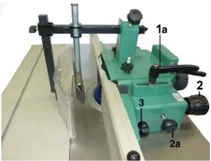
Fig. 'J'
Fig. 'K'
Rectification
natural_image
Technical line drawing of a mechanical component with threaded ports and mounting base (no text or symbols)natural_image
Green mechanical device with labeled components and transparent base, no visible text or symbolsnatural_image
Green laboratory instrument with labeled parts, no visible text or symbolsnatural_image
Industrial machine with layered material and control components, no visible text or symbolsOutillage correct

natural_image
Person using a green mechanical testing machine to adjust a blue liquid in a circular chamber (no visible text or symbols)natural_image
Close-up of a green mechanical device with black clamping mechanism and metallic components (no visible text or symbols)natural_image
Person operating a green cutting machine on a wooden workbench, no visible text or symbolsnatural_image
Mechanical setup with green clamps and wooden components, no visible text or symbols
natural_image
Green industrial machine with labeled components (1, 2, 3, 4) showing wood grain and tool handle (no text or symbols beyond labels)natural_image
Close-up of a glass container with a small object inside, placed on a wooden surface (no visible text or symbols)natural_image
Technical line drawing of two wooden beams or supports, one with visible grain and the other with texture (no text or symbols)natural_image
Simple line drawing of a wooden beam supported by a vertical rod (no text or symbols)natural_image
Technical line drawing of two wooden beams or clamps, showing different structural layers (no text or symbols)natural_image
Simple line drawing of a wooden L-shaped bracket with visible grain texture and no text or symbolsnatural_image
Simple line drawing of a wooden plank with visible grain and texture (no text or symbols)natural_image
Line drawing of a wooden beam joint or bracket (no text or symbols)natural_image
Simple line drawing of a wooden plank with visible grain texture (no text or symbols)natural_image
Technical line drawing of a wooden beam joint with visible grain and fasteners (no text or symbols)natural_image
Technical line drawing of a wooden joint or bracket with no visible text or symbolsnatural_image
Technical line drawing of wooden joint fasteners (no text or symbols)natural_image
Technical line drawing of a wooden post with two notches (no text or symbols)natural_image
Simple line drawing of two wooden beams with a separate support bracket (no text or symbols)natural_image
Technical line drawing of two mechanical components: a wooden bracket and a wooden bracket with a triangular cutout (no text or symbols)natural_image
Illustration of wooden door and shelf, showing a side profile and a close-up of the shelf (no text or symbols)natural_image
Technical line drawing of a wooden joint with clamps (no text or symbols)
natural_image
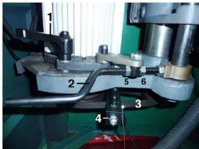
Three-panel image showing a green industrial machine with directional arrows indicating motion, internal components, and a close-up of a mechanical component inside a circular opening (no visible text or symbols)Achtung!
Fence system in the machine
Screw the cover back!
Achtung!
Screws for the fence system in headstock


- Tischfräsmaschine
- Toupie
- Hersteller:
- Abb.: „C“
- Fräsanschlag
- Abb."H"
- Dokumentation
- Abb."K"
- Schleifarbeiten
- Drehzahleinstellung
- Abb. "L"
- Richtiges Rüsten
- Wartung
- Spindle Moulder
- Manufacturer:
- NOTE:
- Recommendations:
- Contents
- GENERAL NOTES 33
- PROPER USE 34
- RESIDUAL RISKS 35
- SCOPE OF DELIVERY 35
- SPECIFICATIONS 36
- INSTALLATION AND ADJUSTMENT 39
- OVERHEAD ROLLER GUARD ASSEMBLY (SUPPLIED AS STANDARD) 39
- CURVED MOULDING GUARD (STANDARD) 39
- ELECTRICAL CONNECTION 40
- FORWARD AND REVERSE DRIVE SWITCH 41
- CONNECTION DIAGRAM FOR 380-420V / 50Hz 43
- CONNECTION DIAGRAM FOR 220-240V / 50Hz 44
- OPERATION 45
- SPEED SETTING 47
- TIPS FOR WORKING 49
- CORRECT SET-UP 50
- DIFFERENT APPLICATIONS FOR THE SPINDLE MOULDER 51
- MAINTENANCE 55
- TENSIONING THE BELT 55
- TROUBLESHOOTING 56
- ACCESSORIES: 56
- EC DECLARATION OF CONFORMITY 57
- WARRANTY 57
- General notes
- Workpiece guidance
- → Rotation direction and speed selection
- Rotation direction
- → Speed selection
- ⇒ Machine operation, selection and adjustment of separating safety devices
- Moulding at the fence where the workpiece is being tooled along its full length
- Moulding the long side and front side
- → Curved moulding
- → Insert moulding
- → Tenon cutting and grooves
- Proper use
- Residual risks
- Scope of delivery
- Molda 5.0f Spindle Moulder
- Structural dimensions:
- Moulding spindle:
- Dimensions of machinable workpieces:
- Operating conditions:
- Storage conditions:
- Noise parameters
- Note
- Installation and adjustment
- Height compensation
- Figure A
- Caution!
- Overhead roller guard assembly (supplied as standard)
- Figure B
- Figure C
- Curved moulding guard (optional)
- Bearing ring
- Supplementary set for curved moulding fence (optional)
- Curved fence plates
- Electrical connection
- Forward and reverse drive switch
- Motor brake
- Operating mode/operating time
- Defective electrical connection cables
- Possible causes are:
- Three-phase current motor
- Connection diagram for 220-240V / 50Hz
- peration
- Moulding tool and insert ring
- Figure G
- oulding fence
- Figure H
- Fine adjustment of the moulding depth
- Setting the fence profile
- Curved moulding fence
- Inserting the curved fence plates
- Figure I
- Settings
- Figure J
- External radii
- Speed setting
- Moulding spindle adjustment
- !! Caution!
- Spindle height adjustment: 95mm
- Figure N
- Tips for working
- Disconnect the mains plug!
- Workpiece guidance, figure O
- The feed direction of the workpiece always depends on the motor direction.
- Workpiece feed direction
- Workpiece – pushing from above
- Workpiece – pushing from the side
- Moulding tool – direction
- Overhead roller guard assembly, figure P
- Safety distance when using the power feed device
- Figure Q
- Inserting the guide rail
- Correct set-up
- The requirement for working safely!
- Replacing the moulding tool
- Figure R
- Different applications for the spindle moulder
- Moulding the long side
- Safety note:
- Moulding the front end
- Insert moulding
- Figure U
- Corrosion protection: (accessory) article no.: 6100 9800
- Application of various moulding tools
- Wood joints
- Maintenance
- Tensioning the belt
- Figure Z
- Troubleshooting
- EC Declaration of Conformity
- We, S
- Molda 5.0f
- Fabricant :
- Cher client,
- Fig.: 'C'
- Fig. 'K'
- Rectification
- Outillage correct
- Achtung!
Brand : SCHEPPACH
Model : Molda 5.0f
Category : Milling machine