PAC 9.3 Compact - Air Conditioning Eurom - Free user manual and instructions
Find the device manual for free PAC 9.3 Compact Eurom in PDF.

| Product type | Portable monoblock air conditioner |
| Brand | Eurom |
| Model | PAC 9.3 Compact |
| Dimensions (W x D x H) | 285 x 335 x 698 mm |
| Net weight | 22 kg |
| Power supply | 220-240 V ~ 50 Hz |
| Power consumption (cooling) | 1000 W |
| Rated current (cooling) | 4.5 A |
| Cooling capacity | 2600 W / 8900 BTU/h |
| Refrigerant | R290 (propane) – 140 g |
| Airflow (max/min) | 340 / 300 m³/h |
| Hot air exhaust hose | Diameter 152 mm, length 1500 mm |
| Fuse | Ceramic fuse T 250 V AC 3.15 A |
| Operating temperature range | 16 °C to 35 °C |
| Protection rating | IPX0 |
| Sound power level | 65 dB(A) |
| Sound pressure level | 55 dB(A) |
| Operating modes | Cooling, dehumidification, ventilation, sleep |
| Special functions | Timer 1-24 h, remote control, antifrost protection, compressor protection |
| Maintenance and cleaning | Clean filters every 2 weeks; vacuum grilles; clean with a damp cloth |
| Safety | Automatic shut-off when tank is full; overheating protection; use of R290 refrigerant (flammable) – see precautions |
| Warranty | 36 months (excluding normal wear) |
| Included accessories | Remote control, window kit, hot air hose, drain hose |
| Recommended area (low heat load) | 29 m² / 80 m³ |
| Recommended area (high heat load) | 18 m² / 50 m³ |
Frequently Asked Questions - PAC 9.3 Compact Eurom
User questions about PAC 9.3 Compact Eurom
0 question about this device. Answer the ones you know or ask your own.
Ask a new question about this device
Download the instructions for your Air Conditioning in PDF format for free! Find your manual PAC 9.3 Compact - Eurom and take your electronic device back in hand. On this page are published all the documents necessary for the use of your device. PAC 9.3 Compact by Eurom.
USER MANUAL PAC 9.3 Compact Eurom
natural_image
White portable air purifier with black mesh ventilation grille and wheels (no visible text or symbols)Model: PAC 7.3 Compact
PAC 9.3 Compact
PAC 12.3 Compact
Date: 19/12/2025
Version: v2.0
EUROM®
POWERFUL PRODUCTS SINCE 1974
Model: Product code:
PAC 7.3 Compact 380767
PAC 9.3 Compact 380774
PAC 12.3 Compact 380743
Order link for optional accessories

Figuur 4.
natural_image
3D diagram of a rectangular object with a 45-degree angle marked on its side, showing no text or symbols.Figuur 7.
natural_image
Illustration of a portable air conditioner unit with a 50 cm height measurement and circular motion lines (no text or symbols on the device itself)Figuur 8.
Figuur 9.

Figuur 10.
Figuur 11.
Figuur 12.
Figuur 13.
natural_image
Diagram of a server unit connected to an electrical outlet, showing airflow path and connection point (no text or symbols)Figuur 14.
Figuur 15.
Figuur 16.
Werking

WAARSCHUWING
natural_image
Diagram showing a mechanical component with directional arrows and numbered label (1), set against a striped background (no readable text or symbols)Figuur 17.
Ventilatormodus
Figuur 18.
Figuur 19.
Please read and understand these safety instructions. Incorrect use can cause injury and/or property damage and will void EUROM's warranty.
- Read all the safety instructions carefully before use and keep this instructions for further use.
- This appliance can be used by children aged from 8 years and above and persons with reduced physical, sensory or mental capabilities or lack of experience and knowledge if they have been given supervision or instruction concerning use of the appliance in a safe way and understand the hazards involved.
•Children shall not play with the appliance. - Cleaning and user maintenance shall not be made by children without supervision.
•The appliance shall be installed in accordance with national wiring regulations.
•The appliance contains Explosion-Proof Ceramic Fuse T 250 V AC, 3,15A. - If the supply cord is damaged, it must be replaced by the manufacturer, its service agent or similarly qualified persons in order to avoid a hazard.
WARNING
This device is filled with the flammable propane gas R290 refrigerant. There is a risk of fire, if R290 leaks and is exposed to an ignition source. Make sure the device is not damaged, a leak is difficult to detect because R290 is odorless and heavier then air. If a leak is detected, immediately evacuate all persons from the area, ventilate the area and contact the local fire department to inform them that a propane leak has occurred.
Specific information regarding appliances with R290 refrigerant gas. Thoroughly read all of the warnings.
•R290 is a refrigerant gas that complies with the European directives on the environment.
•Compliance with national gas regulations shall be observed.
- This appliance contains R290 refrigerant gas (see rating label back of unit), which is highly flammable and can cause health and environmental damage if not handled properly.
°PAC 7.3 Compact: 80 gr.
°PAC 9.3 Compact: 140 gr.
°PAC 12.3 Compact: 175 gr.
- The appliance shall be installed, operated and stored in a room without activated ignition sources (for example: open flames, an activated gas appliance or an activated electric heater).
- Appliance shall be installed, operated and stored in a room with a floor area larger than:
°PAC 7.3 Compact: 4m ^2
°PAC 9.3 Compact: 12m ^2
°PAC 12.3 Compact: 12m ^2
- Be aware that refrigerants do not have a discernible odour – you cannot smell a gas leak!
- Always provide some ventilation in the room where the appliance is installed, operated and stored. Ventilation openings must always be freely permeable and must not be blocked.
-
The area in which the appliance is located must be constructed in such a way that any escaping refrigerant gas cannot accumulate.
-
The appliance must be installed, operated and stored in such a way that any mechanical defects are prevented.
- Do not pierce or burn.
- Avoid contact with the refrigerant and do not perforate any part of the refrigerant circuit and do not set the appliance on fire.
- Ducts connected to an appliance shall not contain a potential ignition source.
- Do not use means to accelerate the defrosting process or to clean, other than those recommended by the manufacturer.
- When defrosting and cleaning the appliance, do not use any tools other than those recommended by the manufacturing company.
- Individuals who operate or work on the refrigerant circuit must have the appropriate certification issued by an accredited organization that ensures competence in handling refrigerants according to a specific evaluation recognized by associations in the industry.
- Repairs must be performed based on the recommendation from the manufacturing company. Maintenance and repairs that require the assistance of other qualified personnel must be performed under the supervision of an individual specified in the use of flammable refrigerants.
Considering this is an appliance using R290 refrigerants, a service and operation manual for this appliance is available on request. It is strictly forbidden for end-users to charge refrigerant by themselves. The refrigerant may only be charged or discharged by certified specialist personnel.
General safety instructions

WARNING
RISK OF ELECTRIC SHOCK!
- Only connect the appliance if the mains voltage of the socket corresponds to the specification on the rating plate.
- Only connect the appliance to an easily accessible socket so that you can quickly disconnect the appliance from the mains in the event of a fault.
- Do not operate the appliance if it has visible damage or if the mains cable or plug is defective.
- Do not use the air conditioner with an device that automatically switches the air conditioner on, such as a timer, dimmer or any other device or with a separate remote control system.
- Do not pull, deform or modify the power supply cord, or immerse it in water. Pulling or misuse of the power supply cord can result in damage to the unit and cause electrical shock.
- Never touch the mains plug with wet hands. Never reach for an electrical appliance if it has fallen into the water.
- Never pull the mains plug out of the socket by the mains cable, always grasp the mains plug.
- Never use the power cord as a carrying handle.
- Lay the mains cable so that it does not become a tripping hazard.
- Do not bend the mains cable or place it over sharp edges.
-
Do not bring the mains cable into contact with hot parts.
•The appliance is for indoor use only. -
Do not use the appliance if any parts are dirty or wet.
- Do not operate or stop the appliance by inserting or pulling out the power plug, it may cause electric shock or fire due to heat generation.
- Do not use the appliance (follow these precautions):
°Near a source of fire.
°In an area where oil is likely to splash.
• In an area exposed to direct sunlight.
°In an area where water is likely to splash.
°Near a water source like sink, bath, a laundry, a shower or a swimming pool.
°Near or in a dusty and dirty environment, like a construction site.
•Near flammable gases, materials, liquids or fumes, like an insect repellent spray, gas cylinder or gas pipes.
°Near a heat source, ignition source or open fire, like cigarettes and sparking electrical equipment.
- Avoid using spray cans near the product.
WARNING
FIRE HAZARD!
- Do not touch the hot parts of the appliance with bare fingers during operation. Also point out the dangers to other users!
- To avoid the possibility of fire disaster, the air conditioner shall not be covered.
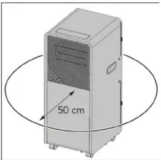
- Place the appliance with a minimum clearance distance of 50 cm on all sides (top and 360° around).
- Unplug the appliance if strange sounds, smell or smoke come from it.
- Do not leave the appliance unattended during operation.

WARNING
RISK OF INJURY OR DAMAGE!
- Never insert your fingers or objects into the air inlets or outlets. Take special care to warn children of these dangers. Draw the attention of children in particular to this danger.
- Keep long hairs away from the appliance. These can be sucked in through the air inlets.
- Do not use the appliance lying, leaning, hanging or tilted.
- Place the appliance on an easily accessible, level, dry, heat-resistant and sufficiently stable work surface.
- The appliance is on castors. Make sure that it is always on a level surface and cannot roll away.
- Keep the appliance upright during transport and storage, for the compressor locates properly.
- When moving the appliance, always turn off and disconnect the power supply, and move it slowly.
-
Keep ventilation openings clear of obstruction.
-
When you are not using the appliance, cleaning it or if a malfunction occurs, always switch off the appliance and disconnect the mains plug from the socket. Note that certain parts of the appliance may still be hot after it has been switched off.
- For safety reasons, do not leave the house with the windows open to let the hot air out of the appliance.

WARNING
- Prevent splashing water on or in the device.
- Do not immerse any part of the device in water or other liquids.
- Never insert fingers or other objects into the openings of the device.
- Do not expose the device to strong vibrations or mechanical stress.

CAUTION
Make sure the device remains upright at all times. If, however, the device or part of it has been lying horizontally, wait 24 hours before use.

CAUTION
Do not cover the device during usage. To reduce the risk of fire, keep textiles, curtains, tent canvasses and other flammable material at a minimum distance of 50 centimeters from the device.
- If any parts are damaged, please contact the dealer or a designated repair shop.
- In case of any damage, please turn off the air conditioner, disconnect the power supply, and contact the dealer or a designated repair shop.
• In any case, the power cord shall be firmly grounded. - To avoid the possibility of danger, if power cord is damaged, please turn off the air conditioner and disconnect the power supply. It must be replaced from the dealer or a designated repair shop.
Information about batteries

WARNING
Keep out of the reach of children. If swallowed, they may cause injuries and lead to the perforation of soft tissue and ensuing death. Severe burns may be incurred within 2 hours of intake. Consult a physician immediately.
WARNING
Replacing the battery incorrectly might result in an explosion. Replace the battery only with the same or equivalent type recommended by the manufacturer. Dispose of used batteries according to the manufacturer's instructions.
- Incorrect handling of batteries may cause fire, explosions, the leakage of hazardous substances or further hazardous situations!
-
Do not fling the batteries into a fire and do not subject them to high temperatures.
-
Neither open, deform nor short-circuit batteries as this may cause the chemicals they contain to escape.
- Do not try to recharge batteries. Only batteries marked as “rechargeable” may be recharged. There is danger of explosion!
•Always remove rechargeable batteries from the appliance for recharging. - Test the batteries regularly. Chemicals which leak may cause long-term damages to the appliance. Be particularly careful when handling damaged or leaking batteries.
- Danger of chemical burn! Wear protective gloves.
•Chemicals which leak from a battery may cause skin irritations. - In case of skin contact, rinse with ample water. If the chemicals have come into contact with the eyes, always rinse them with water, do not rub them and consult a physician immediately.
- Neither use different battery nor rechargeable battery types nor mix old and new batteries.
- Always insert batteries with the correct polarity, because otherwise the danger of bursting exists.
- Remove the batteries from the appliance if you do not wish to use it for a longer period or wish to store it.
- Do not allow children to replace the batteries without adult supervision.
- Always select the correct size and battery type for the intended use. The information provided with the appliance for supporting the correct battery selection should be kept as a reference.
- Clean the battery contacts and also the equipment's contacts before installing the battery.
- Remove used batteries without delay and dispose of them in an environmentally responsible manner.
- Do not dismantle batteries.
- If the battery compartment cover doesn't close properly, do not use the remote control any longer and keep it out of the reach of children.
- Avoid extreme conditions and temperatures which can influence batteries / rechargeable batteries, e.g. placing them on radiators / direct insolation.
Warranty
EUROM offers a 36-month warranty on this device from the date of purchase. The warranty does not cover wear and tear from normal use. The warranty expires if a defect is the result of unintentional or careless use of the device. The manufacturer, importer and supplier are not liable for incorrect connections.
Introduction
Thank you for choosing this EUROM device. You have purchased a quality device that you will enjoy for many years. Using this device with respect and care will reduce the risk of personal injury or material damage.

CAUTION
It is important to read and understand this instruction manual before assembling, installing and using the device.
This manual describes the correct and safe use of this device. Keep this manual for future reference. The manual is an essential part of the device and must be given to the new owner upon resale or exchange. This manual has been compiled with the utmost care. Nevertheless, we reserve the right to improve and adjust this manual at any time. The images used may differ.
The following symbols and terms are used in this manual to alert the reader to safety issues and important information:

WARNING
Indicates a hazardous situation which, if the safety instructions are not followed, can lead to injuries to the operator or bystanders, light and/or moderate damage to the product or to the environment.

CAUTION
Indicates a hazardous situation which, if the safety instructions are not followed, can lead to light and/or moderate damage to the product or to the environment.
Symbols on the information label
The product is provided with an information label. The information label contains the following symbols:
| Symbol Description | |
 | Read all safety information and instructions. |
 | If repairs are required, please contact the nearest service centre and follow the manufacturer's instructions exclusively and precisely. |
Identification
| EUROM®POWERFUL PRODUCTS SINCE 1974 | PAC 7.3 CompactArt.nr. 380767 | |||
| BATCH | BE0000 | |||
| COOLING CAPACITY | 2000W / 6900 BTU | |||
| HEATING CAPACITY | ---- | |||
| REFRIGERANT | R290/80g | |||
| PERMISSIBLE EXCESSIVEOPERATING PRESSURE | DISCHARGE 2,6Mpa | |||
| SUCTION 1.0MPa | ||||
| MAX ALLOWABLE PRESSURE | DISCHARGE 3.2MPa | |||
| SUCTION 1.2MPa | ||||
| RATED VOLTAGE | 220-240V~ | |||
| RATED FREQUENCY | 50Hz | |||
| STANDARD RATING CONDITIONS | CURRENT | COOLING | 3.4A | |
| HEATING | ---- | |||
| INPUT | COOLING | 769W | ||
| HEATING | ---- | |||
| RATED CURRENT | COOLING | 3.5A | ||
| HEATING | ---- | |||
| RATED INPUT | COOLING | 785W | ||
| HEATING | ---- | |||
| RESISTANCE CLASS | IPX0 | |||
| DIMENSION(mm) | 285*335*698 | |||
| SOUND POWER LEVEL | 65dB(A) | |||
| SOUND PRESSURE LEVEL | 55dB(A) | |||
     | ||||
| Eurom - Kokosstraat 20 - 8281 JC Genemuiden - The Netherlandsinfo@eurom.nl | ||||
Figure 20.
| EUROM®POWERFUL PRODUCTS SINCE 1974 | PAC 9.3 CompactArt.nr. 380774 | ||
| BATCH | BE0000 | ||
| COOLING CAPACITY | 2600W / 8900 BTU | ||
| HEATING CAPACITY | ---- | ||
| REFRIGERANT | R290/140g | ||
| PERMISSIBLE EXCESSIVEOPERATING PRESSURE | DISCHARGE 2,6Mpa | ||
| SUCTION 1.0MPa | |||
| MAX ALLOWABLE PRESSURE | DISCHARGE 3.2MPa | ||
| SUCTION 1.2MPa | |||
| RATED VOLTAGE | 220-240V~ | ||
| RATED FREQUENCY | 50Hz | ||
| STANDARD RATING CONDITIONS | CURRENT | COOLING | 4.5A |
| HEATING | ---- | ||
| INPUT | COOLING | 1000W | |
| HEATING | ---- | ||
| RATED CURRENT | COOLING | 4.5A | |
| HEATING | ---- | ||
| RATED INPUT | COOLING | 1000W | |
| HEATING | ---- | ||
| RESISTANCE CLASS | IPX0 | ||
| DIMENSION(mm) | 285*335*698 | ||
| SOUND POWER LEVEL | 65dB(A) | ||
| SOUND PRESSURE LEVEL | 55dB(A) | ||
    | |||
| Eurom - Kokosstraat 20 - 8281 JC Genemuiden - The Netherlandsinfo@eurom.nl | |||
Figure 21.
| EUROM®POWERFUL PRODUCTS SINCE 1974 | PAC 12.3 CompactArt.nr. 380743 | ||
| BATCH | BE0000 | ||
| COOLING CAPACITY | 3500W / 12000 BTU | ||
| HEATING CAPACITY | ---- | ||
| REFRIGERANT | R290/175g | ||
| PERMISSIBLE EXCESSIVEOPERATING PRESSURE | DISCHARGE 2,6Mpa | ||
| SUCTION 1.0MPa | |||
| MAX ALLOWABLE PRESSURE | DISCHARGE 3.2MPa | ||
| SUCTION 1.2MPa | |||
| RATED VOLTAGE | 220-240V~ | ||
| RATED FREQUENCY | 50Hz | ||
| STANDARD RATING CONDITIONS | CURRENT | COOLING | 5.9A |
| HEATING | ---- | ||
| INPUT | COOLING | 1346W | |
| HEATING | ---- | ||
| RATED CURRENT | COOLING | 5.9A | |
| HEATING | ---- | ||
| RATED INPUT | COOLING | 1346W | |
| HEATING | ---- | ||
| RESISTANCE CLASS | IPX0 | ||
| DIMENSION(mm) | 285*335*698 | ||
| SOUND POWER LEVEL | 65dB(A) | ||
| SOUND PRESSURE LEVEL | 55dB(A) | ||
  | |||
| Eurom - Kokosstraat 20 - 8281 JC Genemuiden - The Netherlandsinfo@eurom.nl | |||
Figure 22.
Specifications
| Type PAC 7.3 | Compact PAC 9.3 Compact | PAC 12.3 Compact | |
| Product size: | 285 x 335 x 698mm | 285 x 335 x 698mm | 285 x 335 x 698mm |
| Weight: | 21kg | 22kg | 24kg |
| Voltage: | 220 - 240V / 50Hz | 220 - 240V / 50Hz | 220 - 240V / 50Hz |
| Current consumption: | 3.5A (cooling) | 4.5A (cooling) | 5.9A (cooling) |
| Cooling capacity: | 2,000W (6,900Btu) | 2,600W (8,900Btu) | 3,500W (12,000Btu) |
| Cooling liquid: | R290 (80g) R290 (140g) R290 (175g) | ||
| Airflow: 240/2 | 80m ^3 | 300/340m ^3 | 280/320m ^3 |
| Drain pipe size: | ∅ 152 x 1500mm ∅ 152 x | 1500mm ∅ 152 x 1500mm | |
| Fuse: | Explosion-proof ceramic fuse T 250V AC 3.15A | Explosion-proof ceramic fuse T 250V AC 3.15A | Explosion-proof ceramic fuse T 250V AC 3.15A |
| Working temperature: | 16-35°C 16-35°C 16-35°C | ||
| Protection rating: | IPX0 IPX0 IPX0 | ||
| Sound power level: | 65dB(A) 65dB(A) 65dB(A) | ||
| Sound pressure level: | 55dB(A) 55dB(A) 55dB(A) | ||
Maximum effect usage
The maximum surface area that this air conditioner can cool depends on several factors:
•outside temperature;
• number and/or size of windows;
- flat roof;
• people in the space;
•electrical equipment in the space.
When these factors are present to a lesser extent (so-called low heat loads), the device can cool a larger surface area than when these factors are present to a greater extent (so-called high heat loads).
| Type PAC 7.3 Compact PAC 9.3 Compact PAC 12.3 Compact | |||
| Low heat loads | 22 m^2 / 60 m^3 | 29 m^2 / 80 m^3 | 38 m^2 / 105 m^3 |
| High heat loads | 14 m^2 / 40 m^3 | 18 m^2 / 50 m^3 | 24 m^2 / 66 m^3 |
Description
The PAC 7.3/9.3/12.3 Compact is an easy-to-use portable air conditioner for domestic indoor use only. The device provides continuous cooling and drains the condensed water automatically.
The device is equipped with an overheating protection, which switches it off automatically in case of internal overheating. Unplug the power plug, remove the source of overheating, let the
device cool down and use as normal. Do not use the device if the source of overheating cannot be traced or if the problem persists, but always contact your supplier.
Unboxing

WARNING
Plastic bags can be dangerous. To avoid danger of suffocation, keep these bags away from babies and children.
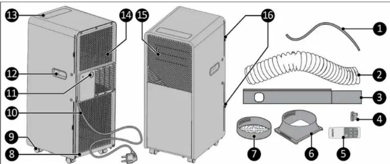
Figure 23.
| No. | Description No. Description | ||
| 1. | Water drain hose 9. Wheels | ||
| 2. | Hot air outlet hose 10. Power cable | ||
| 3. | Window kit 11. Water discharge point | ||
| 4. | Window kit dowel (2x) 12. Handle (2x) | ||
| 5. | Remote control 13. Control panel | ||
| 6. | Hose connector 14. Air inflow grilles | ||
| 7. | Window kit connector 15. Air outflow louvers | ||
| 8. | Drain 16. Filter (2x) |
Control panel
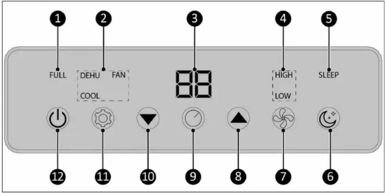
Figure 24.
| No. | Description No. Description | ||
| 1. | Water full indicator 7. Fan speed button | ||
| 2. | Mode indicator 8. Temperature up button | ||
| 3. | Temperature and timer indicator 9. Timer button | ||
| 4. | Fan speed indicator 10. Temperature down button | ||
| 5. | Sleep mode indicator 11. Mode button | ||
| 6. | Sleep mode button 12. ON/OFF button |
Remote control

ATTENTION
Batteries not included.
- Temperature up button
- Mode button
- Temperature down button
- Timer button
- Power button
- Sleep mode button
- Fan speed button
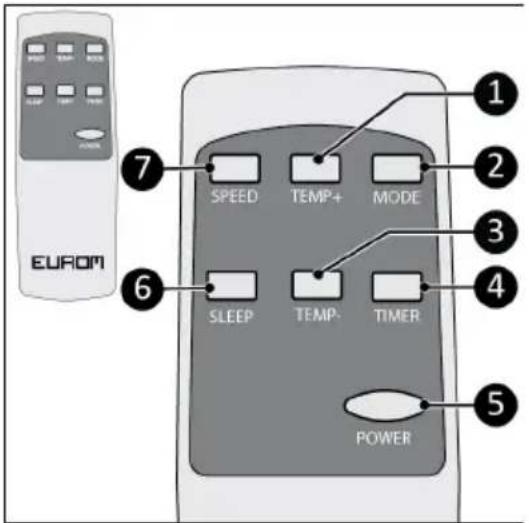
Figure 25.
Transport and storage
- Clean the device before storing it.
- Transport the device in an upright position.
- Store the device in an upright position, in its original packaging, in a cool, dry, ventilated and dust-free area larger than:
- PAC 7.3 Compact: 4m^2
- PAC 9.3 Compact: 12m^2
°PAC 12.3 Compact: 12m ^2
Installation

WARNING
- Do not put the power plug into the wall socket before the device is mounted or placed correctly.
- Do not use an extension cable; this can cause overheating and fire. If using an extension cable is unavoidable, make sure it is undamaged and earthed. Use an extension cable with a minimum power of 800 Watt, (PAC 7.3 Compact), 1000 Watt (PAC 9.3 Compact), or 1400 Watt (PAC 12.3 Compact). Always unwind the extension cable completely to prevent overheating.

CAUTION
Make sure that the main voltage is the same as indicated on the identification label of the device. All electrical connections must stay dry under all circumstances.
The device is packed in one box. Remove all packaging material and check that the device is not damaged. Do not use the device if it is damaged, but always contact your supplier. Keep the packaging for safe storage and transport.
- The device can be moved from room to room. Make sure to not tilt the device more than 45 degrees.
-
Place the device on a firm and horizontal surface near a power socket and an outlet possibility.
-
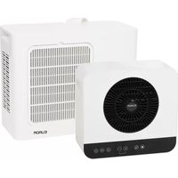
Place the device with a minimum clearance distance of 50 cm on all sides.
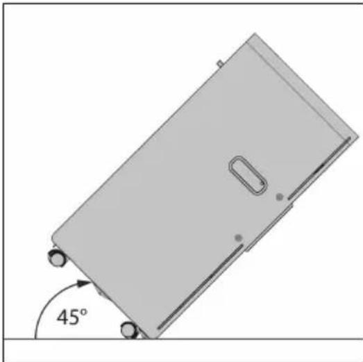
natural_image
3D diagram of a rectangular object with a 45-degree angle marked on its side, showing no text or symbols.Figure 26.

natural_image
Illustration of a portable air conditioner unit with a 50 cm height measurement and circular motion lines (no text or symbols on the device itself)Figure 27.
Installation to cool
-
Connect the hose connector (Figure 28, pos. 2) to one end of the hot air outlet hose (Figure 28, pos. 1).
-
Connect the window kit connector (Figure 29, pos. 2) to the other end of the hot air outlet hose (Figure 29, pos. 1).
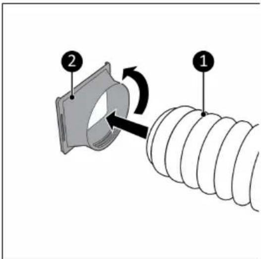
Figure 28.
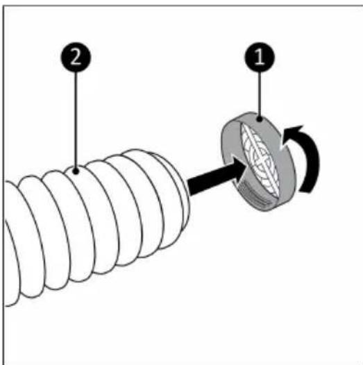
Figure 29.
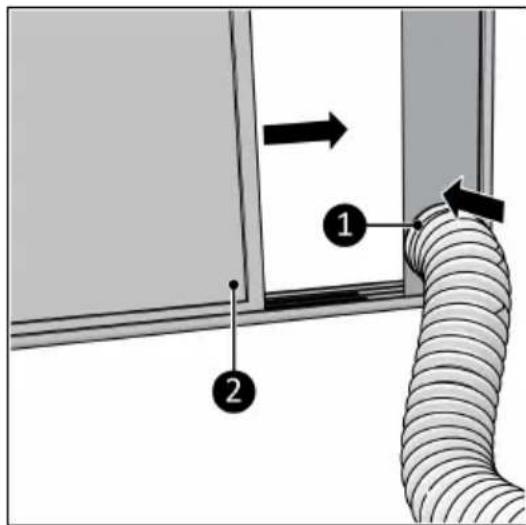
- Place the included window connector kit in the opening of the window (Figure 30, pos. 3).
- Use the top part (Figure 30, pos. 1) to adjust to the height of the window. Attach the two parts in the right positions with the included dowels (Figure 30, pos. 2).
The window kit only works with a sliding window. For other windows we recommend the EUROM Window Way-out.
Order link for optional accessories:

- Close the window (Figure 31, pos. 2). This will hold the window kit in place.
- Connect the window kit connector to the window kit (Figure 31, pos. 1).
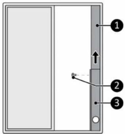
Figure 30.
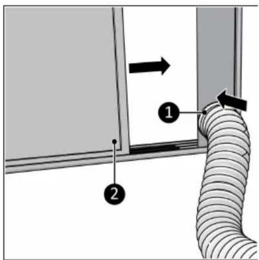
Figure 31.
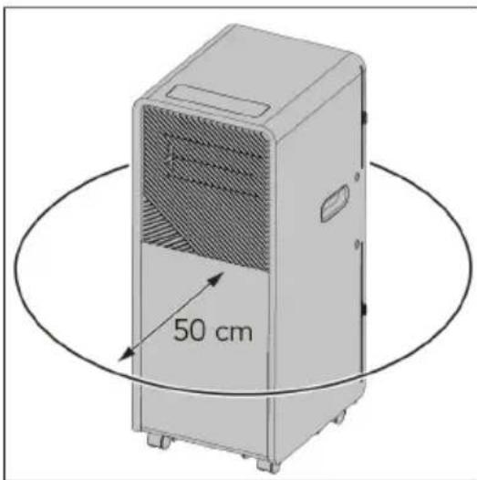
- Connect the hose connector (Figure 32, pos. 1) to the hot air outlet of the device (Figure 32, pos. 2).
Avoid kinks or bends in the hot air outlet hose.
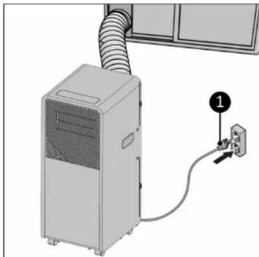
- Place the power plug (Figure 33, pos. 1) into an earthed wall socket that is easily accessible. Use an earthed wall socket with a minimum power of:
• PAC 7.3 Compact: 800 Watt
• PAC 9.3 Compact: 1000 Watt
• PAC 12.3 Compact: 1400 Watt
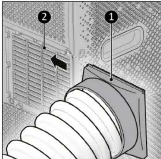
Figure 32.

natural_image
Diagram of a server unit connected to an electrical outlet, showing airflow path and connection point (no text or symbols)Figure 33.
Installation to dehumidify
- Make sure the device is switched off and the plug is removed from the power outlet (Figure 34, pos. 2).
- Remove the rubber plug from the drain (Figure 34, pos. 4).
- Connect the included water drain hose (Figure 34, pos. 1) to the drain of the device.
- Place the outlet of the water drain hose in a bucket (Figure 34, pos. 3).
- Regularly check the water level in the bucket. The end of the hose should not be immersed in water.
In the dehumidifying mode it is not necessary to mount the hot air outlet hose.
Remote control
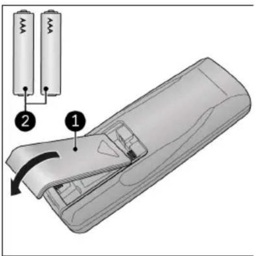
- Remove the cover (Figure 35, pos. 1).
- Remove the batteries (if present).
- Insert two batteries (AAA 1.5V) (Figure 35, pos. 2) in the battery compartment as indicated. Make sure to insert the batteries correctly.
- Replace the cover.
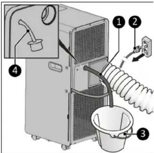
Figure 34.

Figure 35.
Operation

WARNING
Before every use, make sure that:
•you operate the device with dry hands;
•the device is clean and dry;
• the device is not damaged;
•the device is not covered or blocked;
•the louvers are open;
• the device stands securely and horizontally.
- Make sure the device is correctly installed.
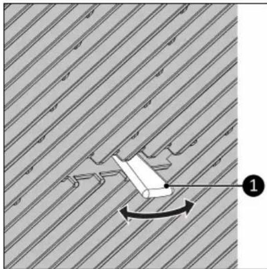
- Adjust the louvers by moving the handle left/right (Figure 36, pos. 1) to change the wind direction.
- Press the ON/OFF button on the device or the remote control. The device will start in Fan mode.
- Press the Mode button on the device or on the remote control to select the desired mode.
natural_image
Diagram showing a mechanical component with directional arrow and numbered label (1), set against a striped background (no readable text or symbols)Figure 36.
Fan mode
- Press the Speed button on the device or on the remote control to select the desired fan speed (Low-High).
Cooling mode
- Press the Up or Down button to set the required temperature (16 °C-31 °C).
- Press the Speed button on the device or on the remote control to select the desired fan speed (Low-High).
- The device will stop cooling when the ambient temperature is lower than the required temperature.
Dehumidify mode
- Follow the instructions for Installation to dehumidify before choosing this mode.
- Regularly check the water level in the bucket, the end of the hose should not be immersed in water.
Timer
The device can automatically start and stop at a preset time.
Automatically start
- Set the device to the desired mode and the desired temperature.
- Press the ON/OFF button, the device is now in standby mode.
- Press the Timer button.
- Use the Up and Down buttons to set the countdown timer. The device will automatically start (1-24 hours).
- Press the Timer button. The display shows the selected time until the device starts.
Automatically stop
- Set the device to the desired mode and the desired temperature.
- Press the Timer button.
- Use the Up and Down button(s) to set the countdown timer. The device will automatically stop (1-24 hours).
- Press the Timer button. The display shows the timer indication and the selected temperature.
Deactivate timer
To deactivate the timer function, press the "Timer" button until the timer indicator turns off.
Sleep mode
- While in cooling mode, press the Sleep button to set the temperature. It increases 1 °C after an hour and at most increases 2 °C after 2 hours.
- Press the Sleep button again to cancel the setting.
Drainage of condensed water
The device extracts water from the air. The water is partially evaporated with the discharge of the warm air. The remaining water accumulates in the water tank. When the tank is full the device stops automatically and the message Ft will appear on the display.
-
Make sure the device is switched off and the plug is removed from the power outlet (Figure 37, pos. 1).
-
Remove the cap (Figure 37, pos. 3) from the water drainage point (Figure 37, pos. 2).
-
Drain the tank in a container or a well.
-
Don't forget to put the cap back on the water drainage point.
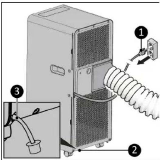
Figure 37.
Compressor protection function
The compressor protection function gives the compressor a 3-minute delay to protect the device. When using functions for cooling and dehumidifying, keep an interval of at least 3 minutes between each power cycle.
Automatic defrost
Frost is detected when the device is operating in the cooling or dehumidify mode and the built-in temperature sensor detects that the temperature is lower than -1 °C. The compressor will stop temporarily. The device starts to defrost automatically and indicator lights start blinking. After the temperature has risen sufficiently, the compressor will start working automatically.
After operation

CAUTION
Do not use the power cable to unplug or carry the device. Do not wind the power cable too tightly or in sharp corners. Do not wrap the power cable around the device.
- Make sure the device is switched off and the plug is removed from the power outlet.
- Let the device cool down before touching it.
- Remove the hot air outlet hose from the window.
- Wind the power cable.
Maintenance

WARNING
Do not perform any repairs or modifications to this device.
Maintenance and repairs must be carried out by a EUROM authorized professional. If the electric cable and/or electric plug is damaged, it should be replaced by the manufacturer or its service employee or persons with similar qualifications to prevent risks.
Repairs must be carried out in accordance with the appliance manufacturer's recommendations. Maintenance and repairs requiring the assistance of other qualified personnel must be carried out under the supervision of a person specialized in the use of flammable refrigerant media. National gas regulations must be complied with. Persons working with or intervening in a refrigerant circuit must hold appropriate certification issued by an accredited body certifying that the person concerned is competent to handle refrigerant media in accordance with a special assessment recognized by industry associations. All parts are specially designed for use in air conditioners with R290 refrigerant. These parts are non-incendiary and should only be replaced with identical repair parts.
Cleaning

CAUTION
Do not use:
•scouring pads;
- hard brushes;
- flammable, aggressive or chemical cleaning products.
Prevent water from entering the device. Do not immerse any part of the device in water or other liquids.
It is recommended to clean the device after each use and prior to storage.
- Make sure the device is switched off and the plug is removed from the power outlet.
- Carefully vacuum the openings to remove dust and dirt.
- Wipe the device with a damp, clean, soft, lint-free cloth or a soft brush.
- Let the device dry completely prior to use and storage.
Filter cleaning
In a season when the device is used regularly, clean the filters every two weeks.
Never use the device without the filters.
- Make sure the device is switched off an the plug is removed from the power outlet.
- Remove the hose connector from the hot air outlet of the device.
- The device has two filters on inside of the device. Pull out both filters (Figure 38, pos. 1 & 2) from the side of the device.
- Carefully vacuum the filters.
- The filters can be cleaned with lukewarm water.
- Let the filters dry completely prior to returning them to their place.
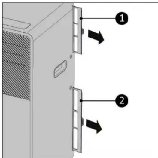
Figure 38.
End-of-season cleaning
- Completely remove the condensed water via the water discharge point.
- Run the device on the fan function for 2 hours.
- Switch off the device and remove the plug from the power outlet.
- Remove the hot air outlet hose from the device and clean and replace both filters.
- Remove the batteries from the remote control.
Troubleshooting
| Issue Possible causes Suggested remedies | ||
| Unit does not start when pressing ON/OFF button | Water full indicator light blinks and water tray is full | Dump the water out of the water tray |
| Room temperature is lower than the temperature setting (cooling mode) | Reset the temperature | |
| Not cool enough | The doors or windows are not closed | Make sure all the doors and windows are closed |
| There are heat sources inside the room | Remove the heat sources if possible | |
| Exhaust air hose is disconnected or blocked | Connect or clean the exhaust air hose | |
| Temperature setting is too high Reset the temperature | ||
| Air inlet is blocked Clean the air inlet | ||
| The ground is not level or not flat enough | Place the unit on flat, level groundN | |
| The sound comes from the flowing of the refrigerant inside the air conditioner | This is normal | |
| E0 code Room temperature sensor failed Have the room temperature sensor replaced (the unit can also work without replacement) | ||
| E1 code Condenser temperature sensor failed | Have the condenser temperature replaced sensor | |
| E2 code Water tray full when cooling Take off rubber stopper and drain the water | ||
| E3 code Evaporator temperature sensor failed | Have the evaporator temperature sensor replaced | |
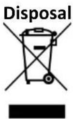
This marking indicates that this product should not be disposed with other household wastes throughout the EU. To prevent possible harm to the environment or human health from uncontrolled waste disposal, recycle it responsibly to promote the sustainable reuse of material.
Dispose of the product in accordance with the local ordinances of your place of residence.
Batteries, rechargeable batteries that are not permanently installed in the device must be removed before disposal and disposed of separately.
Abbildung 42.
natural_image
3D diagram of a rectangular object with a 45-degree angle marked between its side and wheels, no text or symbols present.Abbildung 45.
natural_image
Illustration of a portable air conditioner unit with a 50 cm height measurement and circular motion lines (no text or symbols on the device itself)Abbildung 46.
Abbildung 47.
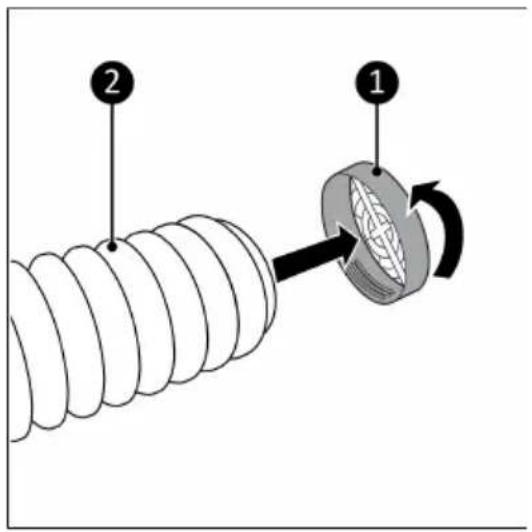
Abbildung 48.
Abbildung 49.
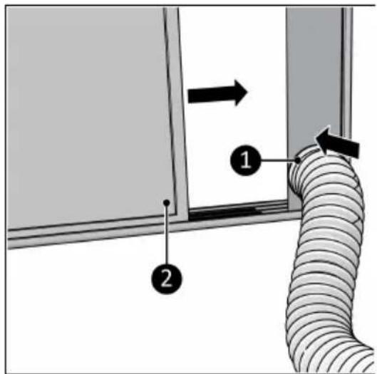
Abbildung 50.
Abbildung 51.
natural_image
Diagram of a desktop air conditioner unit connected to a wall-mounted electrical outlet (no text or symbols visible)Abbildung 52.
Abbildung 53.

Abbildung 54.
Betrieb

WARNUNG
natural_image
Diagram showing a mechanical component with directional arrows and numbered label (1), set against a striped background (no readable text or symbols)Abbildung 55.
Lüfter-Modus
Abbildung 56.
Abbildung 57.
Figure 61.
natural_image
3D diagram of a rectangular object with a 45-degree angle marked on its side, showing no text or symbols.Figure 64.
natural_image
Illustration of a portable air conditioner unit with a 50 cm height measurement and circular motion lines (no text or symbols on the device itself)Figure 65.
Figure 66.

Figure 67.
Figure 68.
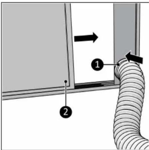
Figure 69.
- Reliez le raccordement de flexible
Figure 70.
natural_image
Diagram of a desktop air conditioner unit connected to a wall-mounted electrical outlet (no text or symbols present)Figure 71.
Figure 72.
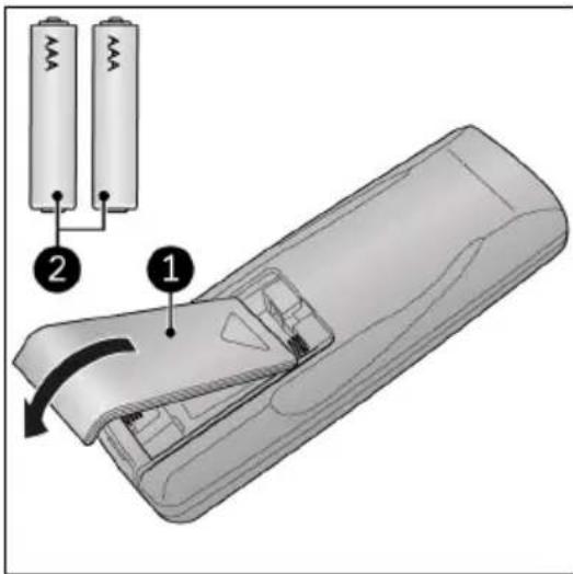
Figure 73.
Utilisation

AVERTISSEMENT
natural_image
Diagram showing a mechanical component with rotational motion, set against a striped background (no text or symbols)Figure 74.
Mode ventilateur
Figure 75.
Figure 76.