
TYTAN101 - Fitness Equipment HMS Premium - Free user manual and instructions
Find the device manual for free TYTAN101 HMS Premium in PDF.

| Product type | Multifunctional gym station |
| Brand | HMS Premium |
| Model | TYTAN101 |
| Net weight | 168 kg |
| Dimensions (unfolded) | 242 × 205 × 219 cm |
| Maximum supported load | 272 kg |
| Maximum user weight | 135 kg |
| Equipment class | H (domestic use) per EN ISO 20957-1 |
| Intended use | Home strength training |
| Main functions | Lat pulldown, bench press, butterfly, leg extension, bicep curl, seated row, etc. |
| Included accessories | Lat bar, V-bar, triceps rope, ankle strap, handles, curl bar, Olympic sleeves |
| Cable system | Steel cables with pulleys |
| Safety | Safety hooks, retaining frames, locking pins |
| Care and cleaning | Damp soft cloth, no harsh chemicals, store dry |
| Warranty | 24 months (under conditions, Poland) |
| Assembly | Required, following detailed instructions |
| Spare parts | Available through after-sales service |
| Materials | Steel, foam, padding |
Frequently Asked Questions - TYTAN101 HMS Premium
User questions about TYTAN101 HMS Premium
0 question about this device. Answer the ones you know or ask your own.
Ask a new question about this device
Download the instructions for your Fitness Equipment in PDF format for free! Find your manual TYTAN101 - HMS Premium and take your electronic device back in hand. On this page are published all the documents necessary for the use of your device. TYTAN101 by HMS Premium.
USER MANUAL TYTAN101 HMS Premium
natural_image
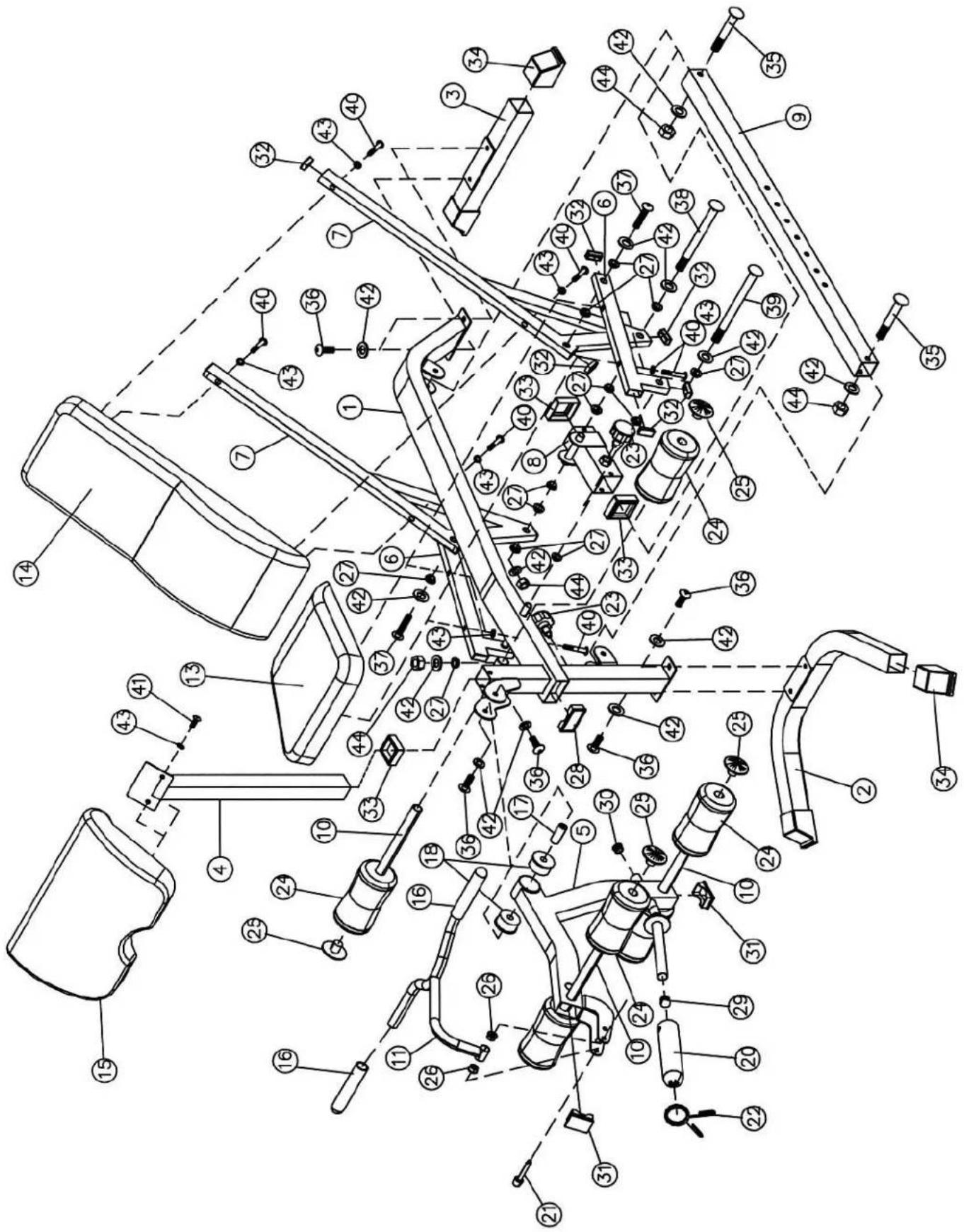
Technical line drawing of a mechanical lifting frame assembly (no text or symbols)-
Manual instruction EN
-
Instrukcja obsługi PL
-
Návod k obsluze CZ
-
Manuel instruktion DA
-
Gebrauchsanweisung DE
-
Manual de instrucciones ES
-
Käsijuhend ET
-
Manuel d'instruction FR
-
Kézi utasítás HU
-
Manuale di istruzioni IT
-
Naudojimo instrukcijos LT
-
Rokasgrāmatas instrukcija LV
-
Handmatige instructie NL
-
Manual de instruções PT
-
Instructiuni manuale RO
-
Návod na obsluhu SK
-
Navodila za uporabo SL
-
Instruktionsbok SV
-
Інструкція з експлуатації UK


natural_image
Simple line drawing of a bolt with a flange and a segmented shaft (no text or symbols)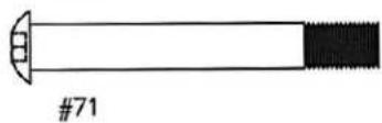

natural_image
Simple line drawing of a bolt with a curved tip and threaded end (no text or symbols)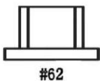
natural_image
Two concentric circles diagram labeled #67, no text or symbols within the shapes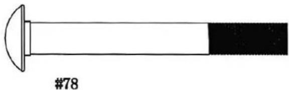
natural_image
Simple line drawing of a mechanical component with a curved top and segmented body (no text or symbols)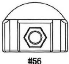
natural_image
Technical line drawing of a mechanical component with a hexagonal nut and curved top (no text or symbols)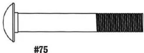
natural_image
Simple line drawing of a bolt with a curved tip and threaded shaft (no text or symbols)


1
7.0
8
10
11

A

B
D
SAFETY NOTES
This product is intended for domestic use only and has been designed to ensure optimum safety. Please observe the following rules:
- Medical consultation – before starting training, consult your doctor to confirm that there are no contraindications to using the equipment. The doctor's decision is particularly important in the case of:
• taking medication that affects heart function, blood pressure or cholesterol levels,
• people over 35 years of age,
• people with health problems.
-
Warm-up – perform an appropriate warm-up before each workout.
-
Reaction to symptoms – pay attention to warning signs. Excessive or improper exercise can be dangerous. In case of pain, dizziness, chest pain, irregular heartbeat or other symptoms, stop exercising immediately and consult your doctor.
- Safety of children and animals – during and after exercise, secure the equipment against access by children and animals.
- Positioning the equipment – place the equipment on a dry, stable and level surface. Remove any sharp objects from the surrounding area, protect the equipment from moisture and level out any unevenness in the ground. We recommend using a non-slip mat to prevent the equipment from moving.
- Free space – ensure that there is at least 0.6 m of free space around the device, greater than the training area in the directions of access. This must also include space for emergency descent. If several devices are placed next to each other, the space may be divided.
- Checking fastenings – before first use and regularly thereafter, check that all screws, bolts and connections are secure.
- Device efficiency – training may only commence when the device is fully operational.
- Regular inspections – the device should be systematically checked for wear and damage. Pay particular attention to the foam handles, leg caps and upholstery. Damaged parts must be repaired or replaced immediately – until then, the equipment must not be used.
- Structural safety – do not insert any objects into the openings of the device.
- Adjustment elements – pay attention to protruding adjustment and structural parts that may interfere with your workout.
- Intended use – only use the equipment for its intended purpose. In the event of damage, wear and tear or disturbing noises, stop exercising immediately and do not use the equipment again until the problem has been rectified.
- Sportswear – exercise in comfortable clothing and sports shoes. Avoid loose clothing that could catch on protruding parts or restrict your movement.
- Equipment class – the equipment has been classified as class H according to EN ISO 20957-1 and is intended for home use only. It must not be used for therapeutic, rehabilitation or commercial purposes.
- Lifting and carrying - maintain proper posture when lifting or carrying the device to avoid straining your back.
- Users – this product is intended for adults only. Keep children away from the device when unsupervised.
- Assembly – when assembling the device, strictly follow the enclosed instructions and use only the parts included in the set. Before starting assembly, check that all components are present according to the list.
WARNING
Read the instructions before using the fitness equipment. The manufacturer is not liable for any injuries to the user or damage to property resulting from improper use of the product.
TECHNICAL DATA
• Net weight: 168 kg
• Dimensions when unfolded: 242 × 205 × 219 cm
• Maximum load: 272 kg
• Maximum user weight: 135 kg
MAINTENANCE
• Do not use aggressive cleaning agents.
• Use a soft, damp cloth to remove dirt and dust.
• Store the device in a dry place to protect it from moisture and corrosion.
INSTALLATION STEPS:
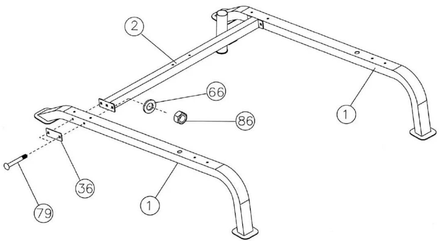
Step 1 (see diagram 1)
Connect the two main frames (1) with the crossbar (2). Secure each end of the crossbar. Note: do not tighten too much.
• 2 screws (79)
- bracket (36)
- washers (66)
• nuts (86)
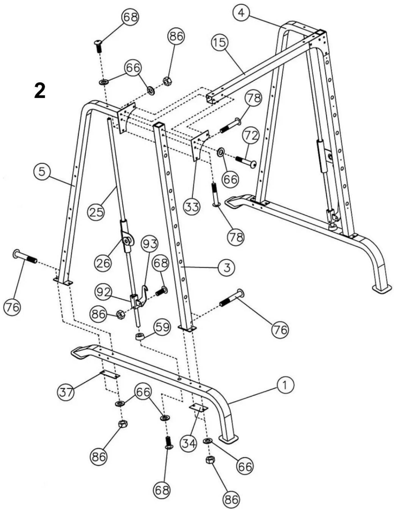
Step 2 (see diagram 2)
- Place the front vertical frame (3) against the base frame (1). Connect with screws (76), bracket (34), washers (66) and nuts (86). Do not tighten completely.
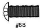
- Align the buffer (59) with the hole in the main frame. Pass the guide rod (25) through the buffer and fasten it with a screw (68) and washer (66).
- Place the lower safety frame (92) on the guide rod (25). Secure the safety hook (93) with the screw (68) and nut (86). Hook the hook onto the rear part of the vertical beam (3).
- Place the safety device (26) on the guide (25).
- Insert the guide rail (25) into the hole in the upper part of the right vertical frame (5). Align it with the front frame (3) – both at the top and bottom.
- Screw the guide rail (25) to the frame (5) with the screw (68) and washer (66).
- Screw the vertical frame (5) to the base frame using screws (76), brackets (37), washers (66) and nuts (86). Do not tighten too much.
- Connect the vertical frame (5) to the front beam (3) using the bracket (33), bolt (72) and washers (66). Secure the lower holes with a bolt (78), washers (66) and nuts (86).
- Repeat steps 1–8 for the other sides.
- Fit the front upper beam (15) to the vertical beams (3) and the triangular bracket (33). Fasten with bolts (78), washers (66) and nuts (86).
- Do not tighten the bolts yet.
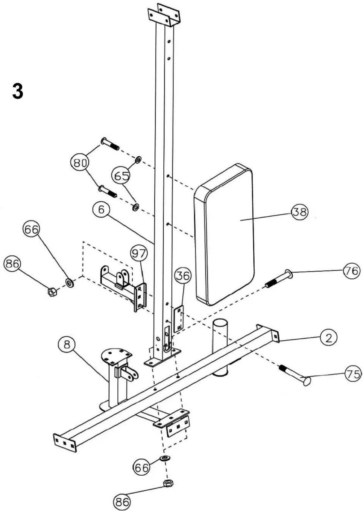
Step 3 (see diagram 3)
- Align the rear vertical beam (6) with the upper crossbar (2). Attach the guide (8) from below. Fasten with screws (75), bracket (36), washers (66) and nuts (86).
- Attach the pulley mechanism bracket (97) to the beam (6) - screws (75), bracket (36), washers (66), nuts (86).
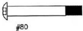
- Screw the backrest board (38) to the beam (6) with screws (80) and washers (65).
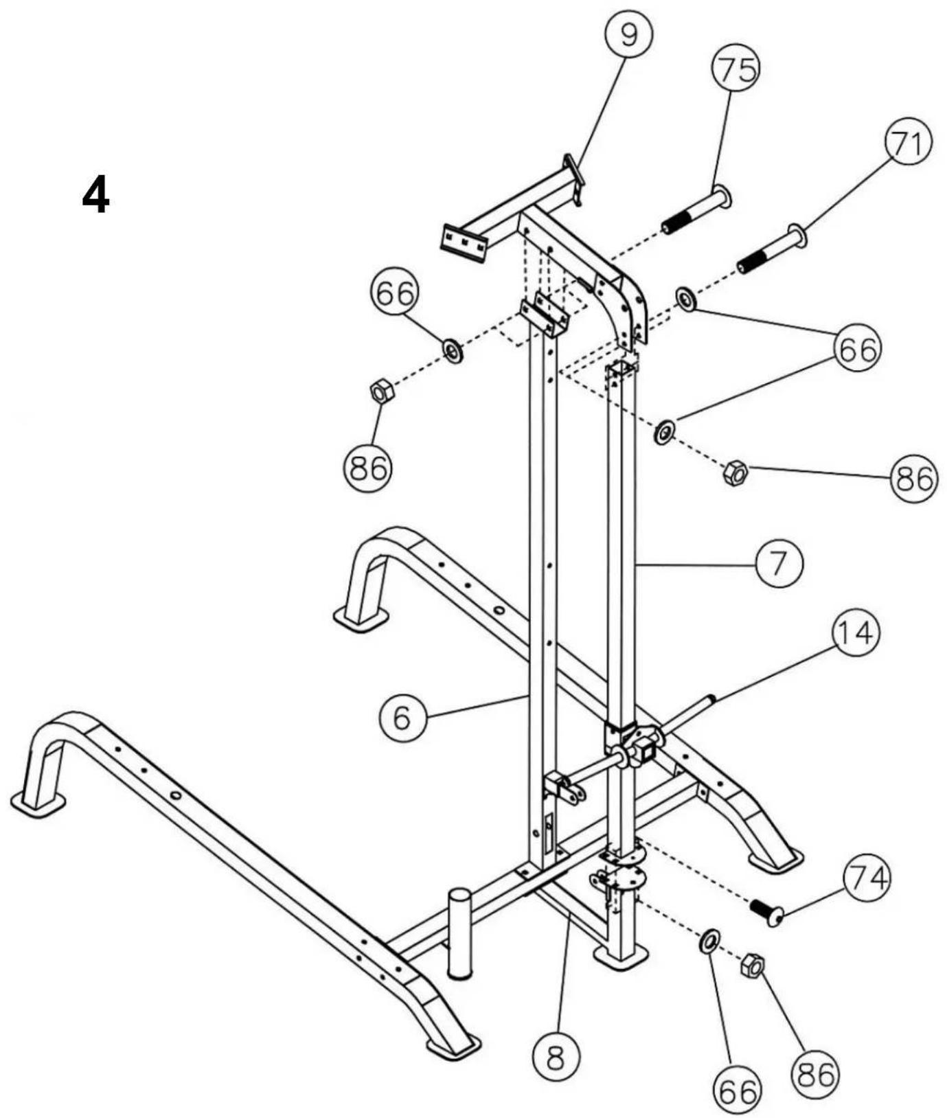
Step 4 (see diagram 4)
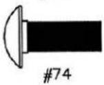
- Connect the crane post (7) to the base (8) - bolts (74), washers (66), nuts (86).
- Place part (14) onto the post (7). Then attach the rear upper frame (9) to the post (7) and beam (6).
- Align the holes. Screw the upper frame to the base (8) using screws (71), washers (66) and nuts (86). Do not tighten.
- Connect the upper frame to the lower beam (6) with screws (75), washers (66) and nuts (86).
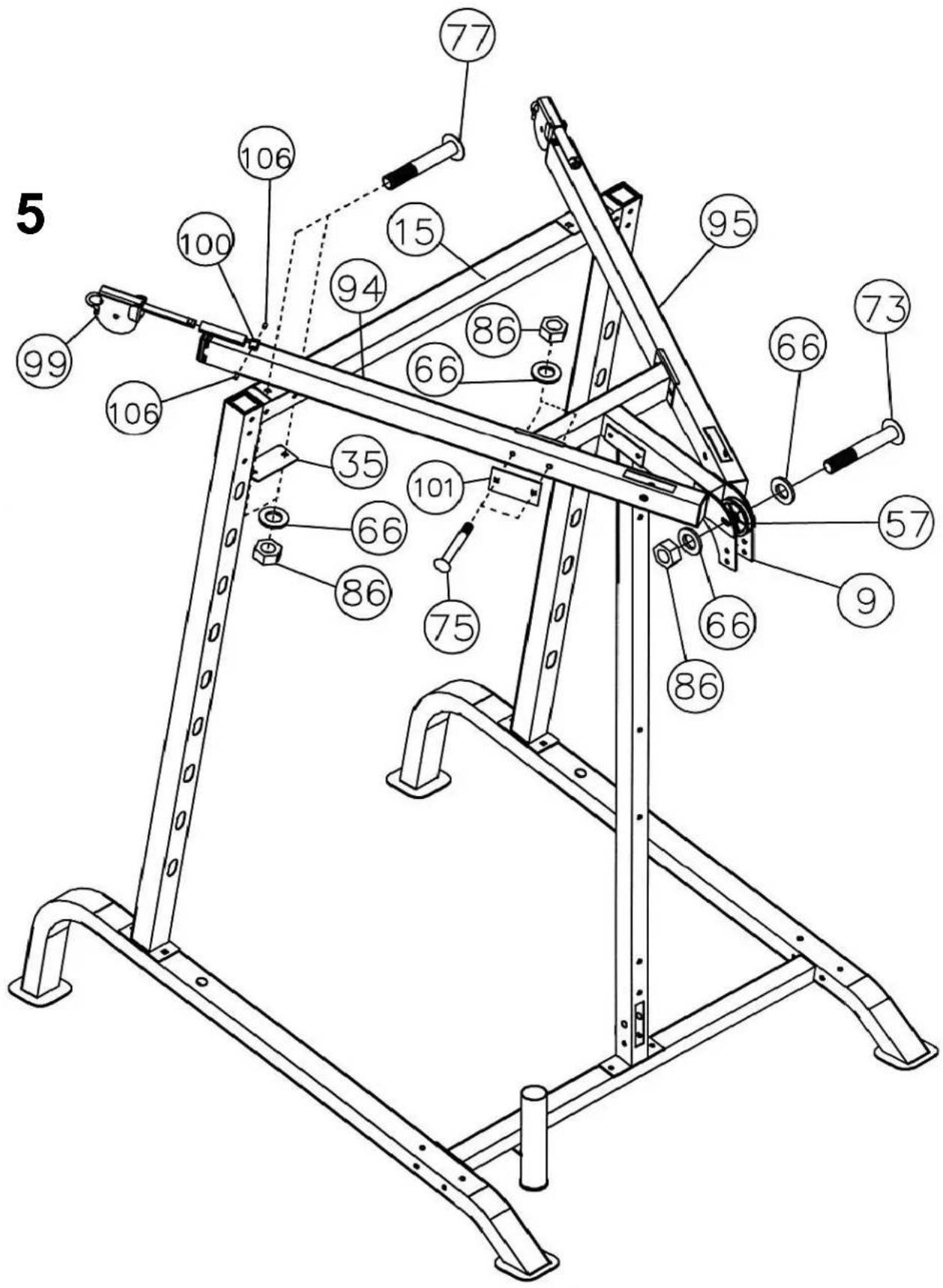
Step 5 (see diagram 5)
- Place the left upper frame (94) on the front beam (15). Fasten with screws (77), bracket (35), washers (66) and nuts (86).
- Connect the frame (94) to the rear upper frame - screws (75), bracket (101), washers (66), nuts (86).
- Insert the hinge (99) into the frame flange (94). Secure with the sleeve (100) and screws (106).
- Repeat for the right upper frame (95). Insert the disc (57) into the hole in the rear frame (9). Connect both upper frames to the rear frame – bolt (73), washers (66), nut (86).
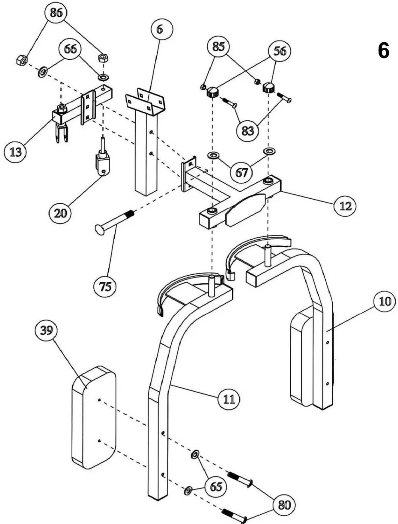
Step 6 (see diagram 6)
- Now tighten all previously installed bolts and nuts.
- Place the butterfly base (12) against the front of the beam (6). Attach the disc bracket (13) from the rear. Connect with screws (75), washers (66) and nuts (86).
- Place the right arm of the butterfly bracket (11) against the frame opening (12). Tighten with screws (80) and washers (65).
- Repeat for the other side.
- Insert the hinges (20) into the bracket (13). Connect with a washer (66) and nut (86). Do not tighten too much – the hinges must be movable.
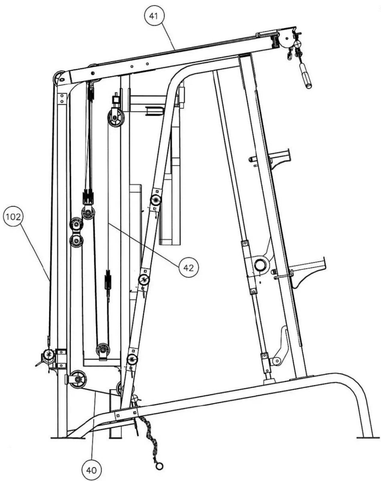
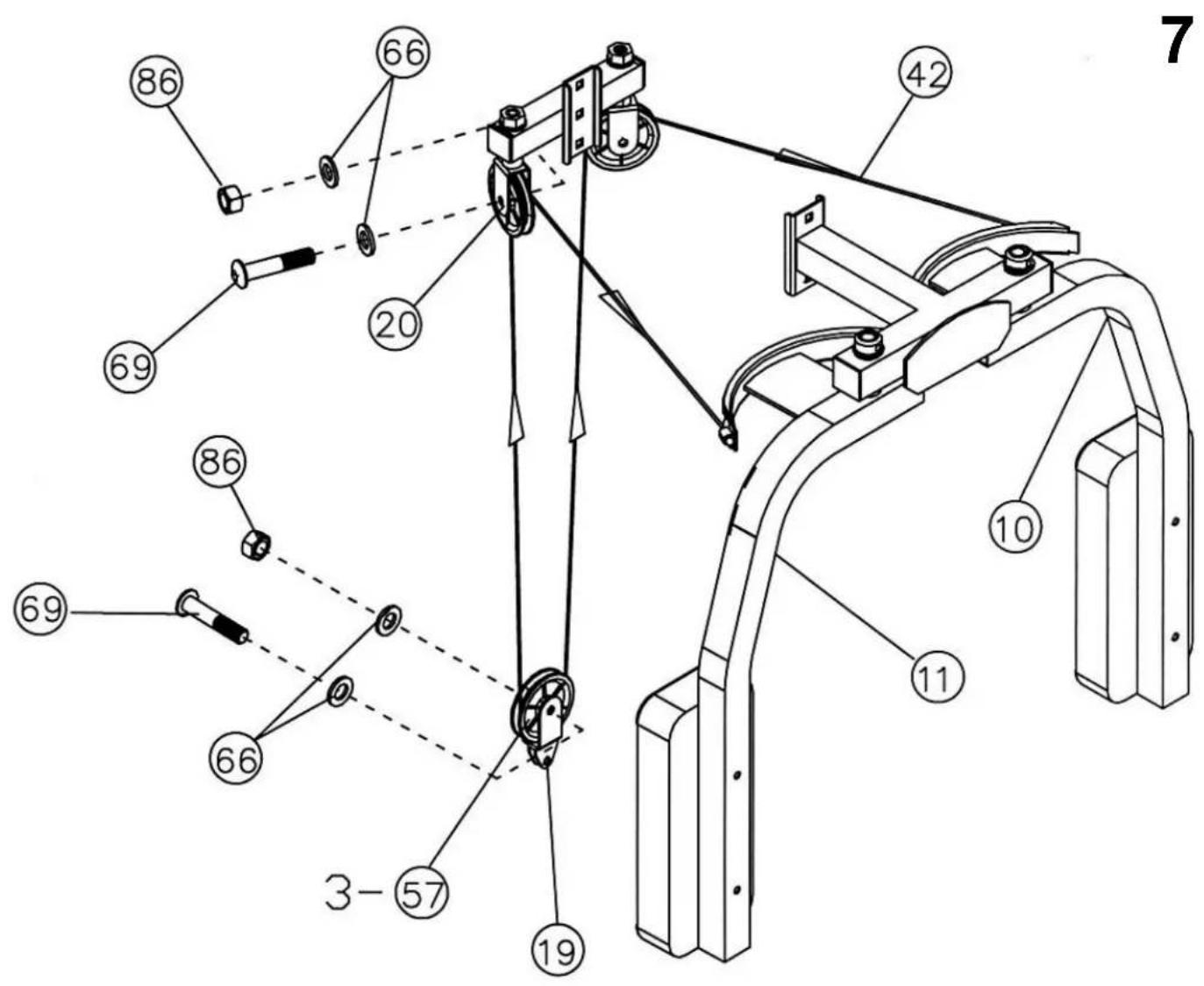
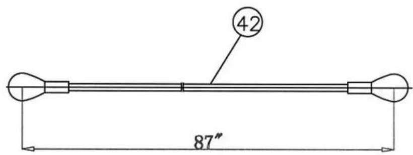
Step 7 (see diagram 7 and cable circuit diagram)
- Attach one end of the cable (42) to the latch on the right arm of the butterfly (11). Pull the cable through the right swivel (20).
- Install the pulley (57) in its housing - screw (69), washers (66), nuts (86).
- Run the cable around the pulley downwards. Attach the pulley housing (19) to the cable and repeat the pulley installation as in step 2. The pulley housing should hang freely.
- Run the cable around the hanging pulley, then upwards to the left swivel. Install the pulley in the bracket as in point 2.
- Dragg the cord around the pulley and attach it to the left arm of the butterfly (10).
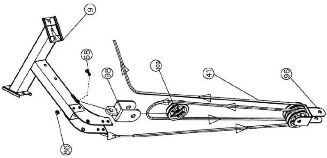
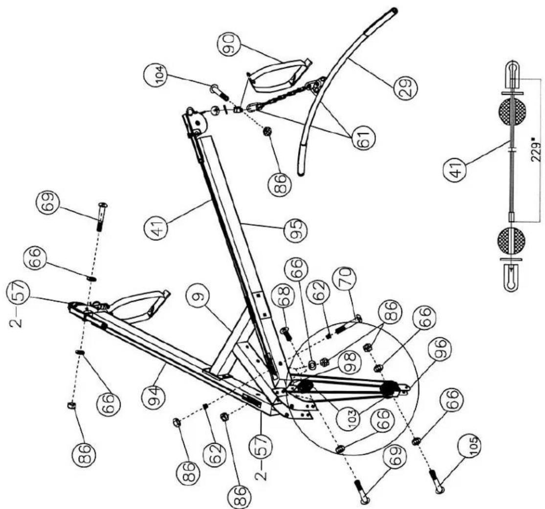
Step 8 (see diagram 8)
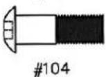
- Unscrew the screw (104) and nut (86) from the U-shaped connector on the cable (41). Remove the connector, large washer and lock plug.
- Pass the end of the cable through the left swivel (99). Install the pulley (57) in the bracket – screw (69), washers (66), nuts (86). Pull the cable through the pulley towards the rear of the unit.
- Route the cable along the left upper frame (94) and thread it through the hole at its end.
- Fit the pulley into the hole - screw (70), sleeve (62), nut (86). Pull the cable around the pulley and direct it downwards.
- Attach two small pulleys (103) to the triple bracket (96) - screw (105), washers (66), nut (86).
- Run the cable around the pulley, then up to the bracket under the top rail (9). Fit the small pulley bracket (98) to the underside of the rail – screw (68), washers (66), nut (86). Insert the pulley.
- Run the cable around the pulley and down to the triple bracket. Then around the front pulley and up to the hole in the right upper frame (95). Allow the bracket to hang down.
- Fit the pulley into the hole. Route the cable above the pulley along the right-hand frame (95), through the cable cover to the pulley housing. Fit the pulley.
- Reinstall the lock plug, large washer and U-shaped connector. Tighten with the screw (104) and nut (86).
- Connect the handle (90) to the ends of the cable with a latch (61).
- To install the cross handle, remove one handle (90), attach it with a short chain (63) and two latches (61).
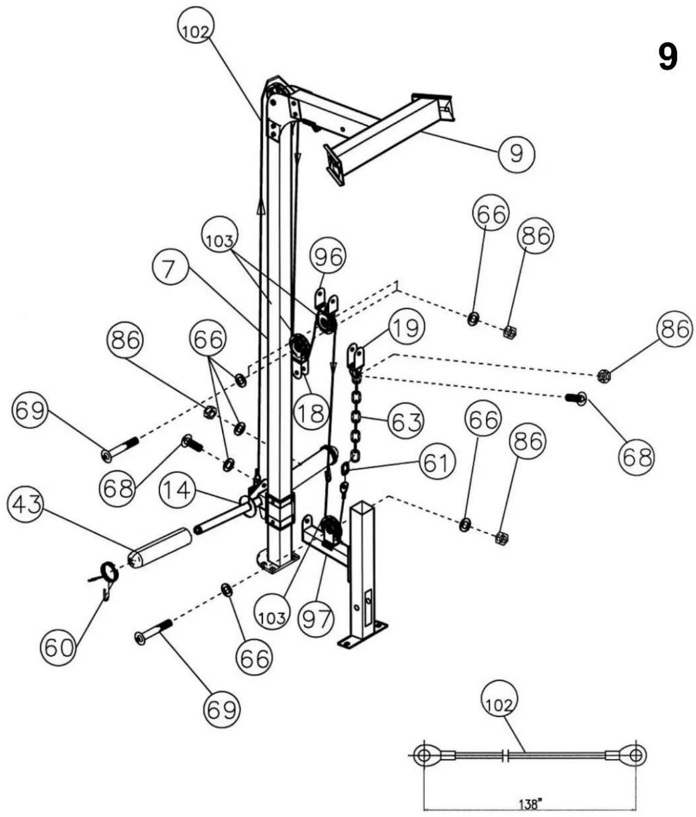
Step 9 (see diagram 9)
- Insert the end of the cable (102) into the hole in the crane post (14). Secure with a bolt (68), washer (66) and nut (86).
- Guide the cable upwards to the pulley on the upper frame (9) (installed in step 5).
- Pull the cable around the pulley and direct it downwards. Fit the small pulley (103) into the double bracket (18).
- Guide the cable around the pulley to the triple bracket (96) from step 8.
- Fit the small pulley into the bracket. Guide the cable around it and down to the open bracket on the support (97).
- Fit the small pulley into the bracket. Run the cable around it and upwards.
- Connect the cable to the short chain (63) with a snap hook (61). Connect the chain to the pulley bracket (19) from step 7 – screw (68), washers (66), nut (86).
- Adjust the tension of the cable by adjusting the length of the chain (63).
- Fit the sleeves (43) and spring clips (60) onto the crane post (14).
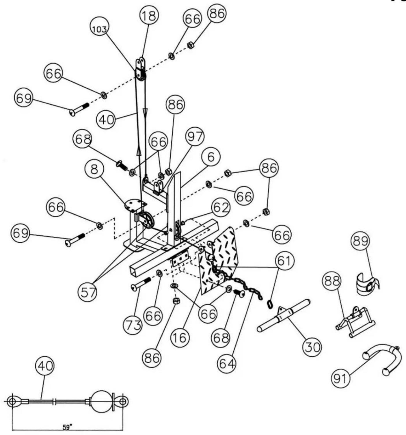
Step 10 (see diagram 10)
- Place the lower cable (40) on the pulley (57). Install the pulley in the lower hole of the rear beam (6) together with the footrest (16) – bolt (73), washers (66), nut (86). Screw the support to the crossbar (2) – bolts (68), 4 washers (66), nut (86).
- Route the cable below the pulley to the bracket on part (8).
- Install the pulley in the bracket. Route the cable around it and up to the double bracket (18) from step 9.
- Fit the small pulley (103) into the bracket. Run the cable around the pulley and down to the bracket on the support (97). Secure the end of the cable – screw (68), washers (66), nut (86).
- Connect the rod (30) to the long chain (64) with the latch (61). Connect the chain to the cable – latch (61).
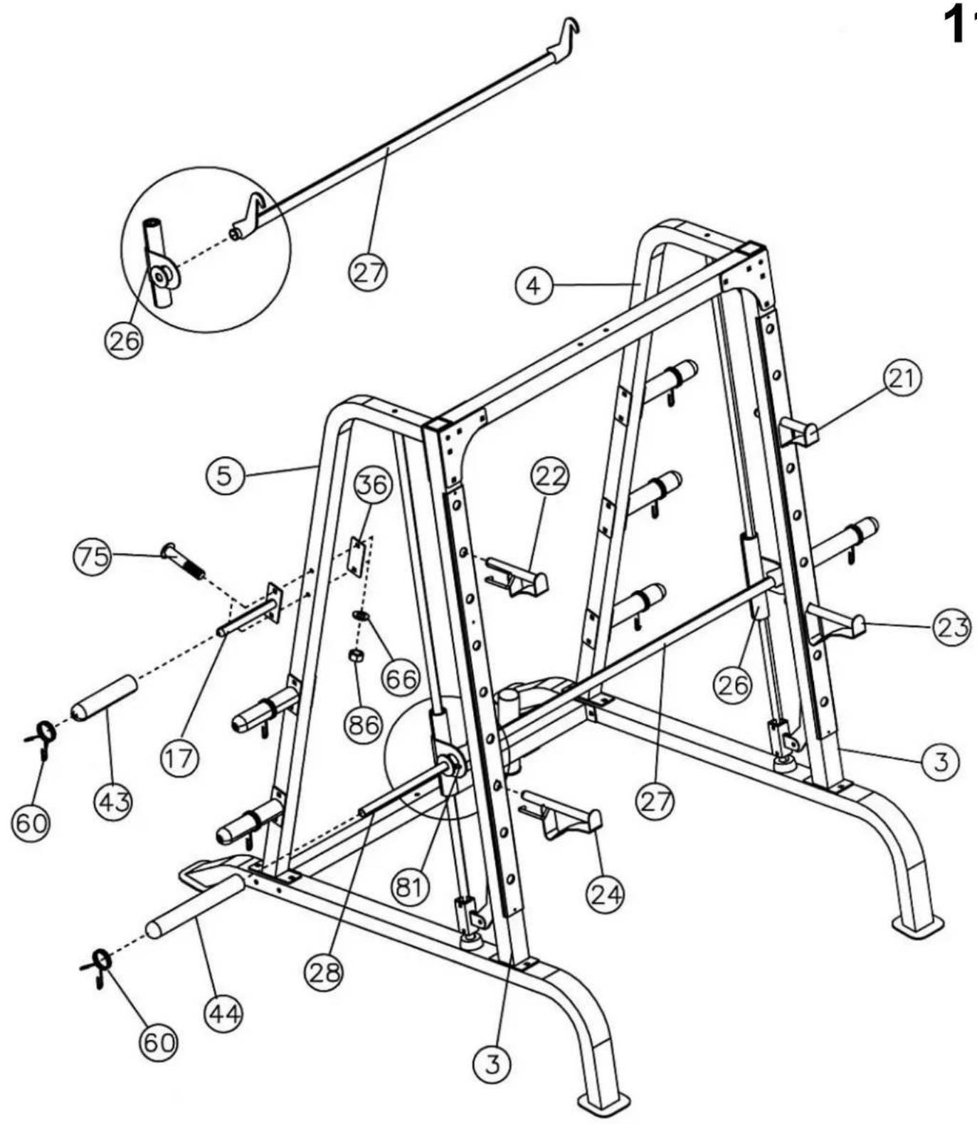
Step 11 (see diagram 11)
- Suggestion: you will need the help of another person. Place the sleeve (27) between the parts (26). Align the holes and insert the bar (28) into the safety mechanism frame (26). Secure the bar at the ends of the mechanism with a screw (81).
- Bend the sleeve hooks (27) backwards and hook them into the holes in the front frame (3). Place the Olympic sleeves (44) on the ends of the barbell and secure them with spring clips (60).
- Attach six posts (17) to the vertical frames (2 and 5) – bolts (75), bracket (36), washers (66), nuts (86).
- Place six Olympic sleeves (43) on the posts (17) and secure with clips (60).
- Insert the barbell holders (21 and 22) and latches (23 and 24) into the selected holes in the front frame (3).
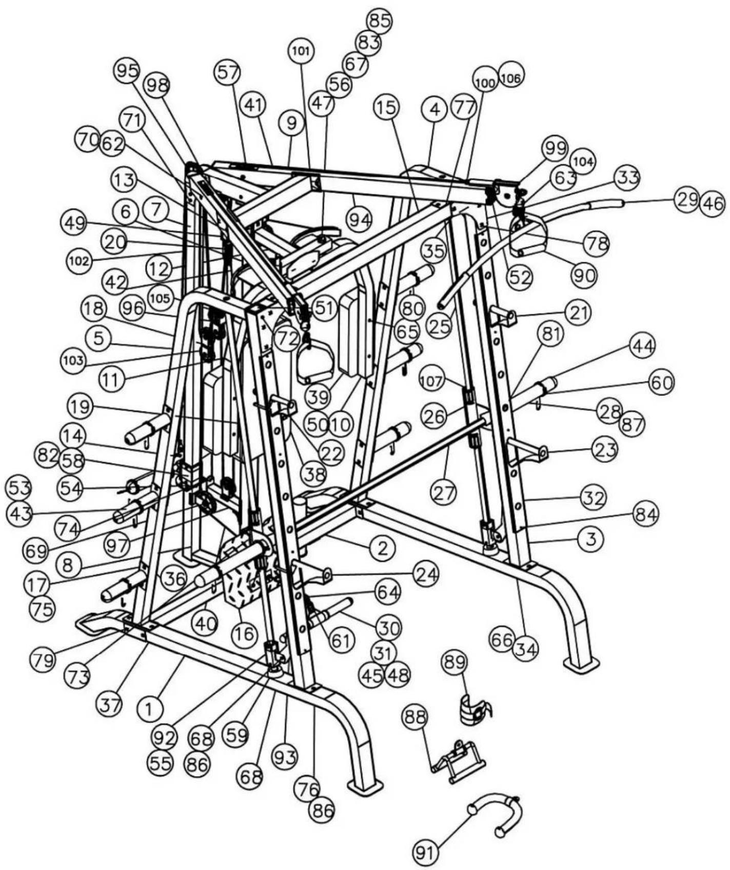
PARTS LIST:
| No. | Part name | Quantity | No | Part name | Quantity |
| 1 | Lower frame | 2 | 56 | Locking ring | 2 |
| 2 | Cross bracket | 1 | 57 | Block | 10 |
| 3 | Front vertical structural element | 2 | 58 | Rubber buffer ∅ 1 3/4" | 1 |
| 4 | Left vertical structural element | 1 | 59 | Rubber buffer ∅ 2 1/2" | 2 |
| 5 | Right vertical structural element | 1 | 60 | Spring latch | 10 |
| 6 | Rear vertical structural elements | 1 | 61 | C-clip | 5 |
| 7 | Weight guide | 1 | 62 | Pulley sleeve | 6 |
| 8 | Weight guide base | 1 | 63 | Short chain | 2 |
| 9 | Rear upper part of the frame | 1 | 64 | Long chain ∅ | 1 |
| 10 | Left butterfly mechanism | 1 | 65 | 5/8" washer | 6 |
| 11 | Right butterfly mechanism | 1 | 66 | Washer ∅ 3/4" | 100 |
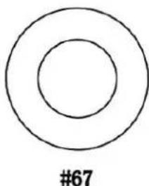
| 12 | Butterfly mechanism base | 1 | 67 | Washer ∅ 1 1/2" | 2 |
| 13 | Butterfly block mounting | 1 | 68 | M10 x 1" Allen screw | 12 |
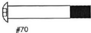
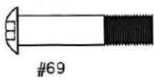
| 14 | Sliding weight guide | 1 | 69 | M10 x 1 3/4" Allen screw | 11 |
| 15 | Front upper beam | 1 | 70 | M10 x 2 1/2" Allen screw | 2 |
| 16 | Footrest plate | 1 | 71 | M10 x 3" Allen screw | 2 |
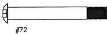
| 17 | Weight post | 6 | 72 | M10 x 3 1/8" Allen screw | 2 |
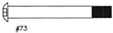
| 18 | Double hanging block handle | 1 | 73 | M10 x 3 3/8" Allen screw | 2 |
| 19 | Single hanging block bracket | 1 | 74 | M10 x 1" mushroom head screw | 4 |
| 20 | Rotating pulley bracket | 2 | 75 | Mushroom head screw M10 x 2 3/4" | 22 |
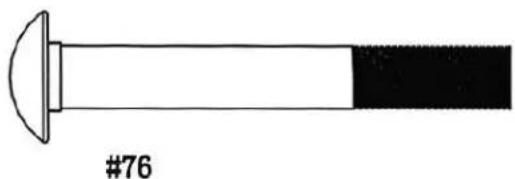
| 21 | Left neck holder | 1 | 76 | M10 x 3" mushroom head screw | 10 |
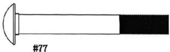
| 22 | Right-hand neck clamp | 1 | 77 | M10 x 3 1/8" mushroom head screw | 4 |
| 23 | Left safety lock | 1 | 78 | M10 x 3 3/8" mushroom head screw | 8 |
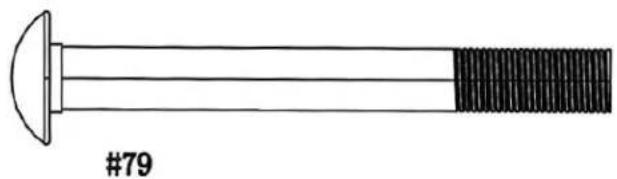
| 24 | Right safety lock | 1 | 79 | Mushroom head screw M10 x 3 1/2" | 4 |
| 25 | Guide rail (guide rod) | 2 | 80 | M8 x 2 1/2" Allen screw | 6 |
| 26 | Safety retaining frame | 2 | 81 | M8 x 3/8" Allen screw | 2 |
| 27 | Lifting sleeve | 1 | 82 | Cross screw M6 x 5/8" | 1 |
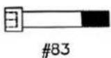
| 28 | Weight bar | 1 | 83 | M6 x 1 1/4" Allen screw | 2 |
| 29 | Back exercise bar (Lat Bar) | 1 | 84 | Screw for chrome panel | 8 |
| 30 | Shiver Bar | 1 | 85 | M6 self-locking nut (Aircraft Nut) | 2 |
| 31 | Biceps curl handle | 1 | 86 | M10 self-locking nut (Aircraft Nut) | 82 |
| 32 | Chrome panel | 2 | 87 | End cap ∅ 1" | 6 |
| 33 | Triangular bracket | 2 | 88 | V-shaped bar (V Bar) | 1 |
| 34 | Bracket 5 1/8" x 2 3/4" | 2 | 89 | Ankle strap | 1 |
| 35 | Bracket 5 1/8" x 2 3/8" | 2 | 90 | Single handle bar | 2 |
| 36 | Bracket 4 3/4" x 2" | 9 | 91 | Triceps rope | 1 |
| 37 | 6 1/4" x 2" bracket | 2 | 92 | Lower safety retaining frame | 2 |
| 38 | Backrest (board) | 1 | 93 | Safety hook | 2 |
| 39 | Butterfly arm cushion | 2 | 94 | Left upper frame | 1 |
| 40 | Lower cable 59" | 1 | 95 | Right upper frame | 1 |
| 41 | Upper line 229" | 1 | 96 | Triple bracket for hanging pulley | 1 |
| 42 | Butterfly 87" rope | 1 | 97 | Pulley support frame | 1 |
| 43 | Olympic sleeve | 8 | 98 | Small single pulley handle | 1 |
| 44 | Long Olympic sleeve | 2 | 99 | Cross-Over pulley swivel | 2 |
| 45 | Biceps curl bar handle (Curl Bar handle) | 2 | 100 | Bushing ∅ 7/8" x ∅ 5/8" | 2 |
| 46 | Lat bar handle | 2 | 101 | Bracket 4 3/4" x 2 3/4" | 2 |
| 47 | Bushing ∅ 1" x 3 1/8" | 2 | 102 | Weight post guide cable 138" | 1 |
| 48 | Bushing ∅ 1 1/2" x 1" | 2 | 103 | Small pulley | 7 |
| 49 | Square cap 1 1/2" | 2 | 104 | M10 x 1 1/8" Allen screw | 2 |
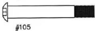
| 50 | Square cap 1 3/4" | 7 | 105 | M10 x 2 3/4" Allen screw | 1 |
| 51 | Square cap 2 3/8" | 2 | 106 | M6 x 1/4" Allen screw | 4 |
| 52 | Cap 2 3/4" x 2" | 2 | 107 | Linear bearing | 4 |
| 53 | Tapered cap ∅ 1" | 12 | 108 | Linear bearing sleeve | 4 |
| 54 | Bushing 2 3/8" x 2" | 2 | 109 | M6 x 1/4" cross screw | 4 |
| 55 | Sliding sleeve | 4 |
INSTALLATION STEPS:
Step 1 (see diagram A)
- Place the main frame (1) against the front and rear stabilisers (2 and 3). Connect the components using screws (36) and washers
(42). Then insert the pin (23) into the hole located under the main frame. - Place the sliding lock (8) on the adjustment bar (9). Align the holes and insert the pin (23) to stabilise the position of the lock.
- Connect the adjustment beam (9) to the main frame using the bolt (35), washer (42) and nut (44).
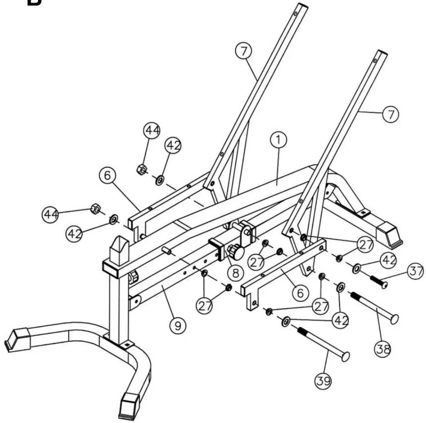
Step 2 (see diagram B)
- Insert the four bushings (27) into the frame bracket (6).
- Place the backrest bracket (7) against the rear side of the frame bracket (6). Align the holes and connect them with a screw (37) and washer (42). Repeat for the other side.
- Insert two sleeves into the sliding lock (8) and then into the backrest bracket (7). Align the holes and connect them with a screw (38), washers (42) and a nut (44). Leave the screws slightly loose.
- Insert the sleeves into the main frame (1). Loosen the lock knob (8). The sliding lock should move freely along the adjustment bar (9). Place the two brackets (6) on both ends of the main frame and fasten them with screws (39), washers (42) and nuts (44). Use the knob to lock the backrest in place.
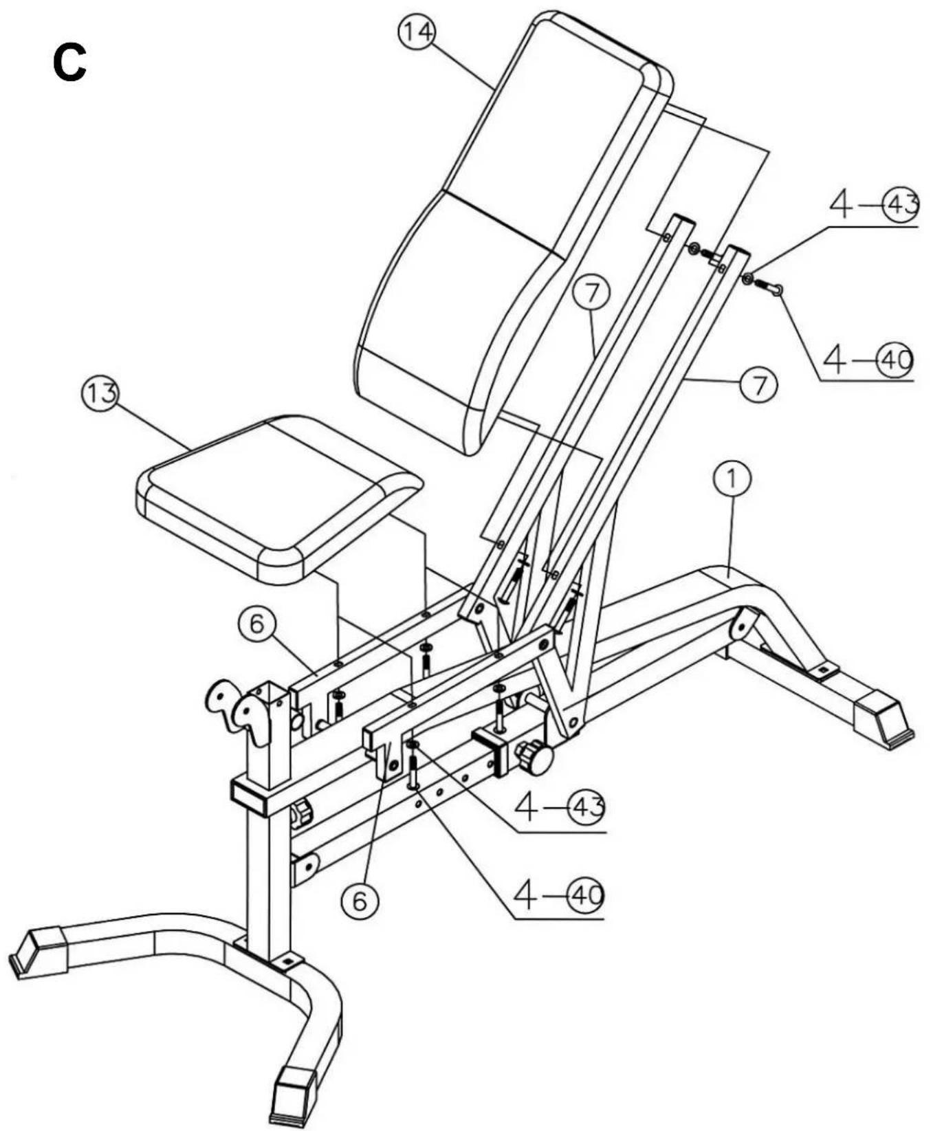
Step 3 (see diagram C)
- Place the backrest (14) on the bracket (7) and screw it in place using screws (40) and washers (43).
- Place the seat (13) on the bracket (6) and screw it in place using screws (40) and washers (43).
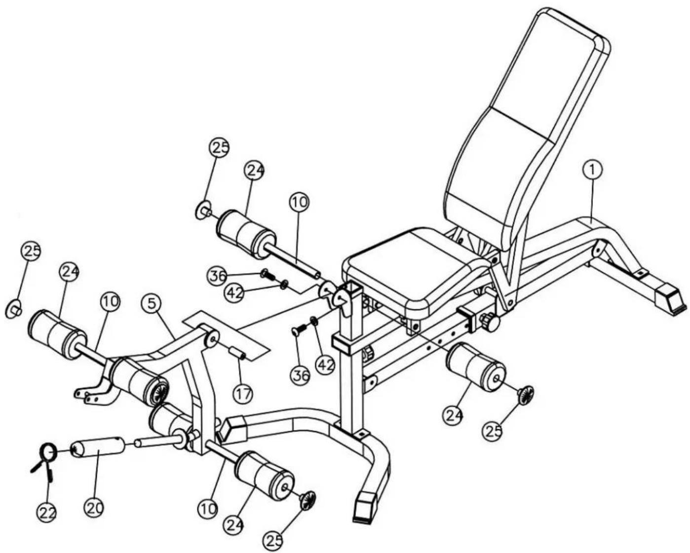
Step 4 (see diagram D)
- Place the leg trainer (5) on the main frame (1), sliding it into the bracket hole. Secure the assembly with the axle (17), screws (36) and washers (42).
- Insert the tube (10) halfway into the opening in the main frame (1), then into the leg trainer frame (5). Attach the foam rollers (24) and secure them with the caps (25).
- Slide the Olympic sleeve (20) onto the post at the base of the leg trainer and secure it with the spring clip (20).
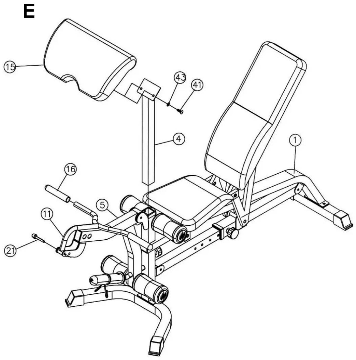
Step 5 (see diagram E)
- Connect the arm cushion (15) to the frame (4). Fasten the components with screws (41) and washers (43). Insert the frame (4) into the front opening of the main frame (1). Use the knob to adjust the position of the cushion.
- Fit the handle (11) into the hole in the leg trainer bracket (5). Lock it in place with the pin (21).
- Remove the pin and handle (11) during leg training.
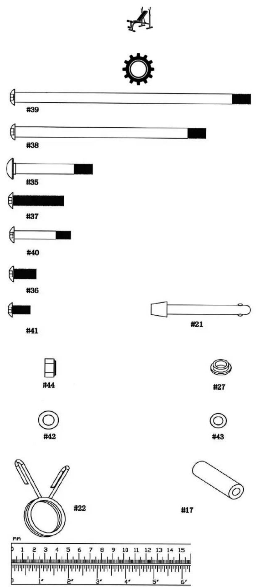
PARTS TABLE
| No. | Part name | Quantity | No | Part name | Quantity |
| 1 | Main frame | 1 | 2 | Lock knob | 2 |
| 2 | Front stabiliser | 1 | 24 | Foam roller | 6 |
| 3 | Rear stabiliser | 1 | 25 | Foam roller cap | 6 |
| 4 | Biceps exercise rack | 1 | 26 | Bushing ∅ 1" x 3/4" | 2 |
| 5 | Leg trainer | 1 | 27 | Bushing | 16 |
| 6 | Seat bracket | 2 | 28 | Cap 3 1/8" x 1 5/8" | 1 |
| 7 | Backrest bracket | 2 | 29 | Conical cap ∅ 1" | 1 |
| 8 | Sliding lock | 1 | 30 | End cap ∅ 1" | 1 |
| 9 | Tilt adjustment bar | 1 | 31 | End cap 1 5/8" x 2 3/8" | 2 |
| 10 | Foam tube | 3 | 32 | End cap 1 5/8" x 3/4" | 12 |
| 11 | Biceps exercise handle | 1 | 33 | 2" sliding lock bushing | 3 |
| 12 | Instructions | 1 | 34 | Stabiliser cap | 4 |
| 13 | Seat cushion | 1 | 35 | M10 x 2 1/2" screw (square head) | 2 |
| 14 | Backrest | 1 | 36 | M10 x 3/4" Allen screw | 6 |
| 15 | Biceps exercise pad | 1 | 37 | M10 x 1 3/4" Allen screw | 2 |
| 16 | Biceps curl bar | 2 | 38 | M10 x 6 3/4" Allen screw | 1 |
| 17 | Axle | 1 | 39 | M10 x 8 1/4" Allen screw | 1 |
| 18 | Bushing ∅ 2 3/8" | 2 | 40 | M8 x 2" Allen screw | 8 |
| 19 | Tool | 2 | 41 | M8 x 5/8" Allen screw | 2 |
| 20 | Olympic sleeve | 1 | 42 | Washer ∅ 3/4" | 14 |
| 21 | Locking pin | 1 | 43 | Washer ∅ 5/8" | 10 |
| 22 | Spring clamp | 1 | 44 | M10 wing nut | 4 |
UWAGI DOTYCZĄCE BEZPIECZEŃSTWA
-
The Seller, on behalf of the Guarantor, provides a guarantee in the territory of the Republic of Poland for a period of 24 months from the date of sale.
-
The guarantee will be honoured by the shop or service centre upon presentation by the customer:
- a legibly and correctly completed warranty card with the sales stamp and the seller's signature,
- a valid proof of purchase of the equipment with the date of sale / receipt, the goods claimed.
-
Any defects and damage discovered during the warranty period will be repaired free of charge within a maximum of 21 days from the date of delivery of the goods to the service.
-
In the case of the necessity to import parts, the repair period may be extended by the time necessary for their import, but not longer than 90 days.
-
The warranty does not cover:
- mechanical damage and defects caused by them,
- damages and defects resulting from improper use and storage,
- improper assembly and maintenance,
- damage and wear of components such as cables, straps, rubber parts, pedals, sponge grips, wheels, bearings, etc.
- The warranty is void in the event of:
- expiry date,
- self-repair,
- failure to observe the rules of correct operation.
-
Product returned for repair should be complete and clean. In the case of defects the service has the right to refuse acceptance for repair. If the product is delivered dirty, the service centre may refuse to accept it or clean it at the customer's expense with his written consent.
-
The warranty does not cover installation and maintenance work, which, according to the user manual, must be carried out by the user himself.
-
The guarantor also informs that it provides post-warranty service.
-
The goods should be protected for shipping.
-
In order to make use of the warranty, please follow the procedure on the website: https://serwis.abisal.pl/.
In case of non-conformity of the sold thing with the contract, the buyer is entitled by law to legal remedies from and at the expense of the seller. The guarantee does not affect such remedies.
THE EQUIPMENT IS NOT INTENDED FOR REHABILITATION AND THERAPY
NOTES ON THE COURSE OF REPAIRS
| Item | Date of notification | Date of provision | Course of repairs | Signature of the recipient (shop, owner) |
KARTA GWARANCYJNA
CONDITIONS DE GARANTIE:
HMS-FITNESS.COM

HMS®
IMPORTER: ABISAL SP. Z O.O., ul. Pyskowicka 17, 41-807 Zabrze, Polska
DISTRIBUTOR: ABISTORE SPORT S.R.O, U Cihelny 230/3, 74801 Hlučín, Česká Republika

- SAFETY NOTES
- WARNING
- TECHNICAL DATA
- MAINTENANCE
- INSTALLATION STEPS:
- Step 1 (see diagram 1)
- Step 2 (see diagram 2)
- Step 3 (see diagram 3)
- Step 4 (see diagram 4)
- Step 5 (see diagram 5)
- Step 6 (see diagram 6)
- Step 7 (see diagram 7 and cable circuit diagram)
- Step 8 (see diagram 8)
- Step 9 (see diagram 9)
- Step 10 (see diagram 10)
- Step 11 (see diagram 11)
- Step 1 (see diagram A)
- Step 2 (see diagram B)
- Step 3 (see diagram C)
- Step 4 (see diagram D)
- Step 5 (see diagram E)
- UWAGI DOTYCZĄCE BEZPIECZEŃSTWA
- THE EQUIPMENT IS NOT INTENDED FOR REHABILITATION AND THERAPY
- KARTA GWARANCYJNA
- CONDITIONS DE GARANTIE:
Brand : HMS Premium
Model : TYTAN101
Category : Fitness Equipment