PROS 680NV - Sander Mirka - Free user manual and instructions
Find the device manual for free PROS 680NV Mirka in PDF.

| Product Type | Pneumatic Random Orbital Sander |
| Brand | Mirka |
| Model | PROS 680NV |
| Eccentricity | 8 mm |
| Pad Diameter | 150 mm (6") |
| Free Speed | 12 000 tr/min |
| Power Consumption | 270 W |
| Air Consumption | 485 l/min |
| Recommended Air Pressure | 6.2 bar (90 psig) |
| Dust Extraction Type | Central (vacuum connection) |
| Sound Level | 74 dB(A) |
| Vibration Level | 3.4 m/s² (uncertainty 0.8 m/s²) |
| Net Weight | 0.95 kg |
| Dimensions (L x H) | 229 x 102 mm |
| Power Supply | Compressed air (max pressure 6.2 bar) |
| Compatible Materials | Metal, wood, stone, plastic |
| Pad Brake System | Yes, adjustable via washers |
| Lubrication | Recommended: Würth oil no. 08930505 or via FRL |
| Maintenance | Silencer cleaning, pad and brake replacement |
| Spare Parts | Kit A (bearings), Kit F (vanes and rotor), Mirka pads |
Frequently Asked Questions - PROS 680NV Mirka
User questions about PROS 680NV Mirka
0 question about this device. Answer the ones you know or ask your own.
Ask a new question about this device
Download the instructions for your Sander in PDF format for free! Find your manual PROS 680NV - Mirka and take your electronic device back in hand. On this page are published all the documents necessary for the use of your device. PROS 680NV by Mirka.
USER MANUAL PROS 680NV Mirka
natural_image
Black and white MIRKA PRO5 6801 electric power grinder on a circular base (no visible text or symbols on the device body)
natural_image
Stylized illustration of a bulldog in aggressive posture (no text or symbols)Mirka® PROS
150mm(6"), 125mm(5")
Operating instructions (original)......56en
People's Republic of China
zh 操作说明....227
United Kingdom
en|UK Operating instructions....234
Exploded view
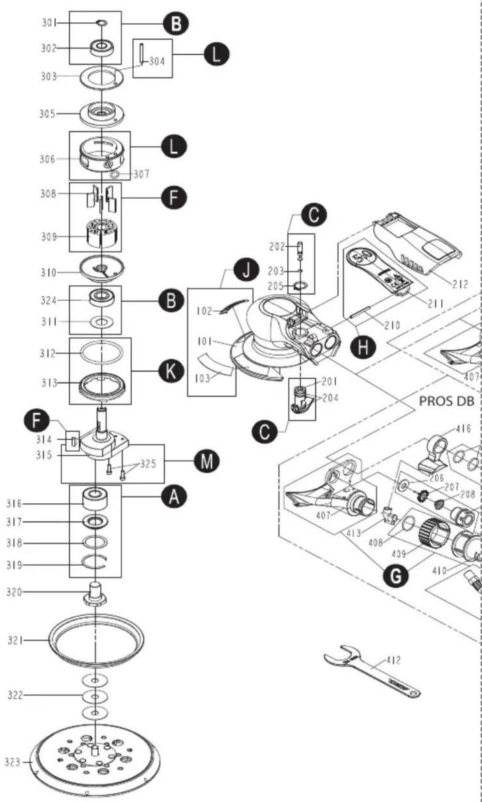
Parts list -kits
| Part NoQuantity | ||||
| ABearing kit (loose parts)MIE6536211 | ||||
| MPP03161Bearing316 | ||||
| MPP03171Rubber Seal317 | ||||
| MPP0318opt.Washer (Optional | ||||
| MPP03191Retaining Ring319 | ||||
| 8995690141 | A+320Spindle Bearing kit (pre-assembled) | |||
| MPP03161Bearing316 | ||||
| MPP03171Rubber Seal317 | ||||
| MPP0318opt.Washer (Optional | ||||
| MPP03191Retaining Ring319 | ||||
| MPB03201Spindle | ||||
| 8995690021 | Endplate Bearing kit | B | MPP9002 | |
| MPP03011Retaining Ring301 | ||||
| MPP03021Bearing302 | ||||
| MPB03111Dust Seal | ||||
| MPP03241Bearing324 | ||||
| 8995690031 | Speed Valve kit | C | MPP9003 | |
| MPP02011Regulator Unit201 | ||||
| MPB02021Valve Stem | ||||
| MPB02031O-Ring | ||||
| MPB02042O-Ring | ||||
| MPP02051Retaining Ring205 | ||||
| 8995690041 | Muffler kit 12000 rpm | D | MPP9004 | |
| MPB04041Nozzle | ||||
| MPB04051Muffler | ||||
| MPB04061Muffler CAP | ||||
| MPB04221O-Ring | ||||
| MPB043231Powder Metal Silenc | ||||
| 8995690051 | Air Inlet kit | E | MPP9005 | |
| MPB08061Seal | ||||
| MPB07071Tip Valve | ||||
| MPB08081Valve Spring | ||||
| MPB08091Inlet Connection | ||||
| 8995690061 | Rotor, Vanes and Key kit | F | MPP9006 | |
| MPB08085Vanes | ||||
| MPB08091Rotor | ||||
| MPB04141Rotor Key | ||||
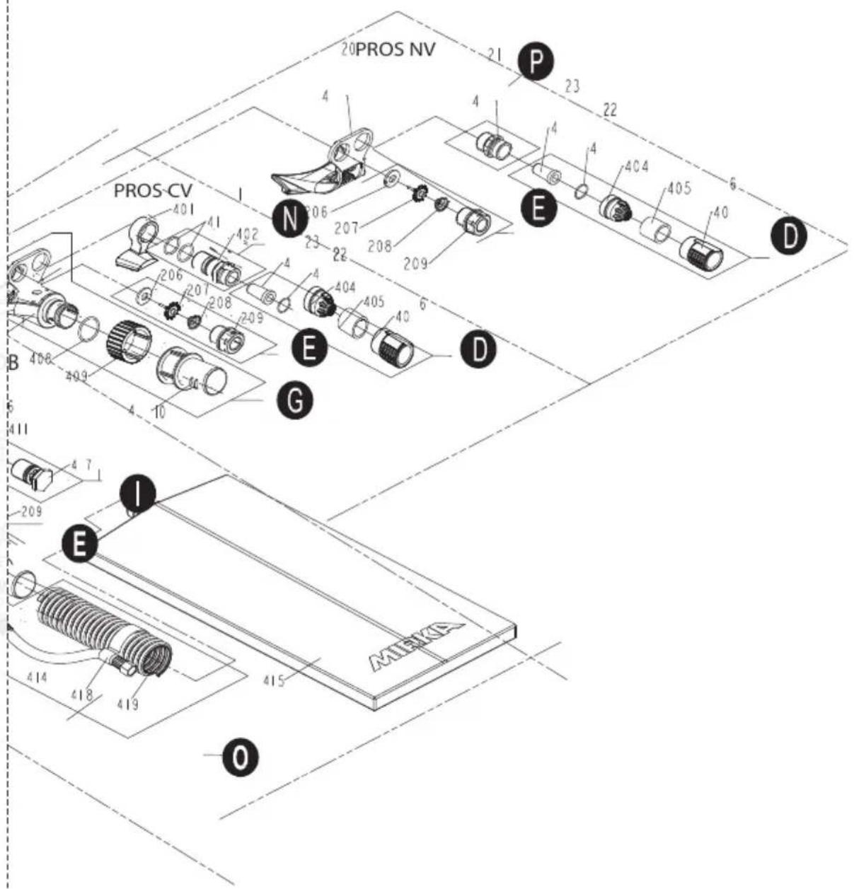
| 8995690071 | Exhaust and Swivel kit - PROS CV & DB | G | MPP9007 | |
| 407 | Vacuum Adapter - PROS CV & DB | 1 | ||
| MPP0407 | ||||
| MPB08081O-Ring | ||||
| MPB09091Swivel Grip | ||||
| MPB040101Swivel Connector | ||||
| 8995690151 | Lever kit 2,5 mm Orbit | H | MPP9015 | |
| MPB020101Spring Pin | ||||
| 211 | Lever 2,5 mm Orbit | 1 | ||
| MPP9008H Lever kit 5,0 mm | ||||
| MPP02101Spring Pin210 | ||||
| MPP02111Lever 5,0 mm Orbit2 | ||||
| MPP9009H Lever kit 8,0 mm | ||||
| MPP02101Spring Pin210 | ||||
| MPP02131Lever 8,0 mm Orbit2 | ||||
| MPP9022IRetainer and O-Ring | ||||
| MPP04112O-Ring411 | ||||
| MPP04171Exhaust Plug417 | ||||
| 8995690121 | Housing and Mark Plate kit | MPP9012J | ||
| MPR01011Housing | ||||
| MPR02021Mark Plate | ||||
| 103 | Model Sticker (550, 580, 625, 650 & 680) | 7 | MPP0103 | |
| 8995690111 | Lock Ring and O-Ring kit | MPP9011K | ||
| MPP03121O-Ring312 | ||||
| MPB03131Lock Ring | ||||
| 8995690131 | Cylinder, Spring Pin and O-Ring kit | MPP9013L | ||
| MPP03041Spring Pin304 | ||||
| MPB03061Cylinder | ||||
| MPP03071O-Ring307 | ||||
| 8995690251 | Shaft Balancer kit 2,5mm/125 mm - PROSMB9025M | |||
| 315 | Shaft Balancer 2,5 mm/ 100 g Pad | 1 | MPP0330 | |
| MPB03252Balance Screws | ||||
| 8995690161 | Shaft Balancer kit 5,0mm/125 mm - PROSMB9016M | |||
| 315 | Shaft Balancer 5,0 mm/ 100 g Pad | 1 | MPP0315 | |
| MPB03252Balance Screws | ||||
| 8995690211 | Shaft Balancer kit 8,0mm/125 mm - PROSMB9021M | |||
| 315 | Shaft Balancer 8,0 mm/ 100 g Pad | 1 | MPP0329 | |
| MPB03252Balance Screws | ||||
| 8995690171 | Shaft Balancer kit 2,5mm/150 mm - PROSMB9017M | |||
| 315 | Shaft Balancer 2,5 mm/ 130 g Pad | 1 | MPP0326 | |
| MPB03252Balance Screws | ||||
| 8995690181 | Shaft Balancer kit 5,0mm/150 mm - PROSMB9018M | |||
| 315 | Shaft Balancer 5,0 mm/ 130 g Pad | 1 | MPP0327 | |
| MPB03252Balance Screws | ||||
| 8995690191 | Shaft Balancer kit 8,0mm/150 mm - PROSMB9019M | |||
| 315 | Shaft Balancer 8,0 mm/ 130 g Pad | 1 | MPP0328 | |
| MPB03252Balance Screws | ||||
| 899569020MPP9020NMuffler Connectio | ||||
| MPR02021Muffler Connection | ||||
| MPP04112O-Ring411 | ||||
| 899569023MPP9023OHose Assembly ki | ||||
| MPR04141Hose Air Tube | ||||
| MPP04185Fastening Straps418 | ||||
| 419 | Hose 1.8 m for DB | 1 | MPP0419 | |
| 8995690241 | Muffler Connection kit - PROS NV | MPP9024P | ||
| MPR04211Muffler Connection | ||||
NOTE! Repairs done by non-authorized repairer will breach the Mirka warranty.
Electrical tools must be serviced by a qualified repair person and in accordance with national requirements.
Parts list – spareparts & accessories
| Part NoQuantity | ||||||
| MPP01011JHousing101 | ||||||
| MPP01021JMark Plate102 | ||||||
| 103 | Model Sticker (550, 580, 625, 650 & 680) | J | 7 | MPP0103 | ||
| MPP02011CRegulator Unit201 | ||||||
| MPP02021CValve Stem202 | ||||||
| MPP02031CO-Ring203 | ||||||
| MPP02042CO-Ring204 | ||||||
| MPP02051CRetaining Ring205 | ||||||
| 206 | Seal | MPP02061E | ||||
| 207 | Tip Valve | MPP02071E | ||||
| 208 | Valve Spring | MPP02081E | ||||
| 209 | Inlet Connection | MPP02091E | ||||
| 210 | Spring Pin | MPP02101H | ||||
| 211 | Lever 5,0 mm Orbit | H | 1 | MPP0211 | ||
| 211 | Lever 8,0 mm Orbit | H | 1 | MPP0213 | ||
| 211 | Lever 2,5 mm Orbit | H | 1 | MPP0214 | ||
| 8995602121 | 212 | Cover | 1 | MPP0212 | ||
| Retaining Ring301 | MPP03011B | |||||
| 302 | Bearing | MPP03021B | ||||
| 8995603031 | 303 | Front Ring | 1 | MPP0303 | ||
| 304 | Spring Pin | MPP03041L | ||||
| 8995603051 | 305 | Front Bearing Plate | 1 | MPP0305 | ||
| 306 | Cylinder | MPP03061L | ||||
| 8995603071 | 307 | O-Ring 10/pack | L | 1 | MPP0307 | |
| 308 | Vanes | MPP03085F | ||||
| 309 | Rotor | MPP03091F | ||||
| 8995603101 | 310 | Rear End Plate | 1 | MPP0310 | ||
| 311 | Dust Seal | MPP03111B | ||||
| O-Ring312 | MPP03121K | |||||
| 313 | Lock Ring | MPP03131K | ||||
| 314 | Rotor Key | MPP03141F | ||||
| 315 | Shaft Balancer 2,5 mm/ 100 g Pad | M | 1 | MPP0330 | ||
| 315 | Shaft Balancer 5,0 mm/ 100 g Pad | M | 1 | MPP0315 | ||
| 315 | Shaft Balancer 8,0 mm/ 100 g Pad | M | 1 | MPP0329 | ||
| 315 | Shaft Balancer 2,5 mm/ 130 g Pad | M | 1 | MPP0326 | ||
| 315 | Shaft Balancer 5,0 mm/ 130 g Pad | M | 1 | MPP0327 | ||
| 315 | Shaft Balancer 8,0 mm/ 130 g Pad | M | 1 | MPP0328 | ||
| MPP03161ABearing | ||||||
| MPP03171ARubber Seal | ||||||
| 318 MPP0318o(Optional) | ||||||
| MPP03191ARetaining Ring | ||||||
| 8995603201 | 320 | Spindle | A+320 | 1 | MPP0320 | |
| 8995603211 | 321 | Brake Seal | 1 | MPP0321 | ||
| 8292502011 | 323 | Mirka Backing Pad 125 mm, 28 H 5/16" Grip Med. 100g | 1 | - | ||
| Part NoQuantity | |||||
| 3238 | 292605011130g | -1Mirka Backing Pad 150 mm | |||
| -1Mirka Backing Pad 125 mm,-1Mirka Backing Pad 150 mm,MPP03241BBearing324MPP03252MBalance Screws32MPP040899560404tor - PROS | |||||
| 402 Muffler Connection | MPP04021N | ||||
| 404 Nozzle | MPP04041D | ||||
| 405 Muffler | MPP04051D | ||||
| 406 Muffler CAP | MPP04061D | ||||
| 407 Vacuum Adapter | MPP04071G | ||||
| 408 O-Ring | MPP04081G | ||||
| 409 Swivel Grip | MPP04091G | ||||
| 410 Swivel Connector | MPP04101G | ||||
| 411 O-Ring | MPP04112I,N | ||||
| 8995604121 | 412 | Mirka Pad Wrench 24mm (supplied with each tool) | 1 | MPP0412 | |
| MPP041899560408Tube - PR | |||||
| 414 | Hose Air Tube | O | 1 | MPP0414 | |
| MPP041899560408MPP041899560408or - PROS | |||||
| 417 Exhaust Plug | MPP04171I | ||||
| MIN6529211 | 418 | Fastening Straps 6/pack | O | 5 | MPP0418 |
| 419 | Hose Assembly 1.8 m - PROS DB | O | 1 | MPP0419 | |
| MPP0420899560408Adapter -MPP04211PMuffler Connection | |||||
| 422 O-Ring | MPP04221D | ||||
| 423 | Powder Metal Silencer | D | 1 | MPP0423 | |
* Spare parts only available to authorized repairers.
| Pad Medium* | Mirka code | 525NV | 550CV/NV | 580CV/NV | 625CV/NV | 650CV/NV | 680CV/NV |
| 125 mm (5"), 100 g Grip | 8292502011 | X | X | X | |||
| 150 mm (6"), 130 g Grip | 8292605011 | X | X | X | |||
| 125 mm (5"), 100 g PSA | 8292501011 | X | X | X | |||
| 150 mm (6"), 130 g PSA | 8292601011 | X | X | X |
* Soft and hard pad variants available as accessories.
Government Printing Office; Washington DC 20402
natural_image
Circular black-and-white pattern with scattered white dots and a central circle (no text or symbols)natural_image
Technical line drawing of a mechanical component with concentric rings and mounting holes (no text or symbols)natural_image
Technical line drawing of a mechanical component with no visible text or symbolsnatural_image
Technical line drawing of a mechanical component with concentric rings and mounting holes (no text or symbols)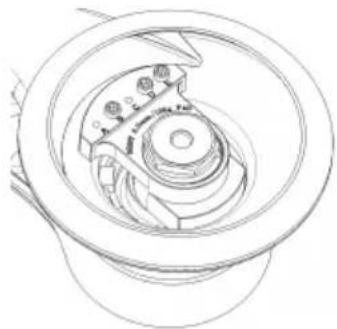
natural_image
Technical line drawing of a mechanical component with concentric rings and mounting holes (no text or symbols)natural_image
Circular black-and-white pattern with evenly spaced white dots on a dark background (no text or symbols)natural_image
Technical line drawing of a mechanical component with concentric rings and a central hub (no text or symbols)natural_image
Technical line drawing of a mechanical component with concentric rings and central hub (no text or symbols)natural_image
Technical line drawing of a mechanical component with no visible text or symbolsnatural_image
Technical line drawing of a mechanical component with no visible text or symbolsnatural_image
Circular black-and-white pattern with scattered white dots on a dark background (no text or symbols)natural_image
Technical line drawing of a mechanical component with no visible text or symbolsnatural_image
Technical line drawing of a mechanical component with no visible text or symbolsnatural_image
Technical line drawing of a mechanical assembly with concentric rings and central components (no text or symbols)natural_image
Technical line drawing of a mechanical component with no visible text or symbols- General Industry Safety & Health Regulations, part 1910, OSHA 2206, available from: Superintendent of Documents; Government Printing Office: Washington DC 20402
- Safety Code for Portable Air Tools, ANSI B186.1 (sikkerhedskode for bærbart trykluftværktøj), der kan rekvireres hos: American National Standards Institute, Inc.: 1430 Broadway: New York, New York 10018
natural_image
Circular black-and-white pattern with evenly spaced white dots on a dark background (no text or symbols)natural_image
Technical line drawing of a mechanical component with concentric rings and central hub (no text or symbols)
natural_image
Technical line drawing of a mechanical component with gears and shafts (no text or symbols)-
Maskinkonfiguration til brug med pad saver eller interface
-
Maskinkonfiguration fabriksindstilling

natural_image
Technical line drawing of a mechanical component with concentric rings and mounting holes (no text or symbols)
natural_image
Technical line drawing of a mechanical component with no visible text or symbols- Maskinkonfiguration fabriksindstilling
- Maskinkonfiguration til brug med pad saver eller interface
| Opstilling fabriksindstillingFigurModel | |||||||||
| Sekskantet møtrikSkrue | |||||||||
| EDCBAEDCBA | |||||||||
| ----XX-1550 | |||||||||
| ----XX-1580 | |||||||||
| ----XX-1625 | |||||||||
| ----XX-1650 | |||||||||
| ----XX-X-3680 | |||||||||
| Opstilling for padsaver/interfaceFigurModel | |||||||||
| Sekskantet møtrikSkrue | |||||||||
| EDCBAEDCBA | |||||||||
| --XXX--XXX2550 | |||||||||
| --XXX--XXX2580 | |||||||||
| --XXX--XXX2625 | |||||||||
| --XXX--XXX2650 | |||||||||
| ----XXXXX4680 | |||||||||
Fejlfindingsguide
- General Industry Safety & Health Regulations, part 1910, OSHA 2206, available from: Superintendent of Documents; Government Printing Office; Washington DC 20402
natural_image
Circular black background with evenly spaced white dots, no text or symbols presentnatural_image
Technical line drawing of a mechanical component with concentric rings and central hub (no text or symbols)
natural_image
Technical line drawing of a mechanical assembly with concentric rings and internal components (no text or symbols)natural_image
Technical line drawing of a mechanical assembly with no visible text or symbols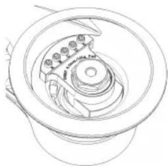
natural_image
Technical line drawing of a mechanical component with concentric rings and mounting holes (no text or symbols)natural_image
Circular pattern with evenly spaced white dots on a black background, no text or symbols present.natural_image
Technical line drawing of a mechanical component with concentric rings and a central hub (no text or symbols)natural_image
Technical line drawing of a mechanical component with concentric rings and central shaft (no text or symbols)natural_image
Technical line drawing of a mechanical component with no visible text or symbolsnatural_image
Technical line drawing of a mechanical assembly with no visible text or symbolsDeclaration of conformity
Mirka Ltd, 66850 Jeppo, Finland
declare under our sole responsibility that the Mirka® products (listed below and see "Technical data" table for particular model) to which this declaration relates are in conformity with the following standards or other normative documents: EN ISO 12100:2010, EN ISO 11148-8:2011, EN ISO 15744:2008 & EN ISO 28927-3:2009. In accordance with the directive 2006/42/EC.
Products: Mirka ^* PROS 150 mm (6"), 125 mm (5")
Jeppo 12.08.21
Place and date of issue

Manufacturer / Supplier
Mirka Ltd
66850 Jeppo, Finland
Tel.+358 20 760 2111
Fax +358 20 760 2290
www.mirka.comStefan Sjö

Original instructions. We reserve the right to make changes to this manual without prior notice.
Important
Read these safety and operating instructions carefully before installing, operating or maintaining this tool. Keep these instructions in a safe and accessible place. Read and comply with state and local regulations.
Required personal safety equipment

Read
operator's manual

Wear safety glasses

Wear
ear protection

Wear safety gloves

Wear
face mask
Symbols
 | Complies with EU relevant standards |
 | Complies with Eurasian conformity requirements |
 | Complies with Serbian conformity requirements |
 | Complies with UK relevant regulations |

Warning: Potential hazardous situation that may result in death or serious injury and/or property damage.
Caution: Potential hazardous situation that may result in minor or moderate injury and/or property damage.
Please read and comply with
- General Industry Safety & Health Regulations, part 1910, OSHA 2206, available from: Superintendent of Documents; Government Printing Office; Washington DC 20402
- Safety Code for Portable Air Tools, ANSI B186.1 available from: American National Standards Institute, Inc.; 1430 Broadway; New York, New York 10018
• State and local regulations

WARNING
- Always wear required personal safety protection in accordance with manufacturer's instructions and local/national standards while using this tool.
- Do not use a power tool if you are tired or under the influence of drugs, alcohol or medication.
- Read the Materials Safety Data Sheet (MSDS) for the working surface.
- Use the tool with dust extraction. A suitable dust extraction unit will reduce hazardous dust.
- Do not overreach. Keep proper footing and balance at all times.
- Do not wear loose clothing or jewellery. Keep your hair, clothing and gloves away from moving parts.
- Loose clothes, jewellery or long hair can be caught in moving parts.
- If any physical hand/wrist discomfort is experienced, stop working and seek medical attention.
- Hand, wrist and arm injury may result from repetitive work, motion and overexposure to vibrations.
- Do not operate power tools in explosive atmospheres, such as in the presence of flammable liquids, gases or dust.
- The tool is not electrically insulated. Check work area for live electricity, gas pipes, etc. before operation.

CAUTION
• Prevent unintentional starting.
- Remove pad wrench before connecting the tool to the air supply.
- Keep work area clean and well lit.
• Always ensure that the work piece to be sanded is firmly fixed.
- Before changing abrasive always disconnect the air supply.

Additional Safety Warnings
- Read all instructions before using this tool. All operators must be fully trained in usage and safety of this tool.
• All maintenance must be carried out by trained personnel. For service, contact Mirka authorized service centre!
• Always wear required safety equipment (see warnings). - The operator must be in a secure position and have a firm grip and footing on a solid floor.
• Always ensure that the work piece to be sanded is firmly fixed. - Check tool, backing pad, hose and fittings regularly for wear.
- Always take care to ensure your safety at work; never carry, store or leave the tool unattended with the air supply connected.
- Vacuum unit dust collection bag should be cleaned or replaced daily. Dust can be highly combustible. Cleaning or replacing of bag also assures optimum performance.
- Do not exceed maximum recommended air pressure of 6.2 bar (90 psig).
• Take care to avoid entanglement of the moving parts of the tool with clothing, ties, hair, cleaning rags, etc. - Keep hands clear of the spinning pad during use.
- If the tool appears to malfunction, remove from use immediately and arrange for service and repair.
- Before changing abrasive always disconnect the air supply. Take care to properly attach and centre the abrasive on the backing pad.
Technical data
| 680CV/NV650C | ||||||
| Orbit | 2.5 mm (3/32") | 5 mm (3/16") | 8 mm (5/16") | 2.5 mm (3/32") | 5 mm (3/16") | 8 mm (5/16") |
| CentralCentralCentralCentralNonV | ||||||
| Pad size | ∅ 125 mm (5") | ∅ 125 mm (5") | ∅ 125 mm (5") | ∅ 150 mm (6") | ∅ 150 mm (6") | ∅ 150 mm (6") |
| Product net weight | 0.89 kg (2.0 lbs) | 0.89 kg (2.0 lbs) | 0.91 kg (2.0 lbs) | 0.9 kg (2.0 lbs) | 0.93 kg (2.1 lbs) | 0.95 kg (2.1 lbs) |
| Height | 102 mm (4") | 102 mm (4") | 102 mm (4") | 102 mm (4") | 102 mm (4") | 102 mm (4") |
| 680CV/NV650CV | ||||||
| Length | 229 mm (9,02") | 229 mm (9,02") | 229 mm (9,02") | 229 mm (9,02") | 229 mm (9,02") | 229 mm (9,02") |
| Speed | 12,000 rpm | 12,000 rpm | 12,000 rpm | 12,000 rpm | 12,000 rpm | 12,000 rpm |
| Noise level | CV: | CV:76 dB(A) | CV:78 dB(A) | CV:75 dB(A) | CV:76 dB(A) | CV:77 dB(A) |
| Noise level | NV:75 dB(A) | NV:75 dB(A) | NV:77 dB(A) | NV:75 dB(A) | NV:76 dB(A) | NV:74 dB(A) |
| Power | 270 W | 270 W | 270 W | 270 W | 270 W | 270 W |
| Air consumption | 485 lpm | 485 lpm | 485 lpm | 485 lpm | 485 lpm | 485 lpm |
| Vibration level * | 2.8 m/s^2 | 2.4 m/s^2 | 3.8 m/s^2 | 2.3 m/s^2 | 3.2 m/s^2 | 3.4 m/s^2 |
| Vibrationemission uncertainty K * | 0.8 m/s^2 | 0.8 m/s^2 | 0.9 m/s^2 | 0.7 m/s^2 | 0.8 m/s^2 | 0.8 m/s^2 |
| 680DB650DB625D | |||||
| Orbit | 5 mm (3/16") | 8 mm (5/16") | 2.5 mm (3/32") | 5 mm (3/16") | 8 mm (5/16") |
| Vacuum type | Self-generated | Self-generated | Self-generated | Self-generated | Self-generated |
| Pad size | ∅ 125 mm (5") | ∅ 125 mm (5") | ∅ 150 mm (6") | ∅ 150 mm (6") | ∅ 150 mm (6") |
| Product net weight | 0.89 kg (2.0 lbs) | 0.91 kg (2.0 lbs) | 0.9 kg (2.0 lbs) | 0.93 kg (2.1 lbs) | 0.95 kg (2.1 lbs) |
| Height | 102 mm (4") | 102 mm (4") | 102 mm (4") | 102 mm (4") | 102 mm (4") |
| Length | 229 mm (9,02") | 229 mm (9,02") | 229 mm (9,02") | 229 mm (9,02") | 229 mm (9,02") |
| Speed | 12,000 rpm | 12,000 rpm | 12,000 rpm | 12,000 rpm | 12,000 rpm |
| Noise Level | 81.3 dB(A) | 80.9 dB(A) | 80.3 dB(A) | 78.2 dB(A) | 79.7 dB(A) |
| Power | 200 W | 200 W | 200 W | 200 W | 200 W |
| Air consumption | 485 lpm | 485 lpm | 485 lpm | 485 lpm | 485 lpm |
| Vibration level * | 2.8 m/s ^2 | 3.5 m/s ^2 | 2.3 m/s ^2 | 3.0 m/s ^2 | 2.5 m/s ^2 |
| Vibrationemission uncertainty K * | 0.8 m/s ^2 | 0.8 m/s ^2 | 0.7 m/s ^2 | 0.8 m/s ^2 | 0.7 m/s ^2 |
The noise test is carried out in accordance with EN ISO 15744:2008 – Hand-held non-electric power tools – Noise measurement code – Engineering method (grade 2).
The vibration test is carried out in accordance with ISO 28927-3 - Hand-held portable power tools – Test method for evaluation of vibration emission – Part 3: Polishers and rotary, orbital and random orbital sanders.
Specifications subject to change without prior notice. Model range may vary between markets.
* The values stated in the table are derived from laboratory testing in conformity with stated codes and standards and are not sufficient for risk evaluation. Values measured in a particular work place may be higher than the declared values. The actual exposure values and amount of risk or harm experienced by an individual are unique to each situation and depend upon the surrounding environment, the way the individual operates the machinery, the particular material being worked, work station design and the user's exposure time and physical condition. Mirka accepts no responsibility for the consequences of using declared values instead of actual exposure values for any individual risk assessment.
* Without dust bag and dust hose.
Further occupational health and safety information can be obtained from the following websites:
https://osha.europa.eu/en (Europe) or http://www.osha.gov (USA)
Proper use of tool
This sander is designed for sanding all types of materials i.e. metals, wood, stone, plastics, etc. using abrasive designed for this purpose. Do not use this sander for any other purpose than specified, without consulting your Mirka dealer. Only use Mirka backing pads that are designed for optimal performance with the brake seal. Never mount a backing pad without a spacing washer. Other backing pads may reduce performance and will increase vibrations.
Work stations
The tool is intended to be operated as a hand-held tool. It is always recommended that the tool should be used when standing on a solid floor. It can be in any position but before any such use, the operator must be in a secure position, having a firm grip and footing and be aware that the sander can develop a torque reaction. See the section "Operating instructions".
Operating instructions
When unpacking the tool, make sure it is intact, complete and has not been damaged in transport. Never use a damaged tool.
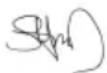
To attach air supply, lift up the cover and connect air supply, close the cover before operating the tool. Use a clean lubricated air supply that will give a measured air pressure at the tool of 6.2 bar (90 psig) when the tool is running with the lever fully pressed. It is recommended to use an approved 10 mm (3/8") x 8 m (25 ft) maximum length air hose. The tool should be connected to the air supply as shown in Figure 1.
Do not connect the tool to the compressed air system without incorporating an easy to reach and operate air shutoff valve. It is strongly recommended that an air filter, regulator and lubricator (FRL) are used as shown in Figure 1 as this will supply clean, lubricated air at the correct pressure to the tool. Details of such equipment can be obtained from your supplier. If such equipment is not used the tool should be manually lubricated.
To manually lubricate the tool, disconnect the air hose and put 2 to 3 drops of oil, Wurth art. no. 08930505 into the air connection on the tool. Reconnect the tool to the air supply and run the tool slowly for a few seconds to allow air to circulate the oil. If the tool is used frequently, lubricate it on a daily basis.
Lubricate the tool before longer storage or if the tool slows down or loses power.
It is recommended that the air pressure at the tool is 6.2 bar (90 psig) while the tool is running. The tool can run at lower pressures but never higher than 6.2 bar (90 psig).
Maintenance

Always disconnect the air supply before maintenance! Only use original Mirka spare parts!
Replacing the backing pad
- Insert the pad wrench between the backing pad and brake seal to hold the spindle nut.
- Turn the backing pad counterclockwise to remove it.
- Fit and tighten the new backing pad with washers.
- Remove the pad wrench.
Pad saver
Mirka pad savers are designed to protect the backing pad from wear and tear, when sanding aggressively and continuously with net products. These cost effective pad savers, placed between the backing pad and the sanding disc, should be changed regularly. The pad savers prolong the life of the backing pad.

natural_image
Circular black-and-white pattern with evenly spaced white dots on a dark background (no text or symbols)Replacing the brake seal
- Remove the backing pad as described above.
- Pull the old brake seal out of its groove.
- Fit the new brake seal in the groove.
- Fit the backing pad as described above.
- Check the brake seal function. By changing the number of washers between the spindle and backing pad, the effect of the brake seal can be adjusted.
Replacing the muffler kit
PROS NV/CV
- Lift up the cover.
- Remove the muffler cup by pushing it firmly to the side and insert a screwdriver between the cup and the hex nut, twist the screwdriver to release the cup from the housing.
• Reattach new muffler to the housing.
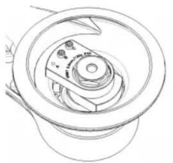
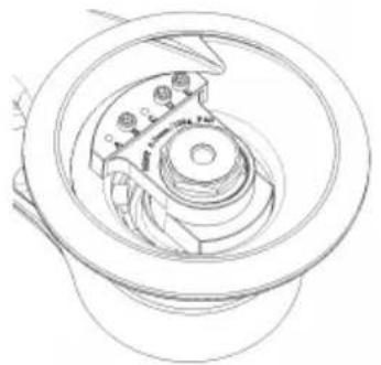
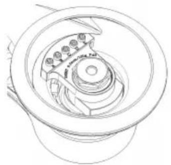
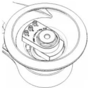
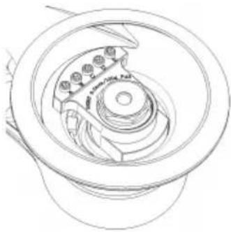
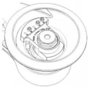
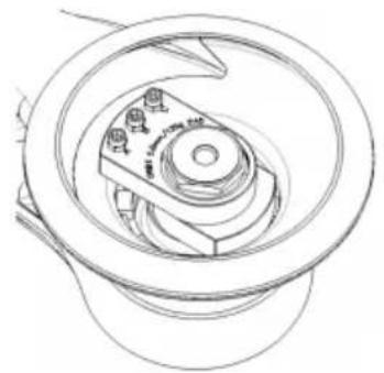
Reducing vibration when sanding with pad saver or interface
The level of vibration may increase when sanding with a pad saver or interface. Your Mirka tool has a feature to reduce this vibration. To use this feature, please follow these steps:
- Disconnect power cable.
- Remove backing pad.
- Add hex nuts and screws in accordance with the table below, tighten to 2 Nm.
natural_image
Technical line drawing of a mechanical component with no visible text or symbols- Machine configuration out of box.

natural_image
Technical line drawing of a mechanical component with gears and housing (no text or symbols)- Machine configuration for use with pad saver or interface.
natural_image
Technical line drawing of a mechanical component with concentric rings and mounting holes (no text or symbols)- Machine configuration out of box.
natural_image
Technical line drawing of a mechanical component with concentric rings and central hub (no text or symbols)- Machine configuration for use with pad saver or interface.
| Set-up out of boxPictureModel | |||||||||
| Hex nutScrew | |||||||||
| EDCBAEDCBA | |||||||||
| ----XX-1550 | |||||||||
| ----XX-1580 | |||||||||
| ----XX-1625 | |||||||||
| ----XX-1650 | |||||||||
| ----XX-X-3680 | |||||||||
| Set-up for padsaver/interfacePictureModel | |||||||||
| Hex nutScrew | |||||||||
| EDCBAEDCBA | |||||||||
| --XXX--XXX2550 | |||||||||
| --XXX--XXX2580 | |||||||||
| --XXX--XXX2625 | |||||||||
| --XXX--XXX2650 | |||||||||
| ----XXXXX4680 | |||||||||
Troubleshooting guide
| SolutionPossible causeSymptom | ||
| Low power and/ or low free speed. | Speed control set to low speed. | Turn the speed control to desired speed. |
| Low air pressure. | Check air supply (according to operating instructions). | |
| Exhaust plug not aligned (DB model). | Check that one of the four marks on the exhaust plug is aligned with the single mark below the exhaust plug. | |
| Clogged muffler. | Clean or replace the muffler. | |
| Plugged air inlet screen. | Clean or replace the screen. | |
| Internal air leakage in the motor housing. | Check motor assembly and alignment.Check air inlet O-ring alignment on motor assembly. | |
| Worn or broken vanes. | Install a complete set of new vanes and rotor (Kit F). | |
| Housing cracked or damaged. | Contact Mirka authorized service centre. | |
| Worn or broken spindle bearing. | Replace the worn or broken bearing (Kit A). | |
| Air leakage at the speed control. | Dirty, broken or bent valve spring, valve or valve seat. | Disassemble, inspect andreplace worn or damaged parts. |
| Incorrect assembly of air valve. | Remove air inlet connection and reassemble the air valve (207), with the valve stem (202) in its upper position. | |
| Vibration / rough operation. | Incorrect backing pad. | Only use Mirka backing pad 125 mm (5"), 150 mm (6"). |
| Addition of interface or other material. | Only use abrasive and/or interface designed for the machine. | |
| Damaged backing pad. | Replace the pad. Only use Mirka backing pad 125 mm (5"), 150 mm (6"). | |
| Worn or broken motor bearing(s). | Replace the worn or broken bearings. | |
| Too much vacuum on a flat surface can increase vibrations. | Lower the vacuum of your dust extraction unit. | |
| Low motor speed. | Increase motor speed with flow regulator, max 6.2 bar. |

Further service
Servicing must always be performed by trained personnel. To keep the tool warranty valid and ensure optimal tool safety and function, servicing must be carried out by a Mirka authorized service centre. To locate your local Mirka authorized service centre, contact Mirka Customer Service, your Mirka dealer or go to www.mirka.com
natural_image
Circular black-and-white pattern with evenly spaced white dots on a dark background (no text or symbols)natural_image
Technical line drawing of a mechanical component with concentric rings and central hub (no text or symbols)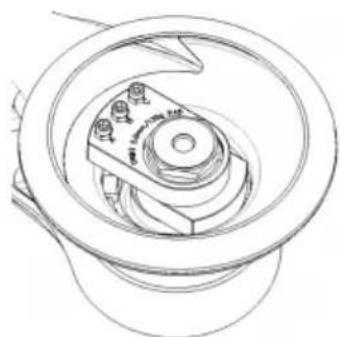
natural_image
Technical line drawing of a mechanical component with concentric rings and mounting holes (no text or symbols)natural_image
Technical line drawing of a mechanical component with concentric rings and central hub (no text or symbols)
natural_image
Technical line drawing of a mechanical assembly with no visible text or symbolsTooted: Mirka* PROS 150 mm (6"), 125 mm (5")
Jeppo 12.08.21
natural_image
Circular black-and-white pattern with evenly spaced white dots on a dark background (no text or symbols)natural_image
Technical line drawing of a mechanical component with concentric rings and a central hub (no text or symbols)natural_image
Technical line drawing of a mechanical component with concentric rings and mounting holes (no text or symbols)natural_image
Technical line drawing of a mechanical component with concentric rings and central hub (no text or symbols)natural_image
Technical line drawing of a mechanical component with concentric rings and mounting holes (no text or symbols)- General Industry Safety & Health Regulations, part 1910, OSHA 2206, Tilausosoite: Superintendent of Documents; Government Printing Office; Washington DC 20402
natural_image
Circular black-and-white pattern with evenly spaced white dots on a dark background (no text or symbols)natural_image
Technical line drawing of a mechanical component with concentric rings and a central hub (no text or symbols)natural_image
Technical line drawing of a mechanical component with concentric rings and mounting holes (no text or symbols)natural_image
Technical line drawing of a mechanical assembly with concentric rings and central components (no text or symbols)natural_image
Technical line drawing of a mechanical component with no visible text or symbolsnatural_image
Circular black-and-white pattern with scattered white dots on a dark background (no text or symbols)natural_image
Technical line drawing of a mechanical component with no visible text or symbols
natural_image
Technical line drawing of a mechanical component with concentric rings and mounting holes (no text or symbols)natural_image
Technical line drawing of a mechanical component with concentric rings and central hub (no text or symbols)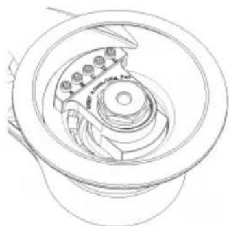
natural_image
Technical line drawing of a mechanical component with no visible text or symbolsnatural_image
Circular black-and-white pattern with evenly spaced white dots on a dark background (no text or symbols)Zamjena osovine kočnice
natural_image
Technical line drawing of a mechanical component with concentric rings and a central hub (no text or symbols)- Konfiguracija uređaja prilikom raspakiravanja.
natural_image
Technical line drawing of a mechanical component with concentric rings and mounting holes (no text or symbols)natural_image
Technical line drawing of a mechanical component with concentric rings and central hub (no text or symbols)- Konfiguracija uređaja prilikom raspakiravanja.
natural_image
Technical line drawing of a mechanical component with concentric rings and mounting holes (no text or symbols)natural_image
Circular black-and-white pattern with evenly spaced white dots on a dark background (no text or symbols)natural_image
Technical line drawing of a mechanical component with concentric rings and a central hub (no text or symbols)natural_image
Technical line drawing of a mechanical component with concentric rings and mounting holes (no text or symbols)natural_image
Technical line drawing of a mechanical component with concentric rings and mounting holes (no text or symbols)natural_image
Technical line drawing of a mechanical assembly with gears and housing (no text or symbols)natural_image
Circular black-and-white pattern with evenly spaced white dots on a dark background (no text or symbols)natural_image
Technical line drawing of a mechanical component with concentric rings and a central hub (no text or symbols)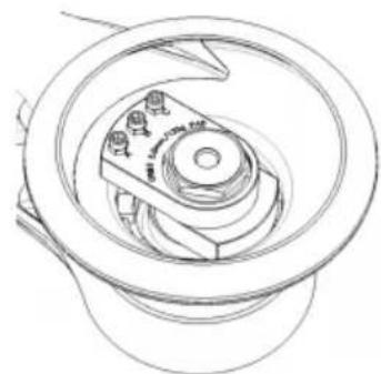
natural_image
Technical line drawing of a mechanical component with concentric rings and mounting holes (no text or symbols)natural_image
Technical line drawing of a mechanical assembly with concentric rings and central components (no text or symbols)
natural_image
Technical line drawing of a mechanical bearing assembly (no text or symbols)- 일반 산업안전보건규정(General Industry Safety & Health Regulations, part 1910, OSHA 2206, 자료 제공: Superintendent of Documents; Government Printing Office; Washington DC 20402).
- General Industry Safety & Health Regulations, part 1910, OSHA 2206, Kur galima gauti: Superintendent of Documents; Government Printing Office; Washington DC 20402
natural_image
Circular black-and-white pattern with evenly spaced white dots on a dark background (no text or symbols)natural_image
Technical line drawing of a mechanical component with concentric rings and a central hub (no text or symbols)natural_image
Technical line drawing of a mechanical component with concentric rings and mounting holes (no text or symbols)natural_image
Technical line drawing of a mechanical component with concentric rings and mounting holes (no text or symbols)natural_image
Technical line drawing of a mechanical assembly with gears and housing (no text or symbols)natural_image
Circular black-and-white pattern with evenly spaced white dots on a dark background (no text or symbols)natural_image
Technical line drawing of a mechanical component with concentric rings and a central hub (no text or symbols)natural_image
Technical line drawing of a mechanical component with concentric rings and mounting holes (no text or symbols)- Mašinas konfiguracija izmantošanai a r pamatnes aizsargu vai starpvirsmu.
natural_image
Technical line drawing of a mechanical component with concentric rings and mounting holes (no text or symbols)natural_image
Technical line drawing of a mechanical component with concentric rings and mounting holes (no text or symbols)natural_image
Circular black background with scattered white dots and a central dot (no text or symbols)natural_image
Technical line drawing of a mechanical component with concentric rings and a central hub (no text or symbols)natural_image
Technical line drawing of a mechanical assembly with gears and housing (no text or symbols)natural_image
Technical line drawing of a mechanical component with concentric rings and mounting holes (no text or symbols)natural_image
Technical line drawing of a mechanical component with no visible text or symbolsnatural_image
Circular black-and-white pattern with evenly spaced white dots on a dark background (no text or symbols)natural_image
Technical line drawing of a mechanical component with no visible text or symbolsnatural_image
Technical line drawing of a mechanical component with concentric rings and mounting holes (no text or symbols)natural_image
Technical line drawing of a mechanical assembly with no visible text or symbolsnatural_image
Technical line drawing of a mechanical component with no visible text or symbols- General Industry Safety & Health Regulations, Part 1910, OSHA 2206, kan fås fra: Superintendent of Documents; Government Printing Office; Washington DC 20402, USA
- Safety Code for Portable Air Tools, ANSI B186.1, kan fås fra: American National Standards Institute, Inc.; 1430 Broadway; New York, New York 10018, USA
• Statlige og regionale forskrifter

ADVARSEL
natural_image
Circular black-and-white pattern with evenly spaced white dots on a dark background (no text or symbols)Skifte ut bremseskiven
natural_image
Technical line drawing of a mechanical component with concentric rings and a central hub (no text or symbols)natural_image
Technical line drawing of a mechanical component with concentric rings and mounting holes (no text or symbols)natural_image
Technical line drawing of a mechanical assembly with concentric rings and central components (no text or symbols)natural_image
Technical line drawing of a mechanical component with no visible text or symbolsnatural_image
Circular black-and-white pattern with evenly spaced white dots on a dark background (no text or symbols)Wymiana uszczelki
natural_image
Technical line drawing of a mechanical component with concentric rings and central hub (no text or symbols)natural_image
Technical line drawing of a mechanical assembly with concentric rings and internal components (no text or symbols)natural_image
Technical line drawing of a mechanical component with concentric rings and mounting holes (no text or symbols)natural_image
Technical line drawing of a mechanical component with no visible text or symbolsnatural_image
Circular black-and-white pattern with evenly spaced white dots on a dark background (no text or symbols)natural_image
Technical line drawing of a mechanical component with no visible text or symbolsnatural_image
Technical line drawing of a mechanical component with concentric rings and mounting holes (no text or symbols)natural_image
Technical line drawing of a mechanical component with concentric rings and central hub (no text or symbols)natural_image
Technical line drawing of a mechanical component with no visible text or symbolsStefan Sjöberg, Director ExecutivCompania
Producător/Furnizor
Mirka Ltd
66850 Jeppo, Finlanda
Tel. +358 20 760 2111
Fax +358 20 760 2290
www.mirka.com

natural_image
Circular black-and-white pattern with evenly spaced white dots on a dark background (no text or symbols)natural_image
Technical line drawing of a mechanical component with concentric rings and a central hub (no text or symbols)natural_image
Technical line drawing of a mechanical component with concentric rings and mounting holes (no text or symbols)natural_image
Technical line drawing of a mechanical component with concentric rings and mounting holes (no text or symbols)natural_image
Technical line drawing of a mechanical component with concentric rings and mounting holes (no text or symbols)natural_image
Circular black background with scattered white dots and a central dot (no text or symbols)natural_image
Technical line drawing of a mechanical component with concentric rings and a central hub (no text or symbols)
natural_image
Technical line drawing of a mechanical component with concentric rings and internal gears (no text or symbols)natural_image
Technical line drawing of a mechanical assembly with no visible text or symbols
natural_image
Technical line drawing of a mechanical assembly with no visible text or symbolsnatural_image
Circular black-and-white pattern with evenly spaced white dots on a dark background (no text or symbols)Zamenjava zavornega tesnila
natural_image
Technical line drawing of a mechanical component with concentric rings and a central hub (no text or symbols)natural_image
Technical line drawing of a mechanical component with concentric rings and central shaft (no text or symbols)natural_image
Technical line drawing of a mechanical assembly with no visible text or symbolsnatural_image
Technical line drawing of a mechanical component with no visible text or symbolsnatural_image
Circular black-and-white pattern with evenly spaced white dots on a dark background (no text or symbols)Zamena zaptivke kočnice
- Uklonite potpornu podlogu na način opisan iznad.
- Izvucite staru zaptivku kočnice iz ležišta.
- Postavite novu zaptivku kočnice u ležište.
- Vratite potpornu podlogu na način opisan iznad.
- Proverite funkcionalnost zaptivke kočnice. Možete da podesite efekat zaptivke kočnice tako što ćete promeniti broj podloški između osovine i potporne podloge.
Zamena kompleta prigušivača
PROS NV/CV
- Podignite poklopac.
- Uklonite posudu za prigušivanje tako što ćete je čvrsto pomeriti u stranu i umetnuti odvijač između posude i navrtke. Okrenite odvijač da biste posudu odvojili od kućišta.
• Postavite novi prigušivač na kućište.
natural_image
Technical line drawing of a mechanical component with no visible text or symbols- Fabrička konfiguracija mašine.
natural_image
Technical line drawing of a mechanical component with gears and shafts (no text or symbols)natural_image
Technical line drawing of a mechanical component with concentric rings and mounting holes (no text or symbols)- Fabrička konfiguracija mašine.

natural_image
Technical line drawing of a mechanical component with concentric rings and central hub (no text or symbols)natural_image
Circular black-and-white pattern with evenly spaced white dots on a dark background (no text or symbols)natural_image
Technical line drawing of a mechanical component with concentric rings and a central hub (no text or symbols)- Maskinkonfiguration vid leverans.

natural_image
Technical line drawing of a mechanical component with concentric rings and central shaft (no text or symbols)natural_image
Technical line drawing of a mechanical assembly with no visible text or symbols- Maskinkonfiguration vid leverans.

natural_image
Technical line drawing of a mechanical component with no visible text or symbolsnatural_image
Circular black-and-white pattern with evenly spaced white dots on a dark background (no text or symbols)natural_image
Technical line drawing of a mechanical component with concentric rings and a central hub (no text or symbols)natural_image
Technical line drawing of a mechanical component with concentric rings and mounting holes (no text or symbols)natural_image
Technical line drawing of a mechanical component with concentric rings and mounting holes (no text or symbols)natural_image
Technical line drawing of a mechanical component with no visible text or symbolsnatural_image
Circular black-and-white pattern with evenly spaced white dots on a dark background (no text or symbols)更换制动密封
Declaration of conformity
| Mirka Ltd, 66850 Jeppo, Finlanddeclare under our sole responsibility that the Mirka® products (listed below and see "Technical data" table for particular model) to which this declaration relates are in conformity with the following standards or other normative documents: BS EN ISO 12100:2010, BS EN ISO 11148-8:2011, BS EN ISO 15744:2008 & BS EN ISO 28927-3:2009.. In accordance with the Supply of Machinery (Safety) Regulations 2008. | ||
| Products: Mirka® PROS 150 mm (6"), 125 mm (5") | ||
| Jeppo 12.08.21Place and date of issue |  Company Company |  Stefan Sjöberg, CEO Stefan Sjöberg, CEO |
| Manufacturer / SupplierMirka Ltd66850 Jeppo, FinlandTel. +358 20 760 2111Fax +358 20 760 2290www.mirka.com | Importer InformationMirka (UK) LtdSaxon HouseShirwell CrescentFurzton LakeMilton KeynesMK4 1GATel. +44 (0)1908 866100 |  |
This chapter is an addition to the English language chapter of the manual in order to fulfill the UKCA regulation requirements. Please refer to the English language chapter for more information about your product.
Statement of Compliance
We Mirka Ltd, hereby declare under our sole responsibility that the above-mentioned products, to which this statement relates, complies with the compliance conditions in Schedule 2 of The Product Security and Telecommunications Infrastructure (Security Requirements for Relevant Connectable Products) Regulations 2023.
The defined support period for the above-mentioned products is two years after the production date. The production date can be found on the marking plate of the products month/year.
geo
| Location | Marker | | -------- | ------ | | Central Europe | ● | | Eastern Europe | ● | | Western Europe | ● | | Northern Africa | ● | | Southern Africa | ● | | Middle East | ● | | Southeast Asia | ● | | Australia | ● | | North America | ● | | South America | ● | | Europe (not labeled) | ● | | Finland (not labeled) | ● |MirkaLtd
Finland
BrazilMirkaBrasilLtda.
BelgiumMirkaBelgiumLogisticsNV
CanadaMirkaCanadalnc.
ChinaMirkaTradingShanghaiCo.,Ltd
Finland&BalticsMirkaLtd
FranceMirkaFranceSarl
GermanyMirkaGmbH
IndiaMirkalndiaPvtLtd
ItalyMirkaltalias.r.l., CafroS.p.A.
MexicoMirkaMexicanaS.A.deC.V.
NetherlandsMirkaBeneluxB.V
PolandMirkaPolandSp.zo.o
SingaporeMirkaAsiaPacificPteLtd
SpainKWHMirkalbéricaS.A.U.
SwedenMirkaScandinaviaAB
TurkeyMirkaTurkeyZimparaLtdŞirketi
UnitedKingdomMirka(UK)Ltd
UnitedArabEmiratesMirkaMiddleEastFZCO
USAMirkaUSAInc.
Forcontactinformation,
pleasevisitwww.mirka.com