BPM12 - Hand blender YORKVILLE - Free user manual and instructions
Find the device manual for free BPM12 YORKVILLE in PDF.

User questions about BPM12 YORKVILLE
0 question about this device. Answer the ones you know or ask your own.
Ask a new question about this device
Download the instructions for your Hand blender in PDF format for free! Find your manual BPM12 - YORKVILLE and take your electronic device back in hand. On this page are published all the documents necessary for the use of your device. BPM12 by YORKVILLE.
USER MANUAL BPM12 YORKVILLE
battery powered live sound mixer
IMPORTANT SAFETY INSTRUCTIONS

This Lightning Bash with arrowhead symbol. Within an
equationical triangle, is intended to relax the user to the presence of unobstructed dangerous areas. This is an extreme example of this endoscopy that may be of sufficient magnitude to constitute a risk of electric shock to persons.
The DO NOT STACK symbol is intended to alert the user that the product shall not be
verically stacked because of the nature of the product.

m = 311 ;
CAUTION·AVIS
RISK OF ELECTRIC SHOCK DO NOT OPEN RISQUE DE CHOC ELECTRIQUE NE PAS OUVIR


The explanation point within an equilateral triangle is intended to alter the user to the presence of important operating and maintenance (servicing) instructions in the literature accompanying the appliance.

NOT TO BE SERVICED BY USERS

CAUTION: OVERHEAD LOAD
ATTENTION: CHARGE AERIENE
FOLLOW ALL INSTRUCTIONS SUVEZ TOUTES LES INSTRUCTIONS
Instructions pertaining to a risk of fire, electric shock, or injury to a person
CAUTION: TO REDUCE THE RISK OF ELECTRIC SHOCK, DO NOT REMOVE COVER (OR BACK).
ER SERVICEABLE PARTS INSIDE. REFER SERVICING TO QUALIFIED SERVICE
PERSONNEL, THIS DEVICE IS FOR INDOOR USE ONLY!
INSTALLED BATTERY PACKS SHALL NOT BE EXPOSED TO EXCESSIVE HEAT
SUCH AS SUNSHINE, FIRE OR THE LIKE
Read Instructions: The Owner's Manual should be read and understood before operation of your unit. Please, save these instructions for future reference and heed all warnings.
Cleaning: Clean only with dry cloth.
Packaging: Keep the box and packaging materials, in case the unit needs to be returned for service.
Warning: To reduce the risk of fire or electric shock, do not expose this apparatus to rain or moisture. Do not use this apparatus near water!
Warning: When using electric products, basic precautions should always be followed, including the following:
Power Sources
Your unit should be connected to a power source only of the voltage specified in the owner's manual or as marked on the unit. This unit has a polarized plug. Do not use with an extension cord or receptacle unless the plug can be fully inserted. Pracuations should be taken so that the grounding scheme on the unit is not defeated. An apparatus with CLASS I construction shall be connected to a Mains socket outlet with a protective earthing connection. Where the MAINS plug or an appliance coupler is used as the disconnected device, the disconnect device shall remain readily operable.
Hazards
Do not place this product on an unstable cart, stand, tripod, bracket or table. The product may fall, causing serious personal injury and serious damage to the product. Use only with cart, stand, tripod, bracket, or table recommended by the manufacturer or sold with the product. Follow the manufacturer's instructions when installing the product and use mounting accessories recommended by the manufacturer. Only use attachments/ accessories specified by the manufacturer.
Equipment that is suspended overhead must use a secondary safeguard to prevent personal injury in the event the primary mounting mechanism fails. Safety eyebots attached to the equipment are galvanized steel which can be used together to implement a fail safe mounting thus ensuring the safety of the system and the equipment.
Improper installation can result in bodily injury or death. If you are not qualified to attempt the installation get help from a professional structural engineer. Male: Pronounced use of bestabones of a high vulture may cause health discharge to your ears.
The apparatus should not be exposed to dripping or spashing water; no objects filled with liquids should be placed on the apparatus.
Terms marked with the "lightning bolt" are hazardous live; the external wiring connected to these terminals require installation by an instructed person or the use of ready made laces or cords.
Ensure that proper ventilation is provided around the appliance. Do not install near any heat sources such as radiators, heat registers, stoves, or other apparatus (including amplifiers) that produce heat.
No naked flame sources, such as lighted candles, should be placed on the apparatus.
Power Cord
Do not defeat the safety purpose of the piloted or grounding-type plug. Apoietized plug has two blades with one wider than the other. A grounding type plug has two blades and a third grounding plug. The wide blade or the thin plug are provided for your safety. If the provided plug does not fit into your outlet, consult an electrician for replacement of the obsolete outlet. The AC supply cord should be routed so that it is unlikely that it will be damaged. Protect the power cord from being walked on or pinched particularly at plugs. If the AC supply cord is damaged DO NOT OPERATE THE UNIT. To completely disconnect this apparatus from the AC Main's, disconnect the power supply cord plug from the AC receptacle. The main's plug of the power supply cord shall remain readily operable.
Unplug this apparatus during lightning slorms or when unused for long periods of time.
Service
The unit should be serviced only by qualified service personnel. Servicing is required when the apparatus has been damaged in any way, such as power-supply cord or plug is damaged, liquid has been spilled or objects have fallen into the apparatus, the apparatus has been exposed to rain or moisture, does not operate normally, requires battery pack replacement or has been dropped. Disconnect power before servicing!
IMPORTANT SAFETY INSTRUCTIONS

The Lightning Flash with arrowhead symbol within an equilateral triangle, is intended to alert the user to the presence of unruptured "dangerous voltage" within the product enclosure that may be of sufficient magnitude to constitute a risk of shock to persons

The exclamation point within an equilateral triangle is intered to aet the user to the presence of important operating and maintenance (servicing) instructions in the literature accompanying the product
- Read these instructions.
- Keep these instructions.
- Heed all warnings.
- Follow all Instructions
- Do not use this apparatus near water
- Clean only with dry cloth.
- Do not block any ventilation openings, Install in accordance with the manufacturer's instructions.
- Do not install near any heal sources such as racistors, heal registers, sloves, or other apparatus (including amplifiers) that produce heat.
- Do not defeat the safety purpose of the poziated or grounding-type plug. A poizetized plug has two blades with one vester than the other. A grounding-type plug has two blades and a third grounding plug. The ends blade or the third prongs are provided for your safety. If the provided plug does not meet the safety requirements, you will be required to replace it with a new one.
- Protect the power cord from being walked on or plashed particularly at plugs, convenience receptacles, and the point where they exit from the apparatus.
- Only use attachments/accessories specified by the manufacturer.
- Use only with the cart, stand, tripod, bracket, or table supplied by the manufacturer, or sold with the apparatus. When a cart is used, use caution when allowing the cart/apparatus combination to avoid injury from lip-over.
- Unplug this apparatus during lightning storms or when unused for long periods of time
- Refer all servicing to qualified service personnel. Servicing is required when the apparatus has been damaged in any way, such as power-supplying equipment or other equipment that has been spilled or objects have fallen into the apparatus, the apparatus has been exposed to rain or moisture, does not coalesce normally, or has been drooped.
WARNING:
To reduce the risk of fire or electric shock do not expose this apparatus to rain or moisture and objects filled with liquids, such as vases, should not be placed on this apparatus. - To completely disconnect this apparatus from the ac mains, disconnect the power supply cord plug from the ac receptacle.
- The mains plug of the power supply cord or appliance coupler shall remain readily accessible.

DOC-Safety-5v0+UL60065-00-1v9·February 2, 2022
Table of Contents
Important Safety Instructions - English/Français......i
Table of Contents.
EMC Declaration TYPE B - English/Français 1
Introduction 2
Features 2
Input Channels. 2
1. Microphone Inputs 2
2. Line Inputs 2
3. Gain 2
4. Set/Clip and Clip LEDs 2
5. Compressor (Mono Channels) 3
6.100 Hz Filter 3
7. Mono Channel EQ. 3
8. Stereo Channel EQ 3
9. Mon 1 and Mon 2 (Monitor)
10.EFX 4
11. Pan and Balance 4
12. Channel Fader 4
13.Mute 4
14. Solo 4
15.Mute Zone 4
Main Section. 4
1.Top Panel Connections 4
2. Phantom Power 4
3.Media In 4
4. Bluetooth® Receiver 4
5. Power Only (USB-A) 5
6. Media In/Out (USB-C) 5
7. Battery Status and Charging 5
8. Graphic Equalizer 5
9. Internal Digital Effects (EFX) 5
10. EFX Send Controls and Return to Main Fader ....5
11. Mon 1 and Mon 2 Fader..
12. Phones 6
13. VU Meter.. 6
14. Media In Level 6
15. Break Switch.. 6
16. Media Out 6
17. Zone/Sub 6
18. MAIN Fader 6
Rear Panel 6
1. Power Switch, IEC and Fuse 6
2. Line Outputs 7
Introduction 8
Section Principale 10
Specifications - English 14
Spcifications - Frangois 14
Block Diagram 15
Warranty - English / Français. 16
Rear Page 17
This equipment has been tested and found to comply with the limits for a Class B digital device, pursuant to part 15 of the FCC Rules. These limits are designed to provide reasonable protection against harmful interference in a residential installation. This equipment generates, uses and can radiate radio frequency energy, and if not installed and used in accordance with the instructions, may cause harmful interference to radio communications. However, there is no guarantee that interference will not occur in a particular installation. If this equipment does cause harmful interference to radio or television reception, which can be determined by turning the equipment off and on, the user is encouraged to try to correct the interference by one or more of the following measures:
- Recipient or relocate the receiving antenna.
-
Increase the separation between the equipment and receiver.
-
Connect the equipment into an outlet on a circuit different from that to which the receiver is connected.
- Consult the dealer or an experienced radioTV technician for help.
compliance-EMC Declaration CLASS B BLUETOOTH-OM-COPY 00 2/0
Introduction
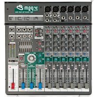
Thank you for choosing the BPM12 mixer from Yorkville Sound. It can be powered by standard AC, USB-C, or the built-in rechargeable battery, so it's a natural choice to pair with Yorkville battery-powered PA systems for truly mobile performances. With flexible features and Yorkville's renowned reliability, the BPM12 can help your event sound its best in any venue, anywhere.
Features
12-channel compact mixer (8 mono + 2 stereo channels)
- 10 mic preamps with global 24V phantom power
- Up to 18 hours of battery life
16 onboard adjustable effects
- Built-in compression on mono input channels and internal effects
- Assignable 9-band graphic EQ
2 Monitor Out busses
Zone/Sub output with independent mute per input channel
- Bluetooth®, 1/8" Media In, and USB-C Media In/Out connections
- Break switch to mute channel inputs while allowing audio from media inputs
- 5V USB-A port to power external devices
Input Channels
Mono channels feature Combi-Jacks that accept both low-impedance XLR and high-impedance 1/4'' balanced inputs. Stereo channels each have one XLR and two 1/4'' line-level inputs.
1. Microphone Inputs
The BPM12 accepts microphones with impedances ranging from 50 Ω through 10 kΩ. All low-impedance microphones are compatible. Most high-impedance microphones will work, provided that their XLR connection is wired with the audio signal on pin 2, and with pin 3 connected to pin 1.
Phantom power is available on all mic inputs, and can be turned on or off globally.
2. Line Inputs
Line-level signals can be connected to the balanced 1/4'' inputs on the mono or stereo channels. All mono channels have high-impedance 1/4'' inputs, which allow the direct connection of electric guitars, basses, acoustic pickups, and high-impedance microphones. Unbalanced sources can be connected using a standard unbalanced cable.
The two stereo channels will also work with mono signals, provided the source is connected to the L/Mono input. If a mono signal is connected to the R input on a stereo channel, it will only be heard in the right channel.
If you need more than two stereo channels, you can connect the left and right sides of a stereo signal to two mono channels. Adjust their pan controls fully to the left and right to preserve the stereo image.
3. Gain
The BPM12 features active channel input circuitry with exceptionally high audio headroom. The Gain control on each channel lets you boost signals by up to 72 dB.
4. Set/Clip and Clip LEDs
Each mono channel has a Set/Clip LED, and each stereo channel has a Clip LED. These indicate signal level and help ensure proper gain staging for the highest headroom and lowest noise. Clip LEDs will illuminate red when the signal is 3 dB below the channel's actual clipping level.
To set the input level for each channel, start by setting the channel fader to its lowest position the Gain control fully counter-clockwise.
For mono channels:
With the audio source playing, gradually turn the Gain control clockwise until the Set/Clip LED begins to flash green, indicating the optimal input level.
If the Set/Clip LED remains on continuously, it indicates that the channel compressor (described below) is active. Turning the Gain control counter-clockwise until the Set/Clip LED stops flashing will deactivate the compressor.


For stereo channels:
With the audio source playing, gradually turn the Gain control clockwise until it is at or just below the level at which the Clip LED occasionally flashes red during peaks in the loudest passages. Because the LED threshold is below the point of actual clipping, occasional illumination should not generally indicate audible distortion.
For all channels:
You can alternatively press a channel's Solo button to display that channel's pre-fader signal level on the VU meter in the master section. Adjust the channel's Gain control so that the LEDs corresponding to 0 VU illuminate on the loudest peaks.
Once the Gain control is set, turn up the channel fader to the desired level.
5. Compressor (Mono Channels)
Each mono input channel features a built-in soft-knee compressor. It controls dynamic range by reducing the volume of loud signals that exceed 0 dBV, resulting in a more consistent output level. The compressor works automatically in the background and only affects the signal as it approaches clipping level.
You can increase or decrease the amount of compression by raising or lowering the channel's Gain control. For more compression, set the Gain level so the Set/Clip LED flashes along to the input signal. At this point, the dynamic range of the source should be unaffected. Then, slowly turn the Gain control clockwise so the Set/Clip LED remains illuminated longer during peaks in the signal. If necessary, adjust the channel's fader to maintain a consistent level in the mix.
6. 100 Hz Filter
This switch activates a high-pass filter that rolls off frequencies below 100Hz with a slope of 18 dB per octave. The filter serves two important functions. Firstly, it can eliminate low-frequency noise and rumble to increase the clarity of your mix. Secondly, by removing low-frequency content from higher-register sources such as vocals, guitars, or wind instruments, these filters can create more space in the mix for lower-register sources such as the kick drum or bass guitar.
7. Mono Channel EQ
Mono channels feature a 3-band EQ. The Low and High bands are fixed at 80Hz and 12kHz , and the Mid frequency is variable between 150Hz and 5kHz . Each band offers up to 15dB of boost or cut, for subtle enhancements or dramatic changes. Please note that the wide range of the Mid Sweep control means that the Mid EQ may interact with the High and Low bands.
For live sound, you'll generally cut frequencies to solve mix problems rather than boost them, and the best approach is often to make the fewest possible adjustments. Subtle changes can reduce the risk of feedback when boosting, and preserve the character of each source.
8. Stereo Channel EQ
Stereo channels feature a 4-band EQ. Frequencies are fixed at 80Hz for the Low band, 400Hz for the Low Mid, 3kHz for the High Mid, and 12kHz for the High.
9. Mon 1 and Mon 2 (Monitor)
These controls can be used to create two separate monitor mixes. They adjust the signal level sent from each channel to the Mon 1 and Mon 2 faders in the master section and the corresponding outputs on the rear panel. The monitor sends are pre-fader, so you can freely make changes to the main mix levels without affecting your monitor mixes.
If feedback occurs, turning down the Mon 1 or Mon 2 faders can determine if the feedback is caused by microphones on stage picking up sound from the monitors. If that is the case, take the following steps:
- Identify whether Mon 1 or Mon 2 is causing the feedback.
- Turn up the corresponding fader in the Main section until feedback begins.
- Turn down the corresponding Mon control on each channel to identify which channels are contributing to the feedback.
- On channels which aren't causing feedback, return the monitor control to its original level.
- On channels which are causing feedback, set the Mon control below the point at which feedback occurs.
- If this doesn't fully eliminate feedback, you can also assign the graphic EQ in the Main section to the Mon 1 and Mon 2 mixes and attenuate each slider in turn until the feedback stops. Return any sliders which don't affect feedback to their original positions.


10. EFX
This controls the level of a post-fader send which is routed to the onboard digital effects, and to the EFX Send output for use with external processors. Signals from the channel EFX controls sum at the EFX Send control in the Main section.
If you don't require effects, you can also use the EFX controls as an additional monitor send. Please note that, unlike the pre-fader Mon 1 and Mon 2 controls, adjusting the channel faders will also change the mix at the EFX Send.
11. Pan and Balance
The post-fader Pan controls on mono channels and Balance controls on stereo channels adjust each channel's position in the stereo image of the main mix. Signals are compensated to maintain a consistent level across the stereo field.
12. Channel Fader
This controls the channel level. The fader taper is condensed at the upper and lower extremes, so you can quickly raise or lower volume, and expanded in the upper-middle area for precise adjustments.
13. Mute
This switch mutes its respective channel.
14. Solo
This switch solos the pre-fader audio of the selected channel in the VU meters and Phones output. This lets you easily set individual gain levels even while a full band is playing. The signal is taken before the Mute switch, so you can cue up audio sources in headphones before unmuting and adding them to the main mix.
Solo buttons on the BPM12 only affect the signal at the Phones output, so there is no risk of inadvertently disrupting your main mix.
15. Mute Zone
This switch will mute the channel in the mix sent to the Zone/Sub output on the rear of the mixer. See the "Zone/Sub" section for more details.

Main Section
1. Top Panel Connections
Connections for the EFX Send output, EFX Footswitch, 1/8'' Media In, and headphones are located to the right of the channel inputs for convenient access.
2. Phantom Power
This switch activates 24V phantom power globally across all microphone inputs. This is typically used to power condenser microphones, and will generally have no effect on other modern microphone designs. We recommend turning the phantom power off before connecting or disconnecting microphones to avoid loud pops.
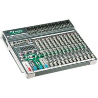
Other compact mixers from Yorkville Sound, such as the PGM8 and VGM14, feature 48V phantom power to work with both live and studio microphones. We selected 24V for the BPM12 to preserve battery life, and because it is sufficient to power practically all live handheld microphones. If you want to use a mic that requires more than 24V, we recommend connecting it to an external preamp or power supply.

3\.Media In
For background music or other media playback, the BPM12 lets you connect stereo audio sources by 1/8'' TRS, USB-C, or Bluetooth®. The signal level from these sources to the main mix can be adjusted with the Media In control located below the stereo LED meters. The LED next to the knob will illuminate to indicate clipping.
4. Bluetooth® Receiver
The integrated Bluetooth receiver lets you wirelessly transmit audio from a computer or mobile device.
The receiver will be deactivated by default when the BPM 12 is powered on. To activate the receiver, tap the Bluetooth button in the upper right of the top panel, and the BPM12 will attempt to reconnect to the last connected source. To pair a new device, press and hold the button for 4 seconds.
A blue LED will indicate the current status of the Bluetooth connection as described in this chart:
| LinkedLink-BackStandbyPairing | |||
| ON | ON, blinks 1x every 2 seconds. | Flashes 1x every 2 seconds | Flashes 2x per second |
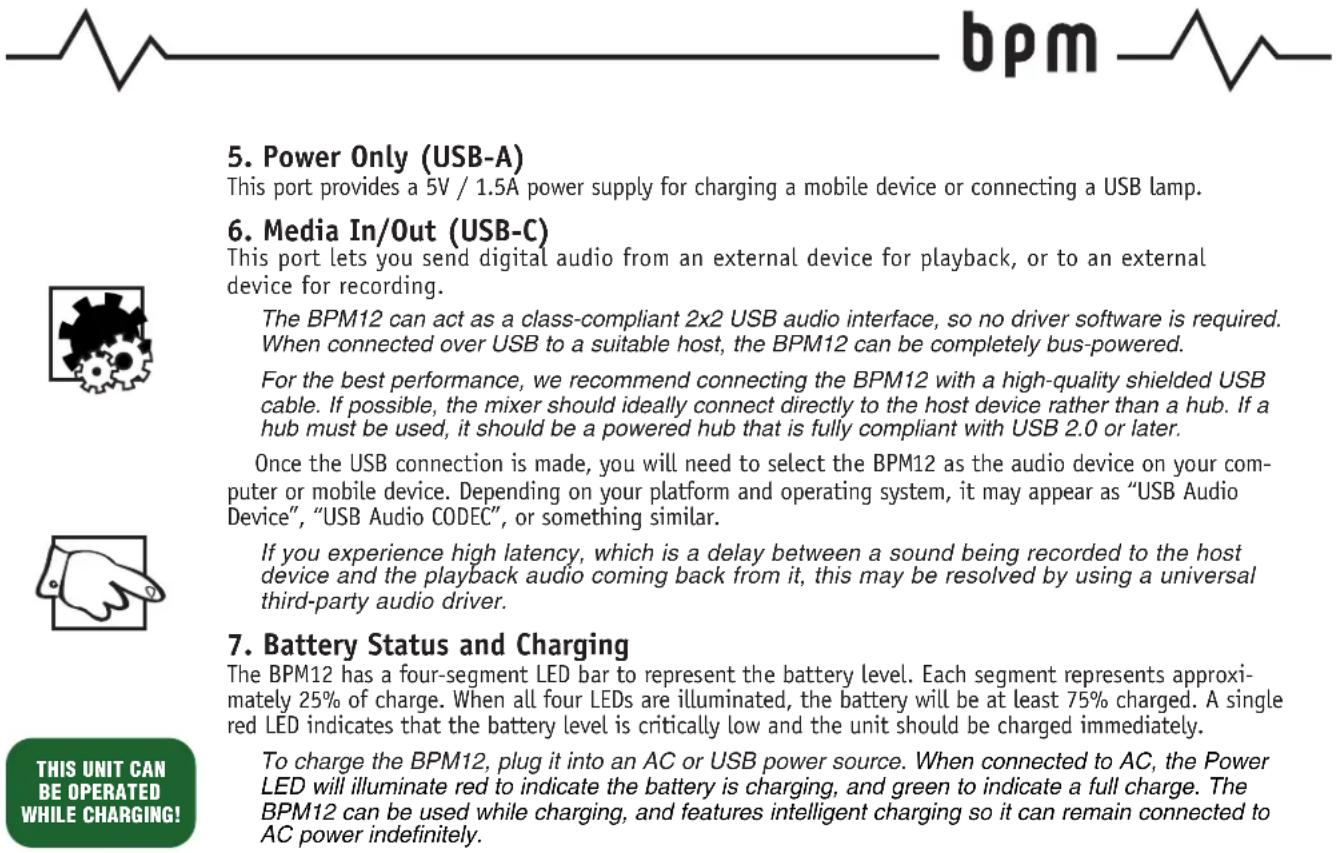
5. Power Only (USB-A)
This port provides a 5V / 1.5A power supply for charging a mobile device or connecting a USB lamp.
6. Media In/Out (USB-C)
This port lets you send digital audio from an external device for playback, or to an external device for recording.
The BPM12 can act as a class-compliant 2x2 USB audio interface, so no driver software is required. When connected over USB to a suitable host, the BPM12 can be completely bus-powered.
For the best performance, we recommend connecting the BPM12 with a high-quality shielded USB cable. If possible, the mixer should ideally connect directly to the host device rather than a hub. If a hub must be used, it should be a powered hub that is fully compliant with USB 2.0 or later.
Once the USB connection is made, you will need to select the BPM12 as the audio device on your computer or mobile device. Depending on your platform and operating system, it may appear as "USB Audio Device", "USB Audio CODEC", or something similar.
If you experience high latency, which is a delay between a sound being recorded to the host device and the playback audio coming back from it, this may be resolved by using a universal third-party audio driver.
7. Battery Status and Charging
The BPM12 has a four-segment LED bar to represent the battery level. Each segment represents approximately 25% of charge. When all four LEDs are illuminated, the battery will be at least 75% charged. A single red LED indicates that the battery level is critically low and the unit should be charged immediately.
To charge the BPM12, plug it into an AC or USB power source. When connected to AC, the Power LED will illuminate red to indicate the battery is charging, and green to indicate a full charge. The BPM12 can be used while charging, and features intelligent charging so it can remain connected to AC power indefinitely.
If the BPM12 will not be used for several months, we recommend charging it periodically to maintain battery health. If the mixer is stored for an extended period without occasional charging, we recommend plugging it in for approximately 24 hours before running the mixer on battery power.
The BPM12 will not charge when the temperature is below 0^ or above 45^

The BPM12 is delivered with 20 - 30% of the charge capacity. Please charge your unit for 5-hours prior to initial battery operation!
8. Graphic Equalizer
The stereo graphic equalizer offers 12 dB of boost or cut on each of the 9 adjustable bands. It can be assigned to either the Main or Mon 1/2 outputs using the button to the left of the sliders, and can be used to enhance the mix, compensate for room acoustics, or reduce feedback.
9. Internal Digital Effects (EFX)
The EFX Select knob lets you choose from 16 effect algorithms. These include multiple reverb, echo, and modulation options, as well as an acoustic guitar mode to enhance the sound of piezo pickups, and a harmonizer. A preset list is on the main panel to the left of the EFX Select knob for easy reference, and the Modify control lets you quickly tailor each effect to the performance.
Audio sent to the internal effects passes through a compressor to optimize the signal level. If the Clip LED next to the EFX Send knob illuminates, it indicates maximum compression. We recommend setting the EFX Send level at or below the point at which the Clip LED only illuminates occasionally during loud passages.
10. EFX Send Controls and Return to Main Fader
Audio from the channel EFX controls sum at the main EFX Send control. The summed signal is sent to both the internal digital effects and the EFX Send output, so you can simultaneously use the onboard effects and an external processor.
If using an external processor, please note that the BPM12 does not have a dedicated effect return. Connect the processor outputs to channel inputs on the mixer. EFX controls on those channels must be set fully counter-clockwise to avoid a feedback loop.
For the optimal signal level, turn the EFX Send control until the Clip LED at or just below the point at which the Clip LED to the left of the knob illuminates only occasionally during loud passages, adjust-


ing the EFX controls on the input channels if necessary. Press the Solo button next to the EFX Send knob to isolate the EFX Send signal in the LED meters and headphone output for ease of reference.
Use the EFX to Mon 1 and EFX to Mon 2 controls to adjust the level of the onboard effects in the monitor outputs, and use the EFX Return to Main fader to adjust the level of the onboard effects in the main mix.
The internal effects can be muted remotely by connecting a latching footswitch, such as an Apex AFS1 or equivalent, to the EFX Footswitch jack on the top panel. This footswitch will override the Mute button on the EFX Return to Main fader.
11. Mon 1 and Mon 2 Fader
Audio from the channel Mon 1 and Mon 2 controls sum at the Mon 1 and Mon 2 faders, which control the signal level sent to their corresponding outputs. Each monitor fader has a corresponding Mute and Solo button.
12. Phones
The Phones control adjusts the volume of the signal at the Phones output. This output will receive either the main mix signal or the signal from any active Solo switches.
The Phones output is compatible with stereo headphones that have a minimum impedance of 8 For the best performance, we recommend using headphones with an impedance of 30 or higher.
13. VU Meter
The VU meter indicates the post-EQ level of the left and right channels. We recommend setting levels such that the loudest peaks in the signal generally reach 0 dB on the meters. Occasional illumination of the yellow +3 and +6 LEDs is generally acceptable as long as you don't hear audible distortion. Illumination of the red +10 LEDs indicates the possibility of clipping and should be avoided.
14. Media In Level
The Media In knob adjusts the level going from the 1/8'' , USB and Bluetooth inputs to the Main fader.
15. Break Switch
Pressing this switch will mute channels 1 through 12, background audio can be played from the media inputs during program breaks, without any background noise from live mics on stage.
When the switch is engaged, the LED to the left of the switch will blink, along with the mute switches on the input channels.
16. Media Out
This knob controls the signal level going to the USB output. It is unaffected by the Main fader, so you can set an optimal recording level independent of any volume changes you need to make in the room.
17. Zone/Sub
This controls the signal level going to the Zone/Sub output. It receives a sum of the post-fader signals from the channel inputs, media inputs, and onboard effects. This can provide an adjustable mono signal for an additional loudspeaker or distributed audio system, with the convenience of a dedicated level control at your console.
Input channels and the onboard effects can be excluded from the Zone/Sub mix using their respective Mute Zone buttons. This can be especially valuable when using the output to drive a subwoofer, so that you can remove elements such as vocal microphones, and send only low-register instruments such as kick drum or bass guitar.
18. MAIN Fader
This fader controls the level of the combined signal from the channel inputs, media inputs, and onboard effects that is sent to the Main Out jacks on the rear panel.
Rear Panel
1. Power Switch, IEC and Fuse
The power button is on the rear panel between the IEC power socket and audio outputs.
The BPM12 uses a T500mAL (slo-blo) fuse. The fuse drawer is located on the IEC socket. If you suspect the fuse needs replacement, take the following steps.
- Confirm that there is 100-240V~ power at the outlet to which the BPM12 power cable is connected.
- Confirm that the power cable is firmly connected to the BPM12 and the power switch is turned on.
-
If the Power LED on the BPM12 does not illuminate when the Power button is in the On position, turn the mixer off and disconnect the power cord from the unit.
-
When the power cable is removed, you will be able to see a small slot on top of the fuse drawer. Insert a small screwdriver into the slot and gently apply pressure to slide the fuse drawer out of the mixer.
- The fuse drawer can hold two fuses. The fuse in use is in a clip on the side of the drawer that is inserted into the mixer. The sides of the fuse will be exposed when in the clip. A spare fuse can be kept in the rectangular compartment on the opposite side of the drawer. Remove the fuse in use from the clip to inspect it. If the filament in the fuse is broken, the fuse must be replaced. It is imperative that you replace it with the same fuse type.
- Slide the fuse drawer back into the BPM12, reconnect the power cable, and turn on the mixer. If the new fuse also blows, then your BPM12 may require service from an authorized technician.
2. Line Outputs
XLR and 1/4'' connectors for the Zone/Sub, Main L/R, and Mon 1/2 outputs are located on the rear panel. These are balanced, low-impedance outputs, and we recommend using high-quality shielded cables for the best audio performance.
Introduction
Powered or Passive Battery and/or AC Mains Powered
Frequency Response +/- 1dB 20Hz-20kHz
Typical THD+N (1kHz)
Maximum Main Output Level (<1% THD+N)
Main Output Noise Level (Main + 1 Mono Ch @ 0dB)
Mono Channel Equalization
Stereo Channel Equalization
Main Output Equalization
Mono Channel Maximum Gain
Stereo Channel Maximum Gain
Media In Channel Gain
Ch. 1-8 Audio Inputs 8x Mono Mic/Line Combo Jacks
Ch. 9-12 Audio Inputs 2x Stereo 1/4" Line w/XLR Mono Mic Inputs
Stereo Media Inputs USB-C Audio, Bluetooth, 1/8" Aux (3.5mm)
XLR and 1/4" Balanced Audio Outputs Stereo Main Out, Mono Zone/Sub Out, Mon 1, Mon 2
Other Audio Outputs 1/4" Headphone Out, USB-C Media Out, 1/4" Balanced EFX Send
High Pass Filter 100Hz, 12dB/oc
EFX 16 Presets with User Adjustable Modify
Battery Life >12 Hours
USB-A Power 5V1.5A
Phantom Power Global Switch for all Mic Inputs
Power Consumption (Typ/Max)
Weight (lbs/kg)
Dimensions (DxWxH) Inches 17x16.3x12.2
Dimensions (DxWxH) Centimeters 43.2x41.4x31.0
Specifications
Modèle BPM12
Two & Ten Year Warranty
Unlimited Warranty
Yorkville's two and ten-year unlimited warranty on this product is transferable and does not require registration with Yorkville Sound or your dealer. If this product should fail for any reason within two years of the original purchase date (ten years for the wooden enclosure), simply return it to your Yorkville dealer with original proof of purchase and it will be repaired free of charge. This includes all Yorkville products, except for the YSM Series studio monitors, Coliseum Mini Series and TX Series Loudspeakers.
Freight charges, consequential damages, weather damage, damage as a result of improper installation, damages due to exposure to extreme humidity, accident or natural disaster are excluded under the terms of this warranty. Warranty does not cover consumables such as vacuum tubes or par bulbs. See your Yorkville dealer for more details. Warranty valid only in Canada and the United States.
Garantie Illimitée
Niagara Falls, New York
14305, USA
Voice: 716-297-2920
Fax: 716-297-3689

Quality and Innovation Since 1963
Printed in Canada
Manual-Owners-BPM12-00-1v0 January 13, 2026
REAR-PAGE-00-5v2