
PGM8 - Hand blender YORKVILLE - Free user manual and instructions
Find the device manual for free PGM8 YORKVILLE in PDF.

| Product type | Compact Immersion Blender |
| Brand | Yorkville |
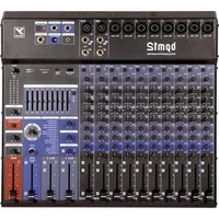
| Model | PGM8 |
| Dimensions (W x D x H) | 36 x 32.5 x 7 cm |
| Weight | 3.8 kg |
| Power supply | 100-240 V AC, 50/60 Hz, universal switching power supply |
| Consumption | 26 VA typical |
| Microphone inputs (XLR) | 6 balanced inputs with switchable 48V phantom power |
| Line inputs (6.35 mm jack) | 6 balanced inputs (1 high impedance for guitar) |
| RCA inputs | 1 unbalanced stereo pair (Media In) |
| Main outputs | Balanced XLR (rear panel) and TRS jack (front panel) |
| Monitor output | TRS jack (front panel) |
| Effects output (EFX Send) | TRS jack (front panel) |
| Headphone output | 6.35 mm stereo jack |
| Recording outputs | 1 stereo RCA pair |
| Equalization | 3-band per channel (+/-15 dB) + main stereo 7-band graphic equalizer |
| Digital effects | 24-bit, 16 presets (reverb, echo, chorus, flange, etc.) |
| Compressor | Built-in Soft-Knee on mono channels |
| High-pass filter | 80 Hz, 18 dB/octave (switchable per channel) |
| VU meter | 2 x 10 segment LED (post main EQ) |
| Construction | Steel chassis |
| Included accessories | Power cord, user manual |
| Care and cleaning | Clean with a dry cloth only. Keep the box for possible return. |
| Safety | Do not expose to water or moisture. Disconnect during storms. Indoor use only. |
| Spare parts and repairability | No user-serviceable parts. Consult a qualified technician. |
Frequently Asked Questions - PGM8 YORKVILLE
User questions about PGM8 YORKVILLE
0 question about this device. Answer the ones you know or ask your own.
Ask a new question about this device
Download the instructions for your Hand blender in PDF format for free! Find your manual PGM8 - YORKVILLE and take your electronic device back in hand. On this page are published all the documents necessary for the use of your device. PGM8 by YORKVILLE.
USER MANUAL PGM8 YORKVILLE
OWNER'S MANUAL
MANUEL DE L'UTILISATEUR
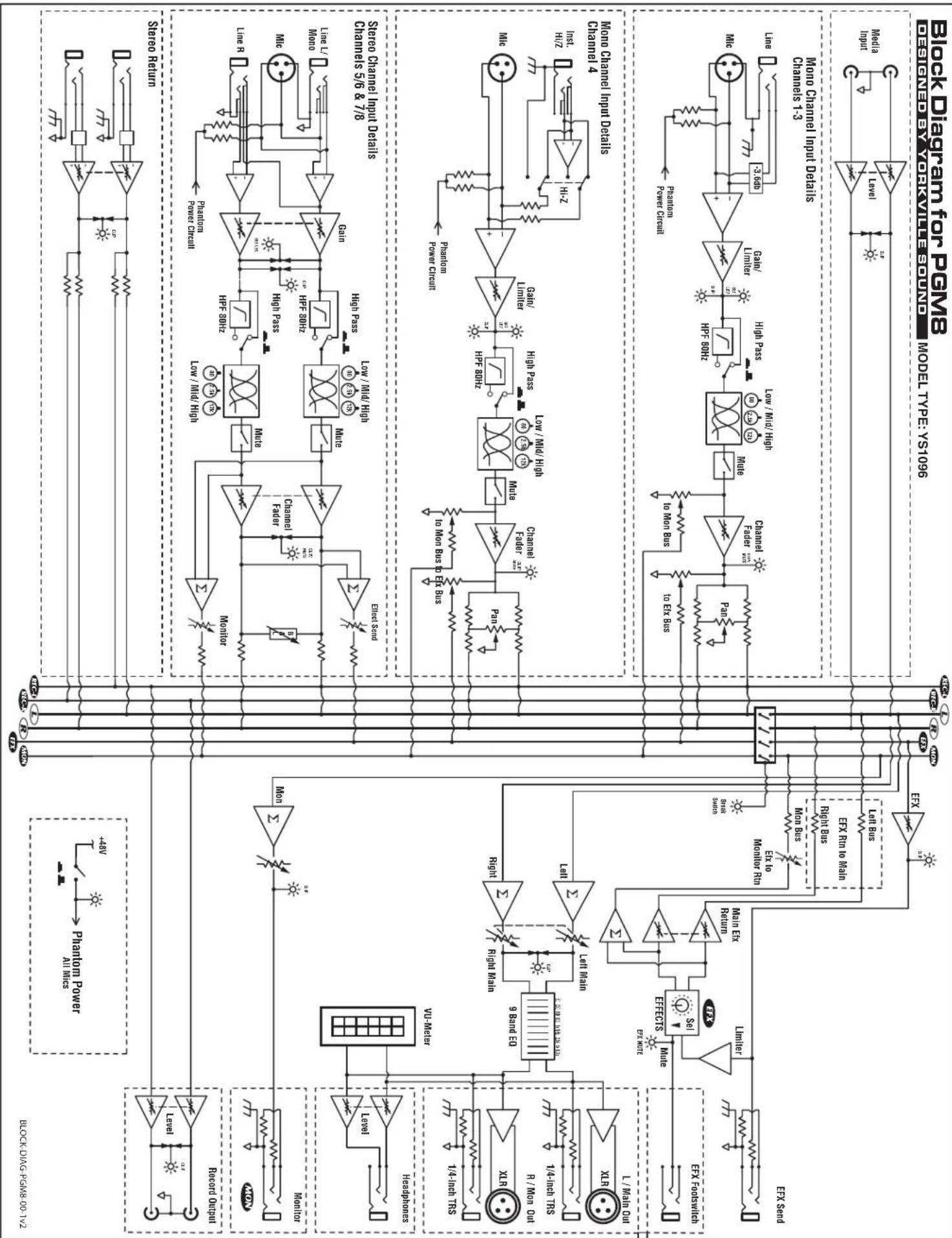
TYPE: YS1096
IMPORTANT SAFETY INSTRUCTIONS

This lightning flash with arrowhead symbol, within an equilateral triangle, is intended to alert the user to the presence of uninsulated "dangerous voltage" within the product's enclosure that may be of sufficient
magnitude to constitute a risk of electric shock to persons.
The exclamation point within an equilateral triangle is intended to alert the user to the presence of important operating and maintenance (servicing) instructions in the literature accompanying the appliance.

Instructions pertaining to a risk of fire, electric shock, or injury to a person
CAUTION: TO REDUCE THE RISK OF ELECTRIC SHOCK, DO NOT REMOVE COVER (OR BACK).
NO USER SERVICEABLE PARTS INSIDE.
REFER SERVICING TO QUALIFIED SERVICE PERSONNEL.
THIS DEVICE IS FOR INDOOR USE ONLY!
Read Instructions: The Owner's Manual should be read and understood before operation of your unit. Please, save these instructions for future reference and heed all warnings.
Clean only with dry cloth.
Packaging: Keep the box and packaging materials, in case the unit needs to be returned for service.
Warning: To reduce the risk or fire or electric shock, do not expose this apparatus to rain or moisture. Do not use this apparatus near water!
Warning: When using electric products, basic precautions should always be followed, including the following:
Power Sources
Your unit should be connected to a power source only of the voltage specified in the owners manual or as marked on the unit. This unit has a polarized plug. Do not use with an extension cord or receptacle unless the plug can be fully inserted. Precautions should be taken so that the grounding scheme on the unit is not defeated. An apparatus with CLASS I construction shall be connected to a Mains socket outlet with a protective earthing ground. Where the MAINS plug or an appliance coupler is used as the disconnect device, the disconnect device shall remain readily operable.
Hazards
Do not place this product on an unstable cart, stand, tripod, bracket or table. The product may fall, causing serious personal injury and serious damage to the product. Use only with cart, stand, tripod, bracket, or table recommended by the manufacturer or sold with the product. Follow the manufacturer's instructions when installing the product and use mounting accessories recommended by the manufacturer. Only use attachments/accessories specified by the manufacturer
Note: Prolonged use of headphones at a high volume may cause health damage on your ears.
The apparatus should not be exposed to dripping or splashing water; no objects filled with liquids should be placed on the apparatus.
Terminals marked with the "lightning bolt" are hazardous live; the external wiring connected to these terminals require installation by an instructed person or the use of ready made leads or cords.
Ensure that proper ventilation is provided around the appliance. Do not install near any heat sources such as radiators, heat registers, stoves, or other apparatus (including amplifiers) that produce heat.
No naked flame sources, such as lighted candles, should be placed on the apparatus.
Power Cord
Do not defeat the safety purpose of the polarized or grounding-type plug. A polarized plug has two blades with one wider than the other. A grounding type plug has two blades and a third grounding prong. The wide blade or the third prong are provided for your safety. If the provided plug does not fit into your outlet, consult an electrician for replacement of the obsolete outlet. The AC supply cord should be routed so that it is unlikely that it will be damaged. Protect the power cord from being walked on or pinched particularly at plugs. If the AC supply cord is damaged DO NOT OPERATE THE UNIT. To completely disconnect this apparatus from the AC Mains, disconnect the power supply cord plug from the AC receptacle. The mains plug of the power supply cord shall remain readily operable.
Unplug this apparatus during lightning storms or when unused for long periods of time.
Service
The unit should be serviced only by qualified service personnel. Servicing is required when the apparatus has been damaged in any way, such as power-supply cord or plug is damaged, liquid has been spilled or objects have fallen into the apparatus, the apparatus has been exposed to rain or moisture, does not operate normally, or has been dropped.
NSTRUCTIONS
Introduction
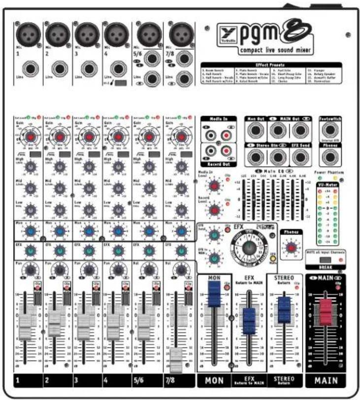
Welcome to the PGM8. A compact versatile low noise audio mixer designed for use in small to medium size clubs, churches, corporate events, and in home studios. Ideal for use with powered loudspeakers, the PGM8 includes these features:
- A Simple soft audio compressor on the mono channels providing a better mix
- Set Level LEDs on channel inputs for easy Channel Gain adjustment
- A switchable hi-impedance guitar input
• 48-volt phantom power - Onboard 24-bit digital effects with 16 versatile presets
• Audio compression on the internal effects send for cleaner digital effects - Stereo graphic equalizer
- Break switch mutes all input channels
- Mute switch on all input channels
- Clip LEDs on all critical signal inputs and outputs
• Balanced XLR and T.R.S. phone jack outputs
• Universal switching power supply operates on 100 to 240 volts AC
This manual explains the various functions. Realizing that some PGM8 users may be unfamiliar with certain features, user tips and additional information is included, appearing separately in the applicable sections.
For general information about mixing and other facets of sound-reinforcement check out our P.A. User Guide available on the internet... (http://www.yorkville.com).


Input Channel Features
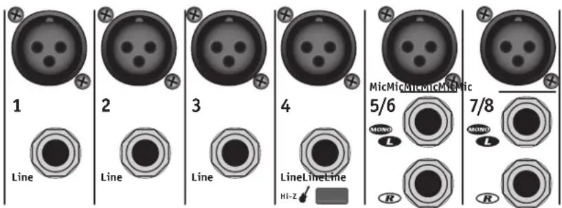
1. Microphone Inputs
All mono and stereo input channels have microphone XLR inputs. These microphone inputs are balanced for maximum noise suppression. The PGM8 active input circuitry accepts microphones with impedances ranging from 50 ohms through 10,000* ohms. All low impedance microphones are compatible. Phantom power (covered in the Rear Panel section of this manual) is available on all Mic inputs when activated. This feature is for condenser microphones but you can also connect dynamic microphones without any problems.
*Although it would be customary to plug high impedance microphones into the Line jacks, most of them will also work in the Mic inputs, provided the microphone's built-in XLR connections are wired with the audio signal on pin 2 and pin 3 is connected to pin 1.
2. Balanced Line Inputs
Mono line-level sources, such as guitar amplifier line-level outputs, keyboards, and hi-impedance microphones, connect to the mono or stereo channels through the line input jacks. The Left and Right Line inputs on the stereo channels are wired internally so that a single (mono) signal connected to the L/Mono input will also be patched over to the Right input (as long as a phone plug is not plugged into the Right jack). This simplifies connecting a mono source, should the need arise (in the situation where all the mono channels are taken).
You can connect stereo audio sources such as a digital audio player, CD-player, MP3 player or tape deck to the Line inputs on the stereo channels. Use RCA to phone plug adapters to connect RCA cables to the Line inputs. It is possible to connect stereo sources to the mono channels, however you will need to plug the L&R signals into separate channels to avoid the risk of inter-modulation distortion. The inter-modulation distortion may be caused by using a "Y" connector to combine the left and right signals into a single Line jack. If you connect a stereo source to two mono channels don't forget to adjust the Pan controls so that one is set to L and the other is set to R. this will make sure that the left and right music signals remain separate.
Channel 4 has a very high impedance, unbalanced 14 -inch input which is optimized for instruments such as acoustic electric guitars. Push the Hi-Z switch in to change channel 4 to a high impedance input.

1/4-inch Phone Plug

1/4-inch T.R.S. Phone Plug

XLR Plug
The balanced connector wiring is:
Tip (or XLR pin 2) = hot, in phase;
Ring (or XLR pin 3) = hot, reverse phase;
Sleeve (or XLR pin 1) = ground
You can connect an unbalanced source to the Line inputs with a standard unbalanced shielded patch cable without any adverse affects.
A slight modification to a balanced patch cable will help achieve noise cancellation when connecting the PGM8 to an unbalanced unit. Simply modify one end of a balanced patch cord and de-solder the wire from the ring tab, then resolder the wire to the
Gain Control
Channel Fader

shield tab making sure that it does not touch anything else. Now re-assemble the plug and mark it with some tape for future reference. This will be the end that you plug into the unbalanced music source (this will also work with an RCA connector).
For best performance when connecting turntables, a phono RIAA pre-amplifier must be used to connect to the PGM8 inputs.
Connecting signals to both types of inputs on any one channel (MIC and LINE in) is NOT recommended. To do so may change the gain of the input circuit.
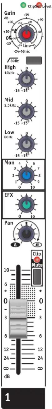
3. Gain Control
PGM8 features active channel input circuitry with exceptionally high audio headroom. The Gain control adjusts the input gain level to match it with the input audio signal level. There are two gradation circles on the gain control. The outer one (-24 dB to +60 dB) is the gain for the Mic Input, the inner one (-36 dB to +45 dB) is for the Line input. Since this control has a range of 84 dB, it presents the user with a wide range of gain control.
Here's a quick way during a sound check to ensure that the Gain is adjusted correctly for the highest headroom and lowest noise. First turn the Channel Fader to the infinity symbol. With a music source playing into the mixer's channel turn the Gain control clockwise until the Set Level LED begins to flash. Having the Set Level LED flashing shows you that you have the optimum gain setting for the music level on that channel input. Having the Set Level LED remain on continuously indicates that you should turn down the Gain control until the Set Level LED is flashing. Having the Set Level LED remain on continuously indicates that the input audio compressor is active. Now turn up the Channel Fader to the desired audio level for the overall music mix. How to use the input audio compressor is explained below.
The PGM8's Clip LED will turn on at 3 dB below the onset of actual clipping. It is acceptable to have this LED flash occasionally during music peaks. You will find that this or any audio system performs with less distortion and less noise when the gain controls are all set properly.
4. Input Channel Audio Compressor
Each of the mono input channels of the PGM8 (channels 1-4) have an internal dual-slope soft-knee audio compressor. The PGM8's compression function is suitable for bass guitars, percussive sources, and vocals.
A compressor reduces the dynamic range of the music providing a more constant level. Like having a sound engineer dynamically adjusting the gain of each channel for the optimum audio level.
The PGM8 compressor works automatically in the background. It can reduce clipping of the audio signal during loud passages in the music, or adjusted by the user providing a tighter sound typically heard in audio recordings. You can adjust how much compression you want with the input channel Gain control.
Here's how to use the compressor. In automatic mode, set the Gain level so that the Set Level LED is just blinking to the music. The compressor will remain off until someone yells into the microphone or there is a loud percussive sound then the compressor will reduce the gain reducing the possibility of clipping. To adjust for little to no compression, have the music source playing into the input channel. Turn up the input channel Gain control to the point where the Set Level LED is just blinking with the music. At this point the full dynamic range of the music source will be experienced. Continuing to turn the input channel Gain control clockwise, the music will get louder. To maintain the same audio level turn down the Channel Fader for the channel being adjusted. The further the input channel Gain control is turned clockwise, or the louder the music source becomes, the greater the compression will be experienced.
If the Clip LED blinks occasionally then the maximum amount of compression has been reached. If the Clip LED remains on for longer periods, turn down the Gain level until the Clip LED blinks occasionally.


5. High Pass Filter Button
Situated at the top of the channel strip this switch activates a High-Pass Filter (a bass roll-off of 18 dB per octave below 80 Hz).
The HPF (High-Pass Filter) is useful for controlling unwanted low-frequency spillover picked up by microphones located too close to the bass drum, bass amp or the keyboard amp. It is also effective in optimizing acoustic guitar pickups that sound boomy from the guitar body resonance (the lowest note on a concert-tuned guitar is 81.2 Hz, so you aren't losing anything by rolling off the input response below 80 Hz). Additionally, the HPF works to reduce breath pops and wind noise from vocal microphones. Any microphone, or pickup, connected to a source that does not go below 80 Hz should have the HPF activated. This includes most wind instruments, most male voices, nearly all female voices and all drum microphones except for the kick-drum.
Why roll off the bass on these channels? ...Because you will get better sound clarity and improve the system's gain before feedback.
6. Channel EQ
The mono and stereo channels feature 3-band Equalization with a control range of +/-15dB. The High EQ is shelving at 12,500 Hz, Low EQ shelves at 80 Hz, and the Mid EQ is centered at 2500 Hz. The tone control frequencies were carefully selected to help achieve the best quality of sound.
It is best to set the channel EQ during a sound check. The less you adjust the EQ controls above (called "boost") or below (called "cut") the centre 0 position the better as +/-15dB represents a considerable level change.
For vocals turning the Low control counterclockwise will reduce the boominess of male voices. For male or female vocals it will also "clean up" the mix as this channel will reduce the bass sound from instruments heard by this microphone.
The Mid is a very powerful control because adjusting it will affect any music source. If a vocal or instrument sounds "honky" you typically "cut," or turn the Mid control counter clockwise, to reduce the mid frequencies. This produces a more pleasant sound.
Symbols can sound hotter, or an instrument can sound brighter, when you boost the High control. Only add a little boost, as too much boost can be the cause of squealing feedback. Cutting the High control can reduce the hiss coming from some audio sources, and can also make some bass instruments sound warmer.
The center position of the tone control reflects a neutral or flat EQ control setting; however, turning down EQ settings can be used effectively to reduce feedback and/or distortion).
7. Mon (Monitor)
The Mon (Monitor) is the audio signal for the stage monitors for the musicians. This control adjusts the level of signal from each channel to the MON fader. The signal for the Mon control is independent of the Channel Fader. Adjusting the Channel Fader will not affect your monitor mix.
When feedback occurs, the cause is often the music from the stage monitors getting back to the microphones. When this happens, the first thing to do is turn down the Mon fader to make sure that the monitors and not the main P.A. is the cause of the feedback. If the cause is the monitors follow these steps:
i. Turn up the MON fader until feedback is just starting.
ii. Now turn down each channel's MON control just a little then return the control back to the original position. Which control reduced the feedback the most?
iii. Take that control and reduce the level to the point of no feedback. By using the MON control you'll eliminate the feedback without affecting that channel's level through the main P.A.

With the PGM8's independent monitor mix, it can be beneficial to connect a graphic equalizer between the MON output and the monitor amplifier (external amplifier or powered speakers, depending on how you have it set up) and use the graphic equalizer to control feedback.
8. Digital Effects (EFX)
The channel EFX control adjusts the level of signal from each channel to the EFX Send control. The signal for the EFX control comes from the Channel Fader. Adjusting the Channel Fader will change the level of the dry signal and the EFX signal. The signal from the EFX Send control continues to the internal effects generator, and to the EFX Send jack for use with an external effects unit.

Alternatively, if you do not require any effects at all, the signal at the EFX Send jack can connect to the input of an additional monitor system or another amp/speaker system via the EFX Out jack using a standard balanced patch cord. In this case, the EFX controls would act as send controls to achieve a semi-separate mix. Remember that the Channel Fader level controls also affects this signal.
9. Pan Control (Mono Channels)
This controls the post Channel Fader signal routing to the Main fader through the main bus. In the Pan Control, the signal levels are compensated at the L&R rotation extremes so that panning during a performance will result in minimal sound level change in the center-field audience areas.

In audio terminology, a bus is a mix-down channel where all the signals from the input channels are blended into one signal. The PGM8 has 5 busses: MAIN (left and right), MONITOR, EFFECTS and RECORD OUT
10. Balance Control (Stereo Channels)
This controls the stereo channel signal routing to the Main Fader. Similar to the Pan Control, the Balance Control can shift the center image between the left and right channels.
11. Mute Switch
Each channel's Mute Switch mutes that channel's left, right, and all of its sends signals. The Mute function is a timesaving feature that enables you to mute channels without turning down the Channel Fader that you preset during the sound check.
It's important to mute all unused channels during a performance as open microphones increase the possibility of feedback, and can made a music mix sound muddy.

12. Clip/Mute LED
The Clip LED turns on at 3 dB below the channel's actual clipping level and with the Clip LED threshold set below actual clipping level, it is possible to allow occasional light activity without worrying about distortion. As a result, you may use the Clip LED to help you adjust the proper gain with the Channel Fader control. When the Mute switch is depressed, the Clip LED will illuminate at half-brightness to indicate the mute condition but will still flicker to indicate clipping.
13. Channel Fader
The Channel Fader control's taper is expanded in the upper mid-slide area for precise volume adjustments and condensed at the extremes allowing you to increase or decrease the audio level quickly. The audio out of the Channel Fader goes simultaneously to the channel EFX, and Pan controls.
Master Section
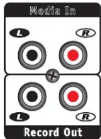
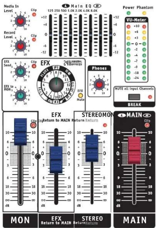
1. Media Input
The Media In unbalanced RCA jacks accept signals from computers, CD players, MP3 players, or any other audio playback device. The Media In level control allows you to adjust the incoming audio level. If the Media In Clip LED illuminates turn the Media In level control down until the LED is not on.
The audio from the Media In level control goes directly to the Main fader. Pressing the Break switch will mute all of the input channels except for the Media In so that the audio passing through the Media Input can play when the band is on "break."
2. Record Outputs
In traditional mixers the record audio signal branches off after the Main fader which can result in a low level record audio signal. The problem is that the audio level is not large enough to reach 0 dB on your recording device level meters. Unlike traditional mixers, the PGM8 has a separate audio buss connecting all of the input channels, Media In, and the Stereo Return to the Record Level control. Using the Record Level control you can set the Record Out level for 0 dB on your recording device level meters for optimum headroom and minimum noise.
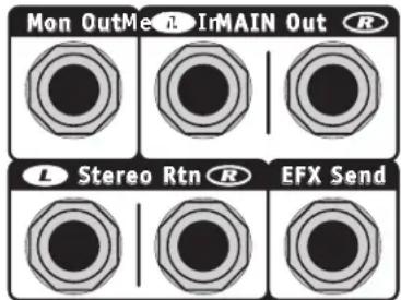

3. EFX Send Control
Audio signals from each channel EFX level control arrive at the EFX Send level control. From the EFX Send control the audio signal arrives at the EFX Send phone jack on the front panel, and also arrives at the internal digital effects generator.
To get started, figure out which channels you want effects on (e.g. vocals, lead guitar, brass instruments, and keyboards - most likely not on the drums or the bass guitar). During a sound check, turn up the EFX Send control to level 5. On the channels that you want effect turn the EFX control up about halfway at first and turn up the Channel Faders to about 0dB. Now dial in one of the sixteen desired effects – the menu of presets is located at the top of the mixer.
Next, turn up the EFX Return to MAIN fader (main system) to 0 dB. Now turn up the MAIN fader to a moderate listening level. You can re-adjust the EFX Return to MAIN control to increase or decrease the effect's intensity in the main mix. Like the EFX Return to MAIN control, there is an EFX to MON control to add some effects to the monitor signal.
4. Internal Digital Effects Generator
The PGM8 has an onboard 24-bit digital effects generator with 16 versatile presets. Use the EFX selection control to choose from the 16 reverbs, echos, chorus, flange, or rotary speaker. There is even an acoustic guitar effect to enhance the audio from an acoustic guitar piezo pick-up.
| Effect Presets | |||
| 1. Room Reverb2. Hall Reverb3. Hall Reverb - Vocals4. Hall Reverb w/Echo | 5. Plate Reverb6. Plate Reverb - Vocals7. Plate Reverb w/Echo8. Gated Reverb | 9. Fast Echo10. Short Decay Echo11. Long Decay Echo12. Chorus | 13. Flanger14. Rotary Speaker15. Acoustic Guitar16. Harmonizer |
Like the audio compressor on the input channels there is an audio compressor controlling the signal to the internal effects generator. This compressor acts like an automatic gain circuit making sure that the optimum audio signal enters the internal effects generator. If the EFX Send Clip LED blinks occasionally then you have the maximum amount of compression. If the Clip LED remains on for longer periods then you should turn down the EFX Send level until the LED blinks occasionally.
It is possible to use the internal digital effects and an external effects unit at the same time. You can set one effects unit for reverb, and the other unit for a special effect not used often like echo. Connect a cable from the EFX Send jack to the input of your effects unit. Then connect a cable from the output of your effects unit into the Stereo Return jacks. You will use the Stereo Return fader to control the level of the external effects.
5. Footswitch Jack
Connect a standard footswitch to the Footswitch jack to switch the internal effects on and off. The EFX Mute LED will illuminate when the internal effects are muted ('off') by the Footswitch. Only use a TRS (Tip, Ring, Sleeve) cable
6. MON Fader
Audio signals from each channel MON level control arrive at the MON fader. The MON fader adjusts the level of each channel's signal into the monitor mix. From the MON fader the audio signal arrives at the MON output phone jack on the front panel. The shaded area on the MON fader front panel graphic is the fader's usual operating position. If the MON fader's knob is up at 10 or down at -18 you may want to check the position of the channel Gain or Mon controls to be sure that they are not turned to the extreme of their setting range.
7. MAIN Fader
Audio signals from each channel Pan level control arrive at the MAIN fader. The MAIN fader adjusts the level of each channel's signal onto the main mix. From the MAIN fader the audio signal passes through the Main EQ to the MAIN Out phone jacks on the front panel and to the MAIN Out XLR jacks on the rear panel. The shaded area on the MAIN fader front panel graphic is the fader's usual operating position. If the MAIN fader's knob is up at 10 or down at -30 you may want to check the position of the channel Gain or Channel Fader controls to be sure that they are not turned to the extreme of their setting range.
To ensure maximum signal head room and clarity, set the channel Gain and Fader controls first for a good signal without clipping, then set the master for the overall volume desired.


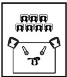
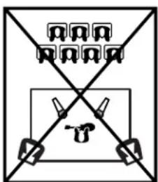
natural_image
Simple line drawing of a face with arrows pointing at top and bottom (no text or symbols)Keep the Main Speakers between mics and audience to minimize feedback
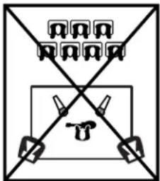
DO NOT place Main Speakers in back of the stage!!
8. L/R Main EQ
This is a stereo 7-band EQ on the output of the MAIN fader. The EQ's adjustment range is +/-12 dB with frequency centers at one-octave intervals from 125 Hz to 8 kHz.
Use the Main EQ during a sound check to carefully adjust the main speaker response (you shouldn't have any radical boosts). It is also useful for minimizing feedback, but remember that stage monitor speakers are most often the cause of your feedback problems. Naturally, stage monitor feedback will also be heard out the main speakers at the mixer station, which can lead you to the illusion that the main system is the cause.
When setting the Main EQ, do not automatically go to a smiling curve as with a home stereo – this will cost your system both headroom and gain before feedback. Initially, keep the EQ curve as close to flat (all sliders at center) as possible, then make necessary minor adjustments as required during the sound check to cut feedback frequencies. When feedback is heard first turn down the MON fader. To reduce the possibility of the main speakers causing the feedback cautiously turn up the Main fader to the onset of feedback. Try to guess the frequency of the ringing tone. Reduce the Main EQ fader closest to the frequency of the feedback. You should only need to reduce the fader to about -3dB on the front panel EQ scale. Cautiously turn up the Main fader a little more to the onset of feedback. Try to guess the frequency of the 2nd ringing tone which will most likely be different than the first feedback frequency. Reduce the Main EQ fader closest to the frequency of the feedback. Again you should only need to reduce the Main EQ fader to about -3dB on the front panel EQ scale.
Typically there are about three major feedback frequencies that you can compensate for with the Main EQ. Now with the main fader placed in your performance gain position slowly turn up the MON fader to obtain enough monitor volume without causing feedback.
9. Phones Level
The Phones level control adjusts the stereo audio level to the headphones plugged into the Phones jack. The audio signal for the headphones is post Main EQ so that you can hear exactly the audio signal on the Main Out phone and Main Out XLR jacks.
The Phones (headphones) jack is a stereo jack compatible with headphones having an impedance down to 8 ohms but we recommend for best performance using headphones with an impedance of 80 ohms or higher.
10. Break Switch
The Break switch is a great feature. When the Break switch is pressed on and the Break LED is blinking the audio signals from channels 1 to 8 are muted. While the Break switch is on you can play music through the Media In jacks. Great for when the band goes on break, or while showing a video during a presentation muting room noise picked up by the vocal microphones.
11. VU-Meter
The VU-Meter indicates the post Main EQ left and right audio levels. A good operating level is when the music peaks light up the 0dB LEDs. Having the yellow +3dB and +6dB LEDs flash occasionally is acceptable but you do not want the red +10dB LEDs coming on as this indicates the possibility of clipping.
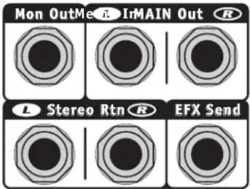
Top Panel Output Jacks
The Main Out, Mon Out and EFX Send phone jacks on the top panel are TRS (balanced tip ring sleeve configuration) output jacks. Use them to connect to balanced and unbalanced audio inputs.
The Stereo Rtn jacks are TRS balanced input jacks. You can connect to the balanced or unbalanced outputs of audio equipment.
The Phones (headphones) jack is a stereo jack compatible with headphones with an impedance down to 8 ohms but we recommend for best performance using headphones with an impedance of 80 ohms or higher.
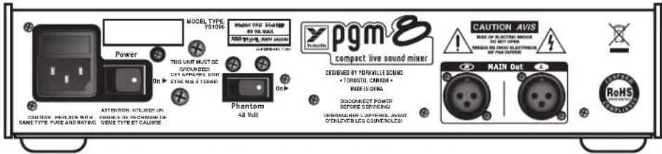
Rear Panel
1. Power Switch and Fuse
The power switch is located on the rear panel. It is unlikely that the fuse would blow but if there is the suspicion that the fuse has blown first:
i. Confirm that there is 120VAC/230VAC at the point where the PGM8 power plug connects to either a wall plug or an extension cord.
ii. Confirm that the power switch is turned on.
iii. If the PGM8 Power LED is still off disconnect the AC power cord from the PGM8.
iv. Use a screwdriver to slide out the fuse drawer located on the IEC AC power socket of the PGM8.
v. If visually you can see that the fuse is blown replace with the same type 500mAL sloblo type fuse. It is very important to replace the fuse with exactly the same type of fuse.
vi. If when powering up the PGM8 with the new fuse the fuse blows again then your PGM8 may require service from an authorized service technician.
2. Phantom Power Switch
Phantom Power is available for condenser microphones. Even though dynamic microphones do not need phantom power, having the phantom power turned on will not harm dynamic microphones. When connecting microphones it is safest to turn off the phantom power to avoid loud pops. The Phantom Power switch is located on the rear of the mixer. Beside the Power LED the Phantom Power LED is in the upper right area of the control panel.
To obtain the best performance from your condenser microphones 48 Volt Phantom Power is available on channels 1 through 8.
3. Main Out XLR Jacks
The main out left and right XLR jacks are located on the rear panel. These are true low impedance balanced outputs. For the best noise immunity use well shielded XLR cables.
Input Wiring tips:
- For all input connectivity use shielded wire only. Cables with a foil shield or a high-density braid are best.
- When changing input connections, turn down the level controls on the mixer to eliminate pops and thumps out of the loudspeakers.
- Keep input connection cables as short as possible to minimize noise and hum.

pgm&
compact live sound mixer
SPECIFICATIONS
Number of Channels 8
Mono Channel EQ 3-band
Balance Controls Yes
Pan Controls Yes
Channel Overload Protection Yes
Inputs - XLR (bal) 6
Inputs - 1/4-inch 6
Inputs - RCA (unbal) 1 stereo pair
Phantom Power 48 volt + LED indicator
VU Meter 2 x 10 Segment LEDs
Headphone Monitor Features yes
Internal Effects 24 bit stereo 16 effects
Effects Send 2 (1 internal, 1 external)
Effects Return to Main yes
Effects Return to Monitor yes
Reverb / Effects Footswitch yes
Record Outputs 1 stereo pair
Mixer - Signal to Noise Ratio (dB) Greater Than -100dB
Mixer - Frequency Response (Tone and EQ Flat,+/-2dB) 20Hz - 20KHz
Mixer THD (Main out w/ -10dB input) Less Than 0.05%
Typical crosstalk -1 kHz (dB) Greater Than -60dB
CMRR @ 60Hz (min/typ) 55dB/65dB
Power Consumption (typ/max) 26VA (typical)
Chassis Construction Steel
Dimensions (DWH, inches) 14.2 x 12.8 x 2.8
Dimensions (DWH, cm) 36 x 32.5 x 7
Weight (lbs/kg) 8.5/3.8
* Specifications subject to change without notice
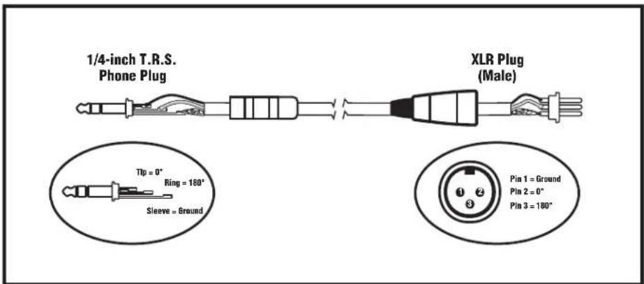
Balanced 1/4-inch T.R.S. to Balanced XLR
Introduction.

1/4-inch T.R.S. Phone Plug

XLR Plug

3. Commande EFX Send
| 1. Room Reverb2. Hall Reverb3. Hall Reverb - Vocals4. Hall Reverb w/Echo | 5. Plate Reverb6. Plate Reverb - Vocals7. Plate Reverb w/Echo8. Gated Reverb | 9. Fast Echo10. Short Decay Echo11. Long Decay Echo12. Chorus | 13. Flanger14. Rotary Speaker15. Acoustic Guitar16. Harmonizer |
natural_image
Simple line drawing of a mechanical or electrical component with no text, numbers, or symbolsKeep the Main Speakers between mics and audience to minimize feedback
DO NOT place Main Speakers in back of the stage!!
8. EQ Principal G et D
3. Main Out XLR Jacks.
SPÉCIFICATIONS
Nombre de canal 8
EQ Canal Mono 3 bandes
Balanced 1/4-inch T.R.S. to Balanced XLR

flowchart
graph TD
    A["Input"] --> B["FX Sand"]
    B --> C["EX Rx Tin to Main"]
    C --> D["FX Rlm to Main"]
    D --> E["Ex to Monitor Rlm"]
    E --> F["Main Ex"]
    F --> G["EffectS"]
    G --> H["9 Band ED"]
    H --> I["Left Main"]
    I --> J["Right Main"]
    J --> K["Vu-Meter"]
    K --> L["Record Output"]
    L --> M["Monitor"]
    M --> N["Headphones"]
    N --> O["XLR"]
    O --> P["R/Mon Out"]
    P --> Q["T/4-Inch TRS"]
    Q --> R["XLR"]
    R --> S["T/4-Inch TRS"]
    S --> T["Headphones"]
    T --> U["LED"]
    U --> V["Level"]
    V --> W["Radio"]
    W --> X["Main Ex"]
    X --> Y["EffectS"]
    Y --> Z["9 Band ED"]
    Z --> AA["Left Main"]
    AA --> AB["Right Main"]
    AB --> AC["Vu-Meter"]
    AC --> AD["Record Output"]
    AD --> AE["Monitor"]
    AE --> AF["XLR"]
    AF --> AG["T/4-Inch TRS"]
    AG --> AH["XLR"]
    AH --> AI["T/4-Inch TRS"]
    AI --> AJ["Headphones"]
    AJ --> AK["LED"]
Two & Ten Year Warranty
Two & Ten
Unlimited Warranty
Yorkville's two and ten-year unlimited warranty on this product is transferable and does not require registration with Yorkville Sound or your dealer. If this product should fail for any reason within two years of the original purchase date (ten years for the wooden enclosure), simply return it to your Yorkville dealer with original proof of purchase and it will be repaired free of charge. This includes all Yorkville products, except for the YSM Series studio monitors, Coliseum Mini Series and TX Series Loudspeakers.
Freight charges, consequential damages, weather damage, damage as a result of improper installation, damages due to exposure to extreme humidity, accident or natural disaster are excluded under the terms of this warranty. Warranty does not cover consumables such as vacuum tubes or par bulbs. See your Yorkville dealer for more details. Warranty valid only in Canada and the United States.
Garantie Illimitée
Voice: (905) 837-8481 Voice: (716) 297-2920
Fax: (905) 837-8746 Fax: (716) 297-3689

www.yorkville.com
Yorkville Sound
550 Granite Court
Pickering, Ontario
L1W-3Y8 CANADA
Yorkville Sound Inc.
4625 Witmer Industrial Estate
Niagara Falls, New York
14305 USA

natural_image
World map illustration with horizontal black lines, no text or labels presentWEB: www.yorkville.com
Niagara Falls, New York
14305 USA
Voice: (716) 297-2920
Fax: (716) 297-3689

Quality and Innovation Since 1963
Printed in China
manual-owners-PGM8-00-1v5 • Dec 14, 2016


- OWNER'S MANUAL
- MANUEL DE L'UTILISATEUR
- IMPORTANT SAFETY INSTRUCTIONS
- Power Sources
- Hazards
- Power Cord
- Service
- NSTRUCTIONS
- Introduction
- Input Channel Features
- Microphone Inputs
- Balanced Line Inputs
- Gain Control
- Channel Fader
- Gain Control
- Input Channel Audio Compressor
- High Pass Filter Button
- Channel EQ
- Mon (Monitor)
- Digital Effects (EFX)
- Pan Control (Mono Channels)
- Balance Control (Stereo Channels)
- Mute Switch
- Clip/Mute LED
- Channel Fader
- Master Section
- Media Input
- Record Outputs
- EFX Send Control
- Internal Digital Effects Generator
- Footswitch Jack
- MON Fader
- MAIN Fader
- L/R Main EQ
- Phones Level
- Break Switch
- VU-Meter
- Top Panel Output Jacks
- Rear Panel
- Power Switch and Fuse
- Phantom Power Switch
- Main Out XLR Jacks
- Input Wiring tips:
- pgm&
- SPECIFICATIONS
- Introduction.
- Commande EFX Send
- EQ Principal G et D
- Main Out XLR Jacks.
- SPÉCIFICATIONS
- Two & Ten Year Warranty
- Unlimited Warranty
- Garantie Illimitée
Brand : YORKVILLE
Model : PGM8
Category : Hand blender