YT-82361 - Electric sander Yato - Free user manual and instructions
Find the device manual for free YT-82361 Yato in PDF.

| Product type | Electric plaster sander |
| Brand | Yato |
| Model | YT-82361 |
| Rated voltage | 18 V DC |
| Rotation speed | 600 to 1200 min⁻¹ |
| Plate diameter | 215 mm |
| Diameter of abrasive discs | 225 / 215 / 210 mm |
| Weight | 3.0 kg |
| Sound pressure level (L_pA) | 87.0 ± 3.0 dB(A) |
| Sound power level (L_wA) | 95.0 ± 3.0 dB(A) |
| Vibration level (ah,AG) | 3.18 ± 1.5 m/s² |
| Protection class | III |
| Protection index (IP) | IP20 |
| Battery type | Li-ion (not included) |
| Battery capacity | 4 Ah (not included) |
| Charger | Not included (model YT-82360 included) |
| Dust extraction system | Yes, with hose and collection bag |
| Extension handle | Yes, adjustable |
| Speed regulator | Yes, rotary |
| Switch lock | Yes, for continuous operation |
| Maintenance and cleaning | Clean with a dry cloth, use compressed air (max 0.3 MPa) for ventilation openings |
| Spare parts and repairability | Use only Yato spare parts; repairs by authorized center |
Frequently Asked Questions - YT-82361 Yato
User questions about YT-82361 Yato
0 question about this device. Answer the ones you know or ask your own.
Ask a new question about this device
Download the instructions for your Electric sander in PDF format for free! Find your manual YT-82361 - Yato and take your electronic device back in hand. On this page are published all the documents necessary for the use of your device. YT-82361 by Yato.
USER MANUAL YT-82361 Yato
NL DRAADLOZE WANDSCHUURMACHINE
GR TPIBE'IO TO'IXOY MΠΑΤΑΡ'ΙΑΣ
natural_image
Exterior view of a handheld industrial measuring tool with attached cable and base (no text or symbols visible)CE
PL EN DE RU UA LT LV CZ SK HU RO ES FR IT NL GR BG
natural_image
Close-up of a hand using a tool to adjust or install a mechanical component, showing no text or symbols.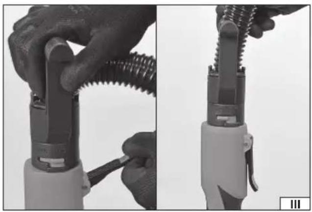
natural_image
Close-up of hands using a coiled tool to adjust or install a mechanical component (no visible text or symbols)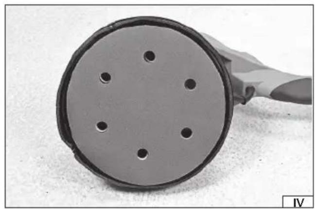
natural_image
Close-up of a cylindrical electronic component with four circular holes, no visible text or symbols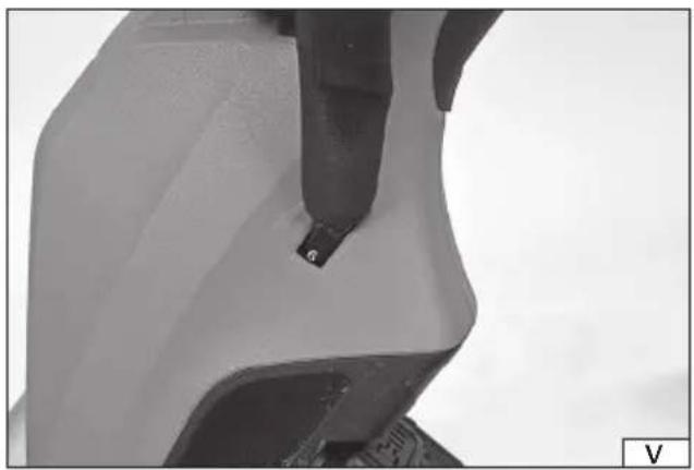
natural_image
Close-up of a mechanical component with a tool inserted, showing a small hole and textured surface (no text or symbols visible)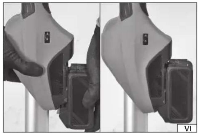
natural_image
Close-up of a robotic device with a hand adjusting its grip, shown from two different angles (no text or symbols visible)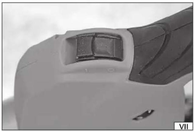
natural_image
Close-up of a mechanical component with a dark square cutout and a black handle, no visible text or symbols.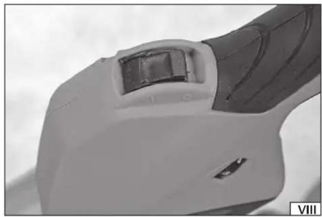
natural_image
Close-up of a mechanical component with a highlighted section and a small inset detail (no visible text or symbols)natural_image
Close-up of a hand using a tool to adjust or install a circular component on a mesh surface (no text or symbols visible)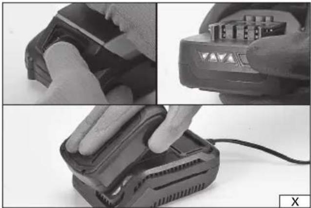
natural_image
Three-panel black-and-white photo showing hands operating a battery pack and charging case, with no visible text or symbols.PL
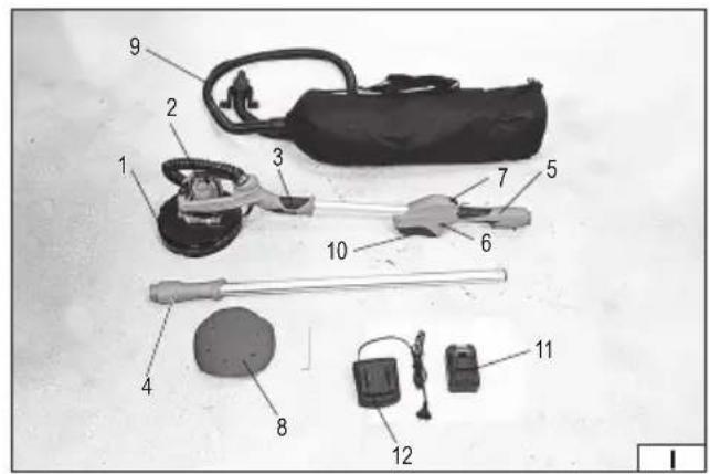
-
disc head
-
drive housing
-
additional handle
-
handle extension arm
-
main handle
-
rotational speed control
-
power switch
-
sanding sheet
-
fl exible hose
-
battery socket
-
battery
-
battery charger
DE
Read the operating instruction
Wear protective goggles
Wear hearing protectors
Always hold the sander with both hands
This symbol indicates that waste electrical and electronic equipment (including batteries and storage cells) cannot be disposed of with other types of waste. Waste equipment should be collected and handed over separately to a collection point for recycling and recovery, in order to reduce the amount of waste and the use of natural resources. Uncontrolled release of hazardous components contained in electrical and electronic equipment may pose a risk to human health and have adverse effects for the environment. The household plays an important role in contributing to reuse and recovery, including recycling of waste equipment. For more information about the appropriate recycling methods, contact your local authority or retailer.
WYPOSAŻENIE PRODUKTU
The gypsum sander is a power tool using sanding discs to sand large, flat surfaces. The long handle allows sanding walls without using any platforms. The sander features a system for the extraction of dust generated during works, and a hose to connect the unit to a vacuum device, which reduces the amount of dust in the work area. The battery power supply allows working in places without easy mains access. Proper, reliable and safe operation of the power tool depends on appropriate use, that is why you should:
Read the entire instructions manual before the first use of the tool and keep it for future reference.
The supplier shall not be liable for any damage resulting from failure to comply with the safety instructions and recommendations specified in this instructions manual.
PRODUCT ACCESSORIES
The tool comes complete but requires some assembly work. The sander comes with sandpaper sheets, dust bag hose and handle extension arm. The YT-82360 article is equipped with a battery and a dedicated charger. The YT-82361 article is not supplied with a battery and charger.
TECHNICAL DATA
| Parameter Unit Value | ||
| Catalogue No. YT-82360, YT-82361 | ||
| Rated voltage [V DC] 18 | ||
| Rated rpm [min] | ^-1 600 – 1200 | |
| Spindle size M6 | ||
| Disc fi xing ring diameter [mm] 215 | ||
| Sanding disc diameter [mm] | 225/215/210 | |
| Weight | [kg] | 3.0 |
| Noise level | ||
| - sound pressure L_pA ± K_pA | [dB (A)] | 87.0 ± 3.0 |
| - power L_wA ± K_wA | [dB (A)] | 95.0 ± 3.0 |
| Vibration level _a0AG ± K | [m/s ^2 ] | 3.18 ± 1.5 |
| Insulation class | III | |
| Protection rating | IP20 | |
| Battery type | Li-ion | |
| Battery capacity* | [Ah] | 4 |
| Charger* | ||
| Input voltage | [V~] | 220 – 240 |
| Mains frequency | [Hz] | 50 / 60 |
| Output voltage | [V DC] 21 | |
| Output current | [A] | 2 |
| Rated power | [W] | 60 |
| Charging time** | [h] | 3 |
* only for models equipped with a battery and charger
** the specified charging time applies only to the battery with the capacity listed in the table
The declared noise emission value has been measured using the standard test method and can be used to compare one tool to another. The declared noise emission value can be used in the preliminary exposure assessment.
The declared total vibration value has been measured using the standard test method and can be used to compare one tool to another. The declared total vibration value can be used in the initial exposure assessment.
Caution! The vibration emission during tool operation may differ from the declared value, depending on the manner the tool is used. Caution! Safety measures to protect the operator, which are based on an assessment of exposure under actual conditions of use (including all parts of the work cycle, such as the time when the tool is switched off or idle and the activation time), must be specified.
GENERAL WARNINGS FOR THE SAFETY OF POWER TOOLS
Warning! Read all safety warnings, illustrations and specifications provided with this power tool. Failure to do so may result in electric shock, fire or serious injury.
EN
Keep all warnings and instructions for future reference.
The term "power tool" used in warnings applies to all tools driven by power both wired and wireless.
Workplace safety
Keep the workplace well-lit and clean. Disorder and poor lighting can be causes of accidents.
Do not work with power tools in an environment with an increased risk of explosion, containing flammable liquids, gases or vapors. Power tools generate sparks that can ignite dust or fumes.
Children and third persons should not be allowed to enter the workplace. Loss of concentration can result in loss of control.
Electrical safety
The plug of the electric cable must match the power socket. You must not modify the plug in any way. Do not use any plug adapters with earthed power tools. An unmodified plug that fits the outlet reduces the risk of electric shock.
Avoid contact with earthed surfaces such as pipes, radiators and coolers. Grounding the body increases the risk of electric shock.
Do not expose power tools to contact with atmospheric precipitation or moisture. Water and moisture that gets inside the power tool increases the risk of electric shock.
Do not overload the power cable. Do not use the power cord to carry, pull or unplug the power plug from the power outlet.
Avoid contact of the power cable with heat, oils, sharp edges and moving parts. Damage or entanglement of the power cord increases the risk of electric shock.
In the case of working outside closed rooms, use extension cords intended for work outside closed rooms. The use of an extension cord adapted for outdoor use reduces the risk of electric shock.
When using a power tool in a humid environment is unavoidable as a protection against supply voltage use a residual current device (RCD). The use of RCD reduces the risk of electric shock.
Personal safety
Stay alert, pay attention to what you do and keep common sense while working with the power tool. Do not use a power tool when you are tired or under the influence of alcohol or medication. Even a moment of inattention while working can lead to serious personal injury.
Use personal protective equipment. Always wear eye protection. The use of personal protective equipment such as dust masks, anti-slip safety shoes, helmets and hearing protection reduce the risk of serious personal injury.
Prevent accidental operation. Make sure that the electric switch is in the “off” position before connecting to the power supply and / or battery, lifting or moving the power tool. Moving the power tool with the finger on the switch or powering the power tool, when the switch is in the “on” position can lead to serious injuries.
Before turning on the power tool remove any keys and other tools that were used to adjust it. The key left on the rotating parts of the power tool can lead to serious injuries.
Do not reach and do not lean too far. Keep the right attitude and balance all the time. This will allow easier control over the power tool in case of unexpected work situations.
Dress accordingly. Do not wear loose clothing or jewelry. Keep your hair and clothing away from moving parts of the power tool. Loose clothing, jewelry or long hair can be caught by moving parts.
If the devices are fitted for the connection of dust extraction or dust collection, make sure that they are connected and used properly. The use of dust extraction reduces the risk of dust hazards.
Do not let the experience acquired from frequent use of the tool resulted in carelessness and ignoring safety rules.
Carefree action can cause serious injuries in a fraction of a second.
Use and care of the power tool
Do not overload the power tool. Use the power tool appropriate for the selected application. The right power tool will provide a better and safer job if used according to the designed load.
Do not use the power tool, if the electric switch does not allow switching on and off. Power tool, which cannot be controlled by means of a power switch is dangerous and must be returned for repair.
Disconnect the plug from the power socket and / or remove the battery if it is detachable from the power tool before adjusting, changing accessories or storing the tool. Such preventive measures will allow you to avoid accidentally turning on the power tool.
Keep the tool out of the reach of children, do not let people who do not know how to operate the power tool or these instructions use a power tool. Power tools are dangerous in the hands of untrained users.
Maintain power tools and accessories. Check the tool for mismatches or jams of moving parts, damage to parts and any other conditions that may affect the operation of the power tool. Damage must be repaired before using the power tool. Many accidents are caused by incorrectly maintained tools.
Keep cutting tools sharp and clean. Properly maintained cutting tools with sharp edges are less prone to jamming and are easier to control when working.
Use power tools, accessories and inserted tools etc. in accordance with these instructions, taking into account the type and conditions of work. The use of tools for work other than designed is likely to result in a dangerous situation.
Handles and gripping surfaces must be dry, clean and free from oil and grease. Slippery handles and gripping surfaces do not allow for safe operation and control of the tool in dangerous situations.
EN
Repairs
Repair the power tool only in authorized facilities using only original spare parts. This ensures proper operation safety of the power tool.
ADDITIONAL SAFETY GUIDELINES FOR DISC GRINDERS AND POLISHING MACHINES
This tool is intended for sanding with sanding paper only. Please refer to all warnings, instructions, illustrations and specifications provided with the power tool. Failure to follow all of the instructions provided below may result in electrocution, fire, and / or serious injury.
Do not convert this tool to make it fit for a job for which it has not been designed and specified by the manufacturer. Such conversion will result in loss of control and cause serious injuries.
It is prohibited to use the tool as a grinder, polisher, wire brush sander, cutter, cutter or in any other manner not compliant with the manual. Performing other works for which the tool is not intended may pose a risk and result in injuries.
Do not use accessories that have not been designed by the manufacturer or intended for the work with the tool. The fact of ability to mount accessories on the tool does not ensure safe operation.
The maximum rotational speed of the accessories must be equal to or greater than the maximum rotational speed of the tool. Accessories with a lower rotational speed than the tool speed can disintegrate into fragments during operation.
The outer diameter and thickness of accessories must be within the size range specified for the tool. It is not possible to properly guard or operate improperly-sized accessories.
The size of the hole used for fixing wheels, discs, flanges, and other accessories must match the size of the tool spindle. Accessories with a fixing hole size not suitable for the tool spindle size will start to vibrate during operation, which may result in the loss of control of the tool.
Do not use damaged accessories. Before each use, examine the condition of the accessories for possible splinters, cracks, abrasions and excessive wear. If any accessories are dropped, make sure they are not damaged, or mount new, undamaged accessories. After checking and installing the accessories, make sure you and all bystanders stand outside the rotation plane of the accessories, then run the tool for one minute at a maximum rotational speed. Damaged accessories will disintegrate during the test.
Wear personal protective equipment. Use face shields, goggles, or safety goggles, depending on the application. If required, use dust masks, hearing protection, safety gloves, and aprons to protect against small pieces of accessories or materials generated during work. The eye protection must be capable of stopping any flying debris generated during work.
The dust mask must be capable of filtering out dust generated during work. Extended exposure to noise can result in hearing loss. Ensure all bystanders keep a safe distance from the work area. Persons entering the work area must wear personal protective equipment. Debris or pieces of damaged accessories which are generated during work can be thrown out of the immediate vicinity of the work area.
When carrying out work during which the disc may come into contact with a live, concealed electrical cable or power cord, hold the sander's insulated handles only. When the disc is in contact with a live wire, it may cause the metal parts of the tool to become live, which may lead to electrocution to the tool operator.
Keep the power cord away from rotating tool parts. If you lose control of the tool, the cord can be cut or caught, and your hand or arm can be drawn into the rotating parts of the machine.
Never put down the tool until the rotating parts have come to a complete standstill. The rotating parts can “catch” the ground and pull the tool out of your control.
Do not turn on the tool while carrying it around. Inadvertent contact with rotating parts can cause your clothes to be caught and pulled in by the tool, which can result in contact with the operator's body.
Clean the tool's ventilation openings regularly. The motor fan draws dust generated during operation inside the tool. Excessive accumulation of metal particles contained in the dust increases the risk of electrocution.
Do not use the tool near flammable materials. Sparks generated during operation may cause a fire.
Do not use accessories requiring liquid cooling. Water or coolant may cause electrocution.
The thread size of the accessories must match the thread of the sander spindle. For flange-mounted accessories, the fixing hole for the accessories must match the size of the fixing flange. Accessories which do not fit into the power tool mount will cause imbalance, excessive vibration and may result in loss of control.
Warnings related to tool kickback towards the operator
The kickback of the tool towards the operator is a sudden reaction to a blocked or clamped: rotating disc, polishing belt, brush or other accessory. Blocking or clamping causes a rotating accessory to stop suddenly, which results in the power tool rotating in the opposite direction to the accessory rotation.
For example, if the grinding wheel is blocked or clamped by the workpiece, the edge of the disc that enters the clamping point may sink into the surface of the material causing the disc to come out or be ejected.
The disc can also be ejected towards or away from the operator, depending on the direction of the grinding wheel movement at the jamming point. Grinding wheels may also break in these conditions.
The tool kickback towards the operator is a result of misuse or failure to follow the guidelines in the manual. This phenomenon can
EN
be avoided by following the instructions below.
Use a firm grip on the tool and the correct body posture and hands position to withstand the forces generated by the kickback. Always use an additional handle, if supplied with the tool, to ensure maximum control during the kickback or any unexpected rotation during the tool start. The operator will be able to control the tool rotation or the kickback if appropriate precautions are taken.
Keep your hands away from rotating tool parts. The rotating parts can come into contact with your hands during kickback.
Do not stand in the area where the tool may move during the kickback. The kickback will direct the tool in the opposite direction to the direction of the grinding wheel rotation, at the jamming point.
Pay special attention when working near corners, sharp edges, etc. Prevent the grinding wheel from runout and being jammed. When machining corners or edges, there is an increased risk of the grinding wheel jam, leading to a loss of control or tool kickback.
Do not use discs with a cutting chain for wood processing, segmented diamond discs with circumferential spacing between segments greater than 10 mm or discs with teeth. Such discs cause frequent kickbacks and loss of control of the tool.
Warnings related to grinding with sandpaper
Use the correct size sandpaper. When selecting a disc, follow the manufacturer's recommendations. A sandpaper that protrudes well beyond the disc may cause injury, and also increase the risk of jamming, tearing or kickback towards the operator.
PREPARING FOR WORK
Warning! All adjustment and preparation for work shall be done with the tool isolated from live voltage. Make sure that the battery has been disconnected from the tool socket.
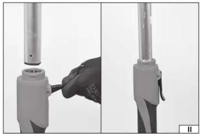
Handle extension arm installation (II)
The sander comes with a handle extension arm. The extension arm is mounted at the end of the handle.
Before assembly, pull the lever at the end of the handle. Insert the extension arm so that it is inside the handle and press the lever. Check that the extension arm does not move inside the handle.
There may be a mark on the extension arm which indicates the length to which it can be extended. Do not exceed the allowable extension arm length. If you do, this can cause the extension arm to slip out of the sander handle spontaneously, which can cause damage to the product and also lead to injury.
If there is no marker, at least 15 cm of the extension arm must be placed inside the handle.
To remove the extension arm, follow the above procedure in the reverse order.
Dust extraction hose installation (III)
The sander features a flexible hose with a bag to collect dust generated during operation.
Connect the hose to the end of the handle or to the end of the handle extension arm. When mounting to the extension arm, pull the lever at the end of the extension arm. Install so that the bayonet connector prevents the hose from disconnecting during operation and press down on the lever.
The sander has a fan which directs dust generated during operation to the bag.
The dust bag has a roll closure which allows the bag to be emptied. The bag filling level should be checked during operation and the bag itself emptied each time the dust extraction efficiency decreases. The bag should not be rolled further than the place marked with lines and arrows.
The bag can only be emptied when the sander is switched off. The power cord plug must be unplugged from the electric outlet.
The hose attached to the sander does not allow disassembly of the bag so as to connect the sander to an external dust extraction system. If necessary, the sander should be equipped with a separate hose.
Mounting the sandpaper sheet (IV)
Caution! Make sure the sandpaper sheet is free from damage before installing it. If you notice any damage in the form of folds, cracks, tears or holes, replace the sheet with a new one which is free of damage.
The sandpaper sheet must be provided with a surface which allows it to be attached on the disc by means of Velcro pad. The sheets should have holes in the same places as the holes in the tool disc. Only then will it be possible to extract the dust generated during operation effectively.
Place the sheet on the disc coaxially so that the holes in the sheet match the holes in the tool disc. The edge of the sandpaper disc must not come into contact with the tool guard or the peripheral brush of the guard.
PRODUCT OPERATION
Caution! All the assembly steps described above must be carried out before beginning operation.
EN
Battery installation (VI)
Warning! Before installing the battery in the tool, make sure that the power switch is in the off position, i.e. it is not pressed down. Slide the battery into the battery socket guides until it latches in the socket. A correctly installed battery cannot be removed otherwise than by pressing and holding the battery latch in this position, and then pulling the battery out of the tool socket.
Starting the sander
Do not start the sander while leaning the work head against any surface with the sanding sheet being in contact with any object.
This may lead to loss of control of the tool and cause serious injury.
The sander is fitted with a knob (V) which allows for the adjustment of the motor speed, which translates into disc rotation speed.
The knob is marked with appropriate signs to indicate the direction of the knob rotation for speed control.
Check that the product switch is in the "O" off position (VII).
Move the speed controller to the maximum speed position.
Start the dust extraction system.
Grip the sander with both hands - one hand on the front handle grip and the other on the rear handle grip.
Use your thumb to move the switch to the "I" on position (VIII).
The power switch is equipped with a lock that allows it to retain the "I" on position without the need for continuous hold. This makes extended work easier. Press the rear part of the power switch and allow it to retract to unlock the switch. If the power switch is not locked, releasing it will automatically move it to the "O" off position, which will stop the tool operation. The disc may be still spinning for some time after turning off the sander. Wait until the disc has stopped revolving completely before putting the sander down. It is forbidden to stop the disc by pressing it against the processed surface.
The disc will start operating at its nominal speed.
Hold the sander in this position and monitor its operation for approx. 1 minute. If you notice any signs of malfunction such as increased vibration or excessive noise, turn the sander off immediately using the power switch, remove the battery from the tool, and search for the cause of the malfunction. It is forbidden to resume operation without rectifying the fault.
If there are no signs of malfunction, you can adjust the speed and start working.
Grinder operation
Where required, the processed material must be secured, e.g. with vices or clamps, in such a manner that it cannot move during work. The sander disc rotates at a high speed and, if not properly secured, the material may move uncontrollably during work, which would increase the risk of serious injury.
Wear personal protective equipment, such as eye and hearing protection, a dust mask, safety gloves and appropriate work clothing. Make sure you carry out all assembly and adjustment steps.
Make sure that the power switch is in the "off" position, then connect the battery to the tool socket.
Always hold the sander with both hands gripping its front and rear handles. If the extension arm is used, grip the rear handle and the extension arm handle.
Allow the sander to reach full speed and only then start working the material.
After finishing work, use the power switch to turn off the sander, remove the battery from the tool, and proceed with maintenance.
Grinder operation tips
It is forbidden to hold the sander in any other way but by the handle grips. Do not hold the sander by any parts of the housing other than the handle grips.
Always hold the sander with both hands.
Do not press the sander against the processed surface too hard. Excessive pressure can cause the sander to overheat and damage the processed surface.
Position the sander so that the entire surface of the sanding sheet is used. This will ensure uniform wear of the sheet.
Move the sander towards and away from you, and gradually to a side. Do not move the sander in circles. Wood should be sanded along the grain. Sanding should be started with coarse-grit sandpaper, then use increasingly finer-grit sandpapers until the desired effect is achieved. Avoid checking the condition of the processed wood surface with your bare hand. This can cause injury from splinters and burrs generated during work.
The sander features two areas from which dust is transported to the dust extraction system. One area is the holes in the lower side of the work head, and the other one is a gap between the edge of the work head and the guard. The dust extraction force must be selected experimentally during operation. The greatest force will not always be the most effective. The airflow generated during operation may cause the sander to suck too much to the ground surface, which will make it difficult for dust to move towards the holes in the disc or its edges, and reduce the performance. If the extraction force is too low, the dust generated during operation will remain on the material.
The tool speed and sandpaper sheet grades must be selected according to the processed surface. Too high grit size of the sand-paper will produce scratches on the processed material surface.
Higher speeds should be used for sanding ceramic materials and non-resinous wood. Resin wood should be sanded at a lower speed. If the speed is too high, the resin in the wood will heat up quickly and the sanding sheet will become clogged. For a similar reason, sanding paints and varnishes should also be carried out at a lower speed.
EN
Take regular breaks during operation, checking the condition of the sanding sheet and the fill-up level of the dust extraction system. If a sanding sheet is found to have been clogged with dust generated during operation, or that the abrasive grain has worn, replace the sheet with a new one.
Battery storage
Ensure proper storage conditions to extend the battery's life. The battery can last for approximately 500 charge-discharge cycles. Store the battery at a temperature ranging from 0^ to 30^ at the relative air humidity of 50% . Charge the battery to approx. 70% of its total capacity to store it for a longer period of time. In case of prolonged storage, the battery should be periodically charged once a year. Do not over-discharge the battery as this will shorten its life and may cause irreparable damage.
During storage, the battery will gradually discharge due to leakage. The self-discharge process depends on the storage temperature – the higher the temperature is, the faster the discharge process is. If the batteries are stored incorrectly, the electrolyte may leak. In case of leakage, secure the leak with a neutralising agent. In the case of electrolyte contact with eyes, rinse eyes thoroughly with water, and immediately seek medical attention. It is not allowed to use the tool with a damaged battery. If the battery is completely worn, return it to a specialist waste disposal centre.
Transport of batteries
Lithium-ion batteries are treated as hazardous materials, according to legal regulations. The user of the tool can transport the product together with the battery and the batteries alone, by land. In that case, no additional conditions have to be met. If you entrust transport to third parties (e.g. a courier company), follow the regulations regarding the transport of hazardous goods. Before shipping, please contact a properly qualified person. It is not allowed to transport damaged batteries. For the duration of transport, remove the demountable batteries from the product and secure the exposed contacts, e.g. by covering them with insulation tape. Protect the batteries in the packaging in such a way that they do not move inside the packaging during transport. National regulations for the transport of hazardous materials must also be observed.
Charging the battery
Caution! Before charging, disconnect the power unit from the mains by removing the plug from the mains socket. In addition, remove any dirt and dust from the battery and battery clamps with a soft, dry cloth.
The battery has a built-in charge indicator. The LEDs will light up by pressing the button. The more of them come on, the more charged the battery is. If the LEDs do not light up when the button is pressed, the battery is discharged.
Disconnect the battery from the tool.
Slide the battery into the charger socket (X).
Plug the charger into a mains socket.
The red LED will light up, which indicates the charging process.
When charging is complete, the red LED will turn off and the green LED will light up to indicate that the battery is fully charged. Pull the power unit plug out of the mains socket.
Pull the battery out of the charging station by pressing the battery clamp button.
Caution! If the green LED lights up when the charger is connected to the mains, the battery is fully charged. In this case, the charger will not start the charging process.
PRODUCT MAINTENANCE
CAUTION! Disconnect the battery before carrying out any adjustment, servicing or maintenance work.
The disc head allows to remove the disc to clean the space between the disc and the drive guard thoroughly. Hold the disc with your hand, then use the wrench to loosen the disc retaining screw (IX). Clean the space between the disc, the disc itself and the guard of dust and other contaminants with a soft dry cloth, a jet of compressed air at a maximum pressure of 0.3 MPa, or a soft brush. Do not use sharp objects for cleaning.
Having finished working, check the device for damage by visually inspecting the exterior and the body and the handle, the functioning of the electric switch, the vents for clogging, the motor brushes for sparking, the noise level of the bearings and the drive transmission, and how the device starts and runs. During the warranty period, the user is not allowed to install any power tools or replace any components or parts, as this will void the warranty rights. Any irregularities found during the inspection or the operation signal the need for repair to be done at the service centre. After finishing work, the housing, ventilation openings, switches, auxiliary handle and covers should be cleaned e.g. with an air jet (with a pressure not exceeding 0.3 MPa), paintbrush or dry cloth without the use of chemicals and cleaning agents. Clean the tools and handles with a dry, clean cloth.
GERÄTEBESCHREIBUNG
CARACTÉRISTIQUES DU PRODUIT
Transport van accu's
DEKLARACJA ZGODNOŚCI DECLARATION OF CONFORMITY DECLARATIE DE CONFORMITATE
0422/YT-82360/EC/2022
We declare and guarantee with full responsibility that the following products:
meet requirements of the following European Standards / Technical Specifications:
and fulfil requirements of the following European Directives:
Serial number: concern all serials numbers of item(s) mentioned in this declaration
The person authorized to compile the technical file: