KD8072C - Fridge Atag - Free user manual and instructions
Find the device manual for free KD8072C Atag in PDF.

User questions about KD8072C Atag
0 question about this device. Answer the ones you know or ask your own.
Ask a new question about this device
Download the instructions for your Fridge in PDF format for free! Find your manual KD8072C - Atag and take your electronic device back in hand. On this page are published all the documents necessary for the use of your device. KD8072C by Atag.
USER MANUAL KD8072C Atag
Installation instructions
Refrigerators and freezers for integrated use, door-on-door
1 General safety information. 14
2 Installing the appliance. 14
3 Changing over door hinges. 14
3.1 Demount door 15
3.2 Change freezer compartment door.. 15
3.3 Changing bearing parts.. 15
3.4 Re-fit door. 15
4 Installation
4.1 Installing the appliance 17
4.2 Fitting the unit door 18
5 Connecting the appliance. 19
The manufacturer works constantly on the further development of all the types and models. Therefore please understand that we have to reserve the right to make design, equipment and technical modifications.
To get to know all the benefits of your new appliance, please read the information contained in these instructions carefully.
The instructions apply to several models. Differences may occur. Text relating only to specific appliances is marked with an asterisk (^*)
Instructions for action are marked with a the results of action are marked with a
1 General safety information
|  | DANGER identiFies a situation involving direct danger which, if not obviated, may result in death or severe bodily injury. |
|  | WARNING idenfies a dangerous situation which, if not obviated, may result in death or severe bodily injury. |
|  | CAUTION idenfies a dangerous situation which, if not obviated, may result in minor or medium bodily injury. |
| NOTICE identifies a dangerous situation which, if not obviated, may result in damage to property. | |
| Note identifies useful information and tips. |
It is important that the procedures and directions given in these instructions are complied with in order that the appliance is correctly installed and works properly. Read and grasp all the information in these instructions before the appliance is installed.
2 Installing the appliance
In the event that the appliance is damaged, contact the supplier immediately before connecting to the mains.
The floor at the site must be flat and level.
Do not install the appliance in a location where it is exposed to direct radiation of the sun, next to a cooker, heater and similar. Do not install the appliance without assistance.
Standard EN 378 specifies that the room in which you install your appliance must have a volume of 1m^2 per 8g of R 600a refrigerant used in the appliance. If the room in which the appliance is installed is too small, a flammable gas-air mixture may form in the event of a leakage in the refrigeration circuit. The quantity of refrigerant used in your appliance is indicated on the type plate on the inside of the appliance.
Fit the appliance in stable kitchen units only.
The following ventilation gaps must be observed:
The depth of the ventilation channel at the rear of the unit must be at least 38mm
There must be a ventilation space of at least 200cm^2 in the plinth and at the top of the unit.
- Basically the principle applies: the larger the ventilation space, the more energy-saving the appliance is in operation.

Fire hazard due to dampness!
If live parts or the mains lead become damp this may cause short circuits.
The appliance is designed for use in enclosed areas. Do not operate the appliance outdoors or in areas where it is exposed to splash water or damp conditions.

WARNING
Fire hazard due to refrigerant!
The refrigerant R 600a is environmentally friendly but flammable. Escaping refrigerant may ignite.
Do not damage the piping of the refrigeration circuit.

WARNING
Fire hazard and danger of damage!
Do not place appliances emitting heat e.g. microwaves, toasters etc. on the appliance!
- Detach the connecting cable from the rear of the appliance, removing the cable holder at the same time because otherwise there will be vibratory noise!
After installation:
Remove the protective film from the decorative trims.*
Remove the protective film from the decorative trims and drawer fronts.*
Remove all transit supports.
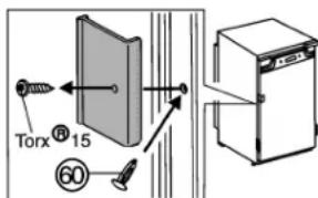
Unscrew the red transport lock. Close the vacated retaining hole using the stopper (60).
Dispose of packaging material.
Note
Clean the appliance.
If the appliance is installed in a very damp environment, condensate may form on the outside of the appliance.
Always see to good ventilation at the installation site.
3 Changing over door hinges
Ensure that the following tools are to hand:
Cordless screwdriver Torx® 15
Cordless screwdriver Torx® 20
Cordless screwdriver Torx® 25
Slide the appliance 2/3 of the way into the recess.
Pull out the power plug.
Open the door.
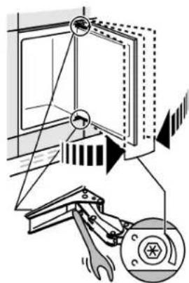
3.1 Demount door
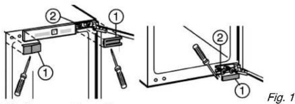
Lift off covers Fig. 1 (1).
Only slacken fastening screws Fig. 1 (2).
Remove door: push outwards, unhinge and set aside.
3.2 Change freezer compartment door*
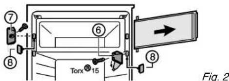
Fold away cover of turn hinge Fig. 2 (6).
Unscrew turn hinge Fig. 2 (6) together with compartment door.
Unscrew closing element Fig. 2 (7).
- Close the vacated holes with the accompanying stoppers Fig.2 (8).
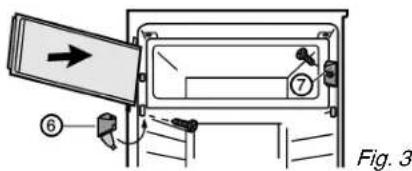
Fit closing element Fig. 3 (7).
Fit compartment door at the top.
Fit turn hinge Fig. 3 (6) and fold the cover.
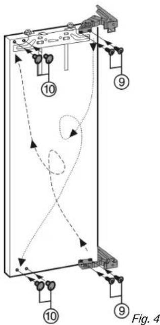
3.3 Changing bearing parts

CAUTION
Risk of injury if hinges fold!
Leave hinges open.
Transfer top and bottom fastening screws Fig.1 (2) to the opposite side.
Screws are self-tapping. Use cordless screwdriver:
Unscrew Fig. 4 (9) the hinges from the door, transfer them and screw them on tightly (4 Nm).
- Close vacated fastening holes with stoppers Fig. 4 (10).
3.4 Re-fit door
Attach appliance door to the prefitted fastening screws Fig.1 (2).
Screw in mounting screws Fig. 1 (2) tightly (4 Nm).
Re-fit covers Fig. 1 (1).

WARNING
Risk of injury due to the door dropping out!
If the fastening parts are not screwed into place firmly enough, the door may drop out. This may lead to severe injuries. What is more, the door may not close and therefore the appliance may fail to cool properly.
Screw the hinges firmly into place (with 4Nm
Check all of the screws and retighten if necessary.
4 Installation
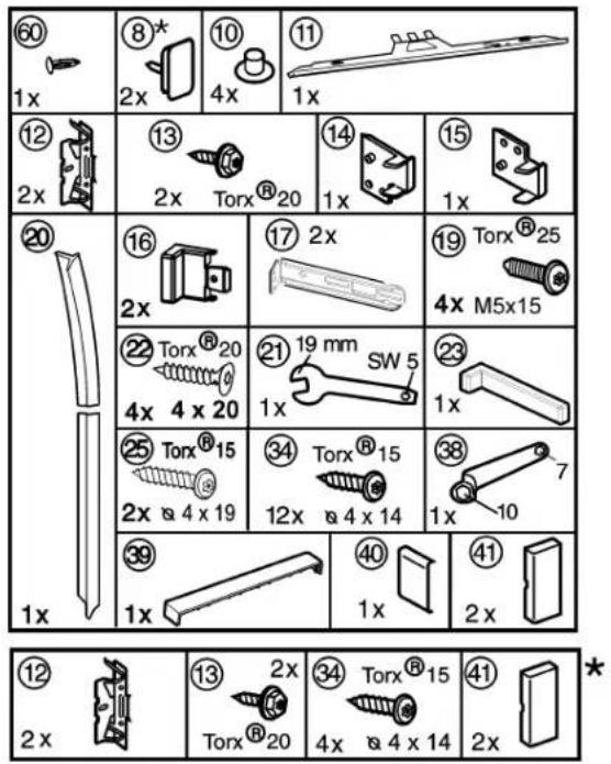
All the mounting components accompany the appliance.
Make sure the following tools are on hand:
Cordless screwdriver Torx 15,20,25
Allen key 13
Screwdriver
The intermediate base and side wall of the kitchen unit have to be at right angles to one another. Align the kitchen unit using a spirit level and angle. If necessary, use shims.
The appliance can also be installed in an ordinary kitchen cabinet. In this case detach the fittings of the unit door and recess. They are no longer needed as the unit door is fitted to the appliance door.
Check installation dimensions:
| a | b |
| 712 mm 714 mm - 730 mm | |
| 872 mm 874 mm - 890 mm | |
| 1022 mm 1024 mm - 1040 mm | |
| 1218 mm 1220 mm - 1236 mm | |
| 1395 mm 1397 mm - 1413 mm | |
| 1770 mm 1772 mm - 1788 mm |
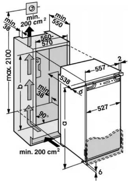
Fig. 6
Note
Before assembling the door of the unit, make sure that the admissible weight of the unit door is not exceeded.
- Otherwise damage to the hinges and resultant malfunction cannot be ruled out.
| Model Max. weight of unit | door |
| KD8102ADUU, KD8102BDUU 13 kg | |
| KD8088ADUU 16 kg | |
| KD8140ADUU, KD8140BDUU 18 kg | |
| KD8122BFUU, KD8122AFUU 19 kg | |
| KD8140CDUU, KD8072CUU, KD8140AFUU | 20 kg |
| KD8178AFUU, KD8178CDUU 23 kg |
4.1 Installing the appliance

Fig. 7
- Detach the connecting cable from the rear of the appliance. Remove the cable holder otherwise there will be vibratory noise.
Lay the connecting cable with the help of string in such a way that the appliance can be easily connected following installation.

▶ Slide the appliance 3/4 of the way into the recess.
Remove the covers Fig. 7(4,6,7).
Fit the equaliser trim Fig.9(11) concentrically onto the appliance: Slide it into the recess and engage it in the keyholes.
Screw all the mounting brackets Fig. 10 (12) to the pre-drilled holes in the appliance door using hexagon screws Fig. 10 (13).
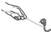
Fig. 8
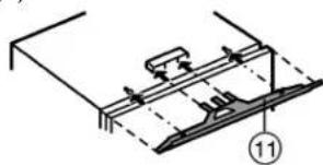
Fig. 9
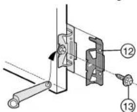
Fig. 10
For 16 mm-thick unit walls:
Clip spacer Fig. 11 (14) and spacer Fig. 7 (15) onto the hinges.
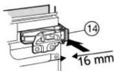
Fig. 11
Attach the top cover Fig. 12 (16) and the bottom cover Fig. 12 (17) to the mounting brackets.
- Fasten the top mounting bracket Fig. 12 (17) with screws Fig. 12 (19) and the bottom one with screws Fig. 7 (19) so that the brackets can still be moved a little to the left and right.
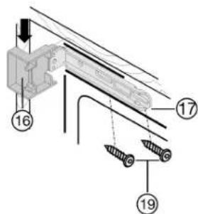
Fig. 12
- Strip the protective film off the cover trim Fig. 13 (20).
Apply the cover trim Fig. 13 (20) to the projection of the cover Fig. 12 (16) on the handle side, flush with the front, and adhesively affix it to the side wall of the appliance.
If necessary, shorten the cover strip Fig. 13 (20) at the bottom: The cover strip Fig. 13 (20) has to end 3mm above the upper edge of the lower mounting bracket Fig.7(17).
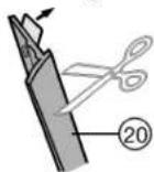
Fig. 13
Slide in and align the appliance:
▶ Slide in the appliance until the covers Fig. 12 (16)abut Fig. 12 against the side wall of the kitchen unit.
For 16 mm-thick unit walls:
- Allow the spacers to abut against the side wall of the kitchen unit.
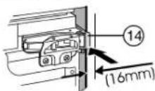
Fig. 14
For 19 mm-thick unit walls: Align the front edges of the hinges so as to be flush with the side wall of the kitchen unit.
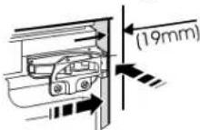
Fig. 15
For kitchen units (16 mm and 19 mm) with door stop components (knobs, sealing lips etc.):
- Allow for the extra distance (depth of the door stop components): Allow hinges and covers Fig. 12 (16) to protrude by the extra distance.
All appliances:
Vertically align the appliance by means of the height-adjustable feet, using the accompanying open-ended spanner Fig. 7 (21).
The appliance is now correctly positioned in depth. The distance from the front edge of the side wall of the unit to the appliance body is 42mm all the way round (allow for door stop components, such as knobs and sealing lips.)
Note
Incorrect installation will lead to malfunction! If the distance is not kept, the door may not close. This may lead to icing, to condensate forming and to malfunction.
Be sure to keep to the clearance of 42mm all the way round. (Allow for door stop components, such as knobs and sealing lips.)
Tightly screw the appliance into place in the recess:
By screwing long Spax screws Fig.16 (22) through the top and bottom hinge plates.
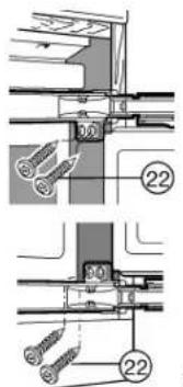
Fig. 16
On the handle side at the top:
Loosen the screws Fig.17(19) a little.
Tightly screw the top mounting bracket Fig.17 (17) to the unit wall using Spax screw Fig.1725 品 4 × 1 9
Break off the projecting end of the cover Fig.17(16).
Tighten the screws Fig. 17(19).
Put on the cover Fig. 17 (16).
On the handle side at the bottom:
Loosen the screws Fig.18 (19) a little.
Tightly screw the bottom mounting bracket Fig.18 (17) to the unit wall using Spax screw Fig.182504x19.
Break off the projecting end of the cover Fig.18(16).It is no longer required.
▶ Tighten the screws Fig. 18 (19).
Put the cover Fig. 18 (23) on the bottom mounting bracket Fig. 18 (17).
Close the appliance door.

Fig. 17
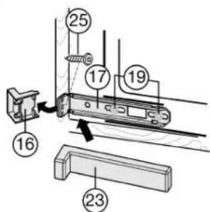
Fig. 18
4.2 Fitting the unit door
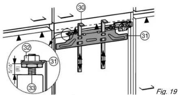
Check 8 mm-presetting. (Distance between appliance door and lower edge of crosspiece)
▶ Slide up the assembly aids Fig. 19 (30) to the height of the unit door. Lower stop edge of the assembly aid = upper edge of the unit door to be fitted.
Unscrew the crosspiece Fig. 19 (31) by undoing the locknuts Fig. 19 (32).
Attach the crosspiece Fig. 20 (31) together with the assembly aids Fig. 20 (30) to the inside of the unit door.
Concentrically align the crosspiece Fig.20 (31):Mark a short centre line on the unit door and put the tip of the arrow on the crosspiece over it.
Distances to the outer edge are equal at the left and right. For particle board doors:
Tightly screw the crosspiece Fig. 20 (31) into place using at least 6 screws Fig. 20 (34).
For frame and panel doors:
Tightly screw the crosspiece Fig. 20 (31) into place using 4 screws Fig. 20 (34) at the edge.
- Raise and remove the assembly aids Fig. 20 (30), turn them and slide them into the adjacent openings.
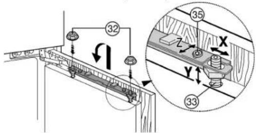
Fig. 21
Attach the unit door to the adjusting bolts Fig. 21 (33) and loosely screw the locknuts Fig. 21 (32) onto the adjusting bolts.
Close the door.
Check the gap between the door and the surrounding unit doors.
To laterally align the unit door: Move the unit door in the X direction.
To align the unit door in height Y and in lateral inclination: Adjust the adjusting bolts Fig. 21 (33) using a screwdriver.
The unit door is flush and in alignment with the surrounding unit fronts.
Tighten the lock nuts Fig. 21 (32).
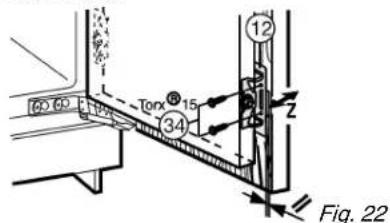
Ensure that both metal edges are flush (symbol /):
Drill pilot holes in the door of the unit (possibly make preliminary hole with a bradawl).
Screw the appliance door to the unit door with screws Fig.22 (34) passed through the mounting brackets Fig.22 (12).
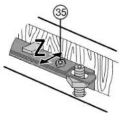
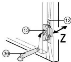
Fig. 23
To align the unit door in depth: Undo top screws Fig.23 (35), bottom hexagon screws Fig. 23 (13), then move the door.
Do not allow the knobs and sealing lips to abut - vital for proper function!
- Allow an air gap of 2mm between the unit door and the body of the unit.
For large or sectioned unit doors:
fit a 2nd pair of mounting brackets Fig.10 (12).
Use the holes pre-drilled in the handle area of the appliance door for this purpose.
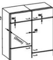
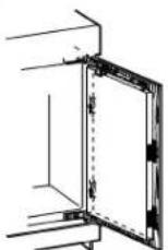
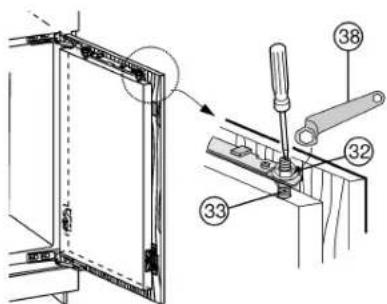
Fig. 24
Check the fit of the door and adjust if necessary.
Tighten all screws.
- Tighten the locknuts Fig. 24 (32) using the ring spanner Fig. 24 (38), while holding fast the adjusting bolts Fig. 24 (33) with a screwdriver.
Attach top cover Fig.25 (39) and snap into place.
Attach side cover Fig.25 (40) push it to the limit and then press until it audibly snaps into place.
Attach covers Fig. 25 (41) sideways, then draw them forwards with a screwdriver so that they snap into place well.
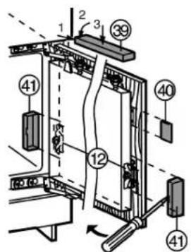
Fig. 25
Put on and engage the covers Fig. 7 (4,6,7).
Door stop cushioning can be adjusted in appliances with an aperture height of up to 1220mm
The door stop cushioning can be adjusted if necessary using the accompanying Allen key 5:
For stronger spring force: turn clockwise.
For lesser spring force (as-delivered): turn anticlockwise.
GB
Check the following points to ensure the appliance is fitted properly. Failure to do so may lead to icing, condensate forming and malfunction:
The door has to close properly
The unit door must not butt against the unit body
The seal must have a firm fit at the upper corner on the handle side. To check, darken the room, place a torch inside the appliance at the top and close the door. If light shines through, check the assembly.
5 Connecting the appliance
NOTICE
Risk of damage to the electronic control system!
Do not use stand-alone inverters (conversion of d.c. to a.c./ three-phase) or energy saving plugs.

WARNING
Fire and overheating hazard!
Do not use extension cables or multiple socket outlets.
The type of current (alternating current) and voltage at the installation site have to conform with the data on the type plate (see Appliance at a glance).
Connect the appliance only with a properly installed socket outlet with earthing contact. The socket outlet must be fused with 10 A or higher.

It must be easily accessible so that the appliance can be quickly disconnected from the supply in an emergency. It must be outside the area of the rear of the appliance.
Check the electrical connection.
Plug in the power plug.