
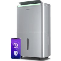
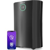
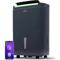
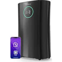
CircleDry Smart - Dehumidifier Klarstein - Free user manual and instructions
Find the device manual for free CircleDry Smart Klarstein in PDF.

| Product type | Air dehumidifier |
| Brand | Klarstein |
| Model | CircleDry Smart |
| Article numbers | 10045542, 10045543 |
| Power supply | 220-240 V ~ 50 Hz |
| Input power | 260 W (10045542), 290 W (10045543) |
| Dimensions (L x D x H) | 256 x 205 x 400 mm |
| Water tank capacity | 2 liters |
| Dehumidification (30 °C, RH 80%) | 12 L/day (10045542), 16 L/day (10045543) |
| Refrigerant | R290 (38-40 g, flammable) |
| Operating temperature range | 5 °C - 32 °C |
| Control | Touch panel + smartphone app via 2.4 GHz WiFi |
| Functions | Timer (1-24 h), humidity setting (30-90% + continuous and comfort mode), automatic defrost, automatic shut-off when tank full |
| Maintenance | Clean filter every 2 weeks with cold water |
| Safety | Refrigerant leak protection, automatic shut-off, defrost, use by children from 8 years |
| Drainage | Removable tank or continuous drainage via hose (not included) |
| Included accessories | User manual |
Frequently Asked Questions - CircleDry Smart Klarstein
User questions about CircleDry Smart Klarstein
0 question about this device. Answer the ones you know or ask your own.
Ask a new question about this device
Download the instructions for your Dehumidifier in PDF format for free! Find your manual CircleDry Smart - Klarstein and take your electronic device back in hand. On this page are published all the documents necessary for the use of your device. CircleDry Smart by Klarstein.
USER MANUAL CircleDry Smart Klarstein
bar
| Category | Value | |---|---| | Category 1 | 100 | | Category 2 | 100 | | Category 3 | 100 | | Category 4 | 100 | | Category 5 | 100 | | Category 6 | 100 | | Category 7 | 100 | | Category 8 | 100 | | Category 9 | 100 | | Category 10 | 100 | | Category 11 | 100 | | Category 12 | 100 | | Category 13 | 100 | | Category 14 | 100 | | Category 15 | 100 | | Category 16 | 100 | | Category 17 | 100 | | Category 18 | 100 | | Category 19 | 100 | | Category 20 | 100 | | Category 21 | 100 | | Category 22 | 100 | | Category 23 | 100 | | Category 24 | 100 | | Category 25 | 100 | | Category 26 | 100 | | Category 27 | 100 | | Category 28 | 100 | | Category 29 | 100 | | Category 30 | 100 | | Category 31 | 100 | | Category 32 | 100 | | Category 33 | 100 | | Category 34 | 100 | | Category 35 | 100 | | Category 36 | 100 | | Category 37 | 100 | | Category 38 | 100 | | Category 39 | 100 | | Category 40 | 100 | | Category 41 | 100 | | Category 42 | 100 | | Category 43 | 100 | | Category 44 | 100 | | Category 45 | 100 | | Category 46 | 100 | | Category 47 | 100 | | Category 48 | 100 | | Category 49 | 100 | | Category 50 | 100 | | Category 51 | 100 | | Category 52 | 100 | | Category 53 | 100 | | Category 54 | 100 | | Category 55 | 100 | | Category 56 | 100 | | Category 57 | 100 | | Category 58 | 100 | | Category 59 | 100 | | Category 60 | 100 | | Category 61 | 100 | | Category 62 | 100 | | Category 63 | 100 | | Category 64 | 100 | | Category 65 | 100 | | Category 66 | 100 | | Category 67 | 100 | | Category 68 | 100 | | Category 69 | 100 | | Category 70 | 100 | | Category 71 | 100 | | Category 72 | 100 | | Category 73 | 100 | | Category 74 | 100 | | Category 75 | 100 | | Category 76 | 100 | | Category 77 | 100 | | Category 78 | 100 | | Category 79 | 100 | | Category 80 | 100 | | Category 81 | 100 | | Category 82 | 100 | | Category 83 | 100 | | Category 84 | 100 | | Category 85 | 100 | | Category 86 | 100 | | Category 87 | 100 | | Category 88 | 100 | | Category 89 | 100 | | Category 90 | 100 | | Category 91 | 100 | | Category 92 | 100 | | Category 93 | 100 | | Category 94 | 100 | | Category 95 | 100 | | Category 96 | 100 | | Category 97 | 100 | | Category 98 | 100 | | Category 99 | 100 | | Total (Total) = [sum of bars] / [values] * (sum of bars + bars) * (sum of bars + bars) * (sum of bars + bars) * (sum of bars + bars) * (sum of bars + bars) * (sum of bars + bars) * (sum of bars + bars) * (sum of bars + bars) * (sum of bars + bars) * (sum of bars + bars) * (sum of bars + bars) * (sum of bars + bars) * (sum of bars + bars) * (sum in brackets) * (sum in brackets) * (sum in brackets) * (sum in brackets) * (sum in brackets) * (sum in brackets) * (sum in brackets) * (sum in brackets) * (sum in brackets) * (sum in brackets) * (sum in brackets) * (sum in brackets) * (sum in brackets) * (sum in brackets) * (sum in brackets) * (sum in brackets) * (sum in brackets) * (total).* (sum in brackets) * (sum in brackets) * (sum in brackets) * (sum in brackets) * (sum in brackets) * (sum in brackets) * (sum in brackets) * (sum in brackets) * (sum in brackets) * (sum in brackets) * (sum in brackets) * (sum in brackets) * (total).* (sum in brackets) * (sum in brackets) * (sum in brackets) * (sum in brackets)INHALT
Technische Daten 3
Warnungen 4
BEDIENUNG
Bedienfeld
1. POWER
natural_image
Diagram of a device with a black arrow pointing to a component, showing no text or symbols.natural_image
Line drawing of a portable air conditioner unit connected to a battery (no text or symbols)Filter-Entfernung
natural_image
Symbol of a trash bin crossed with a diagonal line, no text or numbers presentBerlin Brands Group UK Limited
PO Box 42
272 Kensington High Street
London, W8 6ND
United Kingdom
Congratulations on purchasing this equipment. Please read this manual carefully and take care of the following hints on installation and use to avoid technical damages. Any failure caused by ignoring the items and cautions mentioned in the operation and installation instructions are not covered by our warranty and any liability. Scan the QR code to get access to the latest user manual and more product information.

CONTENTS
Technical Data 23
Warnings 24
Safety Instructions 25
Transport, marking and storage 26
Product Overview 27
Operation 28
Device Control by Smartphone 30
Draining Instruction 32
Maintenance 33
Decommissioning 37
Disposal Considerations 40
Declaration of Conformity 40
TECHNICAL DATA
| Article number 10045542 10045543 | ||
| Power supply 220-240 V~ / 50 Hz | ||
| Power input 260 W 290 W | ||
| Moisture removal (30 °C, RH80%) 12 litres/day 16 litres/ day | ||
| Refrigerant (amount) R290 (38 g) R290 (40 g) | ||
| Permissible excessive operating pressure | Suction: 0.6 MPaDischarge: 2.5 MPa | |
| Maximum allowable pressure 4.0 MPa | ||
| Dimension (W x D x H) mm 256x205x400 | ||
| Applicable temperature 5 °C-32 °C | ||
| Water tank capacity 2 litres | ||
WARNINGS
WARNING: This appliance uses the flammable refrigerant R290. The appliance with R290 refrigerant may cause serious damage to the human body or surrounding objects if handled roughly.
The space required for the installation, use, repair and storage of this appliance must be in accordance with the following table:
- Do not use any methods to speed up defrosting or to clean frozen parts, except as specifically recommended by the manufacturer.
- Do not puncture or burn the appliance and check the refrigerant line for damage.
• The appliance should be stored in a room without a permanent source of fire, such as an open flame, a burning gas appliance, a working electric heater, etc.
• Note that refrigerants can be odourless. - The appliance should be stored in a way that prevents mechanical damage caused by accidents.
- Maintenance or repair of appliances using R290 refrigerant must be carried out after a safety check to minimise the risk of incidents.
- Please read the instructions carefully before installation, use and maintenance.
| Symbol Explanation | |
 | This symbol indicates that this appliance uses a flammable refrigerant. If the refrigerant leaks and is exposed to an external ignition source, there is a risk of fire. |
 | This symbol indicates that this manual should be read carefully. |
 | This symbol indicates that the equipment should be handled by service personnel with reference to the installation manual. |
 | This symbol shows that information is available such as the operating manual or installation manual. |
SAFETY INSTRUCTIONS
- Do not use means to accelerate the defrosting process or to clean, other than those recommended by the manufacturer.
- The appliance shall be stored in a room without continuously operating ignition sources (for example: open flames, an operating gas appliance or an operating electric heater.)
- Do not pierce or burn.
- Be aware that refrigerants may not contain an odour.
- The appliance shall be installed, operated and stored in a room with a floor area larger than 4m^2 .
- Servicing shall be performed only as recommended by the manufacturer.
- The appliance shall be stored in a well-ventilated area where the room size corresponds to the room area as specified for operation.
- All working procedure that affects safety means shall only be carried by competent persons.
- Please read the manual carefully before the first time using this product, and storage the unit in safe place to avoid electricity leakage, flaming or person injure.
- Do not put this product in the water or any other liquids.
- If the supply cord is damaged, it must be replaced by the manufacturer, its service agent or similarly qualified persons in order to avoid a hazard.
- Please ask professional service agent to repair the product. Improper repair might cause damage to users.
- Disconnect the appliance from power supply before moving or cleaning the product, and also when the product is not in used.
- Please operate the product with specified electricity voltage.
- Please use this product only for household appliance and follow the designed purpose.
- Do not put any stuff on the product.
- In order to avoid water leakage, please clean the water tank before moving the product.
- Do not incline the product, or leaking water may damage the product.
- This appliance can be used by children aged from 8 years and above and persons with reduced physical, sensory or mental capabilities or lack of experience and knowledge if they have been given supervision or instruction concerning use of the appliance in a safe way and understand the hazards involved. Children shall not play with the appliance. Cleaning and user maintenance shall not be made by children without supervision.
- Please keep the product from the wall or other barriers in a minimum distance of 50 cm.
- The appliance shall be installed in accordance with national wiring regulations.
- The applicable operating temperature range for this unit is 5-32 °C.
- Do not operate your dehumidifier in a wet room such as a bathroom or laundry room.
- Spaces where refrigerant pipes shall be compliance with national gas regulations.
TRANSPORT, MARKING AND STORAGE
Transportation
- The transportation of equipment containing flammable refrigerants must comply with transport regulations.
Marking and disposal
- The marking of equipment with signs must comply with local regulations.
- Disposal of equipment containing flammable refrigerants must comply with national regulations.
Storage
- Equipment should be stored in accordance with the manufacturer's instructions.
- The protection of the storage package should be such that mechanical damage to the equipment inside the package will not cause a leakage of the refrigerant charge. The maximum number of units that can be stored together is determined by local regulations.
- The unit must be stored in such a way that mechanical damage cannot occur.
General working area
- All maintenance personnel and others working in the local area must be instructed as to the nature of the work.
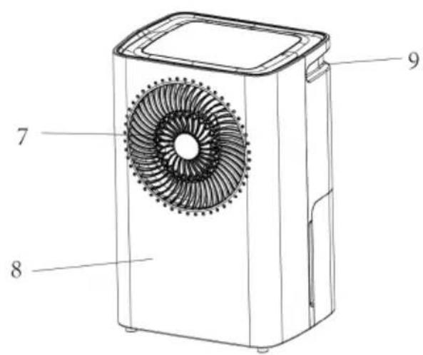
PRODUCT OVERVIEW
- Control panel
- Air inlet
- Drain hole
- Water tank
- Handle
- Back housing
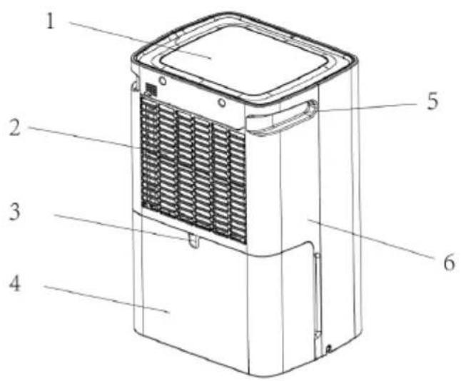
- Air outlet
- Front housing
- Handle
OPERATION
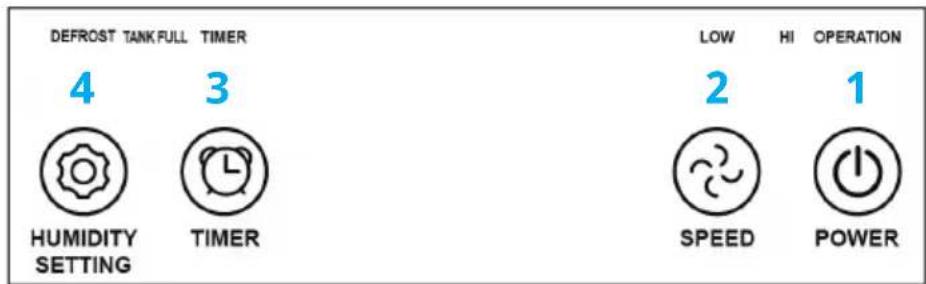
Control panel

1. POWER
Press this key to turn "on" or "off" corresponding indicating light on or off (While the indoor humidity reaches the setting value, the compressor will stop running and the indicating light will flash.)
2. FAN SPEED
Press the key to choose high speed (HI) or low speed (LOW), and the relating indicating light may follow the instruction to illuminate or extinguish.
3. TIMER
a. Press the key to set time you need. (1 to 24 hours)
b. When setting timer in stand-by mode, the unit will be turned on automatically; when setting timer in operating mode, the unit will be turned off automatically.
c. If pressing the power key to turn off the unit before time finishes counting down, the setting timer will be canceled.
d. While the timer is in used, the indicating light illuminates.
e. After set the timer, the display may switch back to show the ambient humidity.
4. Humidity setting
Press the key to set the relative humidity you need. (From continuous dehumidification [CO] to relative humidity 30%, 35%, 40%. 45%, ....., 90%, comfort mode [AU], and back to continuous dehumidification [CO]. The first time you electrify the unit, the unit is set to be continuous dehumidification [CO].
When ambient humidity is lower than setting humidity by 3%, compressor will stop automatically, and return working until the ambient humidity is higher than setting humidity by 3%.
Wi-Fi indicator
Press and hold the "HUMIDITY SETTING" button for 3 seconds to enter the Wi-Fi setup mode; if the Wi-Fi indicator lights up, it means that the device is successfully connected to the Wi-Fi; if the Wi-Fi indicator flashes, it means that the device is in Wi-Fi setup mode.
Comfort mode
- When the ambient temperature is lower than 5^ C, the compressor will stop working.
- When the ambient temperature is higher than 5 °C and lower than 20 °C, the product will set the humidity to 60% automatically.
- When ambient temperature is higher than 20 °C and lower than 27 °C, the product will set the humidity to 55% automatically.
- When ambient temperature is higher than 27 °C , the product will set the humidity to 50% automatically.
Water full indicator: When the water tank is full, the indicating light will illuminate and the unit will stop working until empty the water tank.
Defrost: When the unit is defrosting, the indicating light will illuminate and the compressor will stop working but the motor will keep operating.
Notes
- When operating the dehumidifier, please do not set the humidity higher than the ambient humidity.
- When indicating light illuminates, please pour the water out of the tank and put it back. Then the product will resume working.
- When the product shut down, please wait at least 3 minutes before restarting the unit to prevent damaging the compressor.
- The applicable operating temperature range for this unit is 5-32 °C.
- If the dehumidifier can't start (the indicating light does not illuminate) or the dehumidifier shut down unreasonably, please make sure whether the plug is connected firmly to power supply. If the plug and power supply are in normal condition, please wait for 10 minutes before restart the unit (because it takes 10 minutes to reposition). If the unit still does not start after 10 minutes, please ask your local distributor service station to repair.
- When the dehumidifier is operating, it's a normal situation that the working compressor may cause some heat and bring the ambient temperature up.
- When the product is defrosting, the related indicating light will illuminate. The compressor stops while defrosting but the motor keeps running.
- The unit shows the ambient humidity when it's operating. If the ambient humidity is higher than RH95%, the display shows "HI"; if the ambient humidity is lower than RH35%, the display shows "LO"
- Please face to the front of the unit to move the machine.
DEVICE CONTROL BY SMARTPHONE
If you integrate the device into your home WiFi, you can conveniently operate it via the associated Klarstein app. The app not only allows you to remotely control the device via your smartphone, but also gives you access to recipes and additional information.
Follow these steps to connect your smartphone to your Klarstein device:
1 Download the Klarstein app first by scanning the QR code with your smartphone (see below), or download it directly from App Store or Google Play.
2 Make sure your smartphone is connected to the same WiFi network that your Klarstein device is to be connected to.
3 Open the Klarstein app.
4 Sign in to your account. If you do not have an account, sign up in the Klarstein app.
5 Follow the instructions from the app.
App Download
Use the scan function of your smartphone to scan the QR code and save the app on your smartphone.
Note: The app provides further information on how to use the app and help on how to connect to your device as soon as you open it for the first time.
| iOS Android | |
 |  |
Troubleshooting connection problems
If your Klarstein device cannot be found in the WLAN, check the following:
1 The device is not plugged in. Make sure that your device is plugged into an electric socket.
2 The device is not in pairing mode. Make sure that the WiFi indicator (LED) on the smart device control panel is blinking as described in the 'Reset WiFi settings' instruction of your smart device (instructions are usually available on device connection process).
3 The WiFi access point does not operate on 2.4 GHz. Make sure that your access point operates on 2.4 GHz band and you have a separate SSID on 2.4 GHz band. If you are not sure about the operating band of your access point, please contact your internet provider company.
Important: please note that if your WiFi router is dual band - operating on both 2.4 GHz and 5 GHz band - you need to separate the SSIDs for each band and use the 2.4 GHz SSID for connection.
4 Firewall settings of your WiFi network; the firewall setting of your WiFi network may not allow the Klarstein app to configure the WiFi settings on your smart device. Please make sure that you are not using a public WiFi network, e.g. airports, dormitories, companies, etc.
5 Different credentials used in smartphone and the app. Make sure that the WiFi credentials entered in the Klarstein app are the same as the ones that your smartphone is connected to.
Following the above mentioned points, if your smart device still fails to connect to the app, please contact us via email for support: appsupport@go-bbg.com
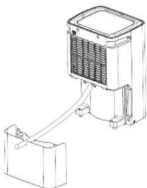
DRAINING INSTRUCTION
Drained water can be stored in the water tank or continuously drained by means of a PVC pipe. (The PVC pipe is not supplied with the product).
Usage of water tank
When dehumidifying, the condensing water may be drained to water tank. The unit stops working and illuminates the indicating when the water tank is full of water.
Please pour out the water that time.
- Take out the water tank (see illustration.) and pour out the water.
- Put the water tank back.
- Press power key to turn on the unit.

natural_image
Diagram of a mechanical device with a housing and internal components, showing an arrow pointing to a component (no text or symbols present)Continuous drainage
- Before continuous draining water, please take out the water tank and plug a draining tube to draining hole (See Fig 02.) Then put the water tank back.
- Draining tube should place lower than the draining hole to let water flow out.
natural_image
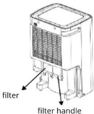
Line drawing of a portable air conditioner unit connected to a battery (no text or symbols)Filter removal
- Take out the water tank before remove the filter.
- Pulling out the filter with handles of filter.
- Wash the filter with cool water (cooler than 40 °C) every two weeks, and put filter back after it air-dried naturally.
4.
MAINTENANCE
- Do not place the unit on a soft or uneven surface to avoid noise, vibration, water or electrical leakage during operation.
- Never insert thin rods or hard objects into the unit to avoid damage.
- Unplug the power cord from the wall outlet when you turn the unit off or when it is not going to be used for an extended period of time.
- To improve the performance of the dehumidifier, store it in an open area away from any obstructions that may block the air.
- Please wash the filter with cool water (cooler than 40^ ) but not gasoline or alcohol every two weeks, and put filter back after it air-dried naturally.
Information on servicing

WARNING Risk of electric shock or other personal injury!
Do not repair the appliance yourself. The device may only be repaired by qualified personnel. The repair must be carried out professionally.
1) Checks to the area
Prior to beginning work on systems containing flammable refrigerants, safety checks are necessary to ensure that the risk of ignition is minimised. For repair to the refrigerating system, the following precautions shall be complied with prior to conducting work on the system.
2) Work procedure
Work shall be undertaken under a controlled procedure so as to minimise the risk of a flammable gas or vapour being present while the work is being performed.
3) Checking for presence of refrigerant
The area shall be checked with an appropriate refrigerant detector prior to and during work, to ensure the technician is aware of potentially flammable atmospheres. Ensure that the leak detection equipment being used is suitable for use with flammable refrigerants, i.e. non-sparking, adequately sealed or intrinsically safe.
4) Presence of fire extinguisher
If any hot work is to be conducted on the refrigeration equipment or any associated parts, appropriate fire extinguishing equipment shall be available to hand. Have a dry powder or CO2 fire extinguisher adjacent to the charging area.
5) No ignition sources
No person carrying out work in relation to a refrigeration system which involves exposing any pipe work that contains or has contained flammable refrigerant shall use any sources of ignition in such a manner that it may lead to the risk of fire or explosion. All possible ignition sources, including cigarette smoking, should be kept sufficiently far away from the site of installation, repairing, removing and disposal, during which flammable refrigerant can possibly be released to the surrounding space. Prior to work taking place, the area around the equipment is to be surveyed to make sure that there are no flammable hazards or ignition risks. "No Smoking" signs shall be displayed.
6) Ventilated area
Ensure that the area is in the open or that it is adequately ventilated before breaking into the system or conducting any hot work. A degree of ventilation shall continue during the period that the work is carried out. The ventilation should safely disperse any released refrigerant and preferably expel it externally into the atmosphere.
7) Checks to the refrigeration equipment
Where electrical components are being changed, they shall be fit for the purpose and to the correct specification. At all times the manufacturer's maintenance and service guidelines shall be followed. If in doubt consult the manufacturer's technical department for assistance.
The following checks shall be applied to installations using flammable refrigerants:
- The charge size is in accordance with the room size within which the refrigerant containing parts are installed;
- The ventilation machinery and outlets are operating adequately and are not obstructed;
- If an indirect refrigerating circuit is being used, the secondary circuit shall be checked for the presence of refrigerant;
- Marking to the equipment continues to be visible and legible. Markings and signs that are illegible shall be corrected;
- Refrigeration pipe or components are installed in a position where they are unlikely to be exposed to any substance which may corrode refrigerant containing components, unless the components are constructed of materials which are inherently resistant to being corroded or are suitably protected against being so corroded.
8) Checks to electrical devices
Repair and maintenance to electrical components shall include initial safety checks and component inspection procedures. If a fault exists that could compromise safety, then no electrical supply shall be connected to the circuit until it is satisfactorily dealt with. If the fault cannot be corrected immediately but it is
necessary to continue operation, an adequate temporary solution shall be used. This shall be reported to the owner of the equipment so all parties are advised.
Initial safety checks shall include:
- That capacitors are discharged: this shall be done in a safe manner to avoid possibility of sparking;
- That there no live electrical components and wiring are exposed while charging, recovering or purging the system;
- That there is continuity of earth bonding.
Repairs to sealed components
- During repairs to sealed components, all electrical supplies shall be disconnected from the equipment being worked upon prior to any removal of sealed covers, etc. If it is absolutely necessary to have an electrical supply to equipment during servicing, then a permanently operating form of leak detection shall be located at the most critical point to warn of a potentially hazardous situation.
- Particular attention shall be paid to the following to ensure that by working on electrical components, the casing is not altered in such a way that the level of protection is affected. This shall include damage to cables, excessive number of connections, terminals not made to original specification, damage to seals, incorrect fitting of glands, etc.
Ensure that apparatus is mounted securely.
Ensure that seals or sealing materials have not degraded such that they no longer serve the purpose of preventing the ingress of flammable atmospheres. Replacement parts shall be in accordance with the manufacturer's specifications.
NOTE: The use of silicon sealant may inhibit the effectiveness of some types of leak detection equipment. Intrinsically safe components do not have to be isolated prior to working on them.
3. Repair to intrinsically safe components
Do not apply any permanent inductive or capacitance loads to the circuit without ensuring that this will not exceed the permissible voltage and current permitted for the equipment in use.
Intrinsically safe components are the only types that can be worked on while live in the presence of a flammable atmosphere. The test apparatus shall be at the correct rating. Replace components only with parts specified by the manufacturer. Other parts may result in the ignition of refrigerant in the atmosphere from a leak.
4. Cabling
Check that cabling will not be subject to wear, corrosion, excessive pressure, vibration, sharp edges or any other adverse environmental effects. The check shall also take into account the effects of aging or continual vibration from
sources such as compressors or fans.
5. Detection of flammable refrigerants
Under no circumstances shall potential sources of ignition be used in the searching for or detection of refrigerant leaks. A halide torch (or any other detector using a naked flame) shall not be used.
6. Leak detection methods
The following leak detection methods are deemed acceptable for systems containing flammable refrigerants.
Electronic leak detectors shall be used to detect flammable refrigerants, but the sensitivity may not be adequate, or may need re-calibration. (Detection equipment shall be calibrated in a refrigerant-free area.) Ensure that the detector is not a potential source of ignition and is suitable for the refrigerant used. Leak detection equipment shall be set at a percentage of the LFL of the refrigerant and shall be calibrated to the refrigerant employed and the appropriate percentage of gas (25 % maximum) is confirmed.
Leak detection fluids are suitable for use with most refrigerants but the use of detergents containing chlorine shall be avoided as the chlorine may react with the refrigerant and corrode the copper pipe-work.
If a leak is suspected, all naked flames shall be removed/ extinguished. If a leakage of refrigerant is found which requires brazing, all of the refrigerant shall be recovered from the system, or isolated (by means of shut off valves) in a part of the system remote from the leak. Oxygen free nitrogen (OFN) shall then be purged through the system both before and during the brazing process.
7. Removal and evacuation
When breaking into the refrigerant circuit to make repairs – or for any other purpose – conventional procedures shall be used. However, it is important that best practice is followed since flammability is a consideration. The following procedure shall be adhered to:
- Remove refrigerant;
- Purge the circuit with inert gas;
- Evacuate;
- Purge again with inert gas;
- Open the circuit by cutting or brazing.
The refrigerant charge shall be recovered into the correct recovery cylinders. The system shall be “flushed” with OFN to render the unit safe. This process may need to be repeated several times. Compressed air or oxygen shall not be used for this task. Flushing shall be achieved by breaking the vacuum in the system with OFN and continuing to fill until the working pressure is achieved, then venting to atmosphere, and finally pulling down to a vacuum. This process shall be repeated until no refrigerant is within the system. When the final OFN charge is used, the system shall be vented down to atmospheric pressure to enable work to take place. This operation is absolutely vital if brazing operations on the pipe-work
are to take place. Ensure that the outlet for the vacuum pump is not close to any ignition sources and there is ventilation available.
8. Charging procedures
In addition to conventional charging procedures, the following requirements shall be followed.
- Ensure that contamination of different refrigerants does not occur when using charging equipment. Hoses or lines shall be as short as possible to minimise the amount of refrigerant contained in them.
• Cylinders shall be kept upright. - Ensure that the refrigeration system is earthed prior to charging the system with refrigerant.
- Label the system when charging is complete (if not already).
- Extreme care shall be taken not to overfill the refrigeration system. Prior to recharging the system it shall be pressure tested with OFN. The system shall be leak tested on completion of charging but prior to commissioning. A follow up leak test shall be carried out prior to leaving the site.
DECOMMISSIONING
Before carrying out this procedure, it is essential that the technician is completely familiar with the equipment and all its detail. It is recommended good practice that all refrigerants are recovered safely. Prior to the task being carried out, an oil and refrigerant sample shall be taken in case analysis is required prior to re-use of reclaimed refrigerant. It is essential that electrical power is available before the task is commenced.
a. Become familiar with the equipment and its operation.
b. Isolate system electrically.
c. Before attempting the procedure ensure that:
- Mechanical handling equipment is available, if required, for handling refrigerant cylinders;
- All personal protective equipment is available and being used correctly;
- The recovery process is supervised at all times by a competent person;
- Recovery equipment and cylinders conform to the appropriate standards.
d. Pump down refrigerant system, if possible.
e. If a vacuum is not possible, make a manifold so that refrigerant can be removed from various parts of the system.
f. Make sure that cylinder is situated on the scales before recovery takes place.
g. Start the recovery machine and operate in accordance with manufacturer's instructions.
h. Do not overfill cylinders. (No more than 80 % volume liquid charge).
i. Do not exceed the maximum working pressure of the cylinder, even temporarily.
j. When the cylinders have been filled correctly and the process completed,
make sure that the cylinders and the equipment are removed from site promptly and all isolation valves on the equipment are closed off.
k. Recovered refrigerant shall not be charged into another refrigeration system unless it has been cleaned and checked.
Labelling
Equipment shall be labelled stating that it has been de-commissioned and emptied of refrigerant. The label shall be dated and signed. Ensure that there are labels on the equipment stating the equipment contains flammable refrigerant.
Recovery
When removing refrigerant from a system, either for servicing or decommissioning, it is recommended good practice that all refrigerants are removed safely.
When transferring refrigerant into cylinders, ensure that only appropriate refrigerant recovery cylinders are employed. Ensure that the correct number of cylinders for holding the total system charge is available. All cylinders to be used are designated for the recovered refrigerant and labelled for that refrigerant (i.e. special cylinders for the recovery of refrigerant).
Cylinders shall be complete with pressure relief valve and associated shut-off valves in good working order. Empty recovery cylinders are evacuated and, if possible, cooled before recovery occurs.
The recovery equipment shall be in good working order with a set of instructions concerning the equipment that is at hand and shall be suitable for the recovery of flammable refrigerants. In addition, a set of calibrated weighing scales shall be available and in good working order. Hoses shall be complete with leak-free disconnect couplings and in good condition. Before using the recovery machine, check that it is in satisfactory working order, has been properly maintained and that any associated electrical components are sealed to prevent ignition in the event of a refrigerant release. Consult manufacturer if in doubt.
The recovered refrigerant shall be returned to the refrigerant supplier in the correct recovery cylinder, and the relevant Waste Transfer Note arranged. Do not mix refrigerants in recovery units and especially not in cylinders.
If compressors or compressor oils are to be removed, ensure that they have been evacuated to an acceptable level to make certain that flammable refrigerant does not remain within the lubricant. The evacuation process shall be carried out prior to returning the compressor to the suppliers. Only electric heating to the compressor body shall be employed to accelerate this process. When oil is drained from a system, it shall be carried out safely.
Error Codes
| Error code Cause Solutions | ||
| E1 Temperature sensor error, or the control system is off. | Please contact service agent or similarly qualified persons for repairing | |
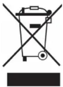
DISPOSAL CONSIDERATIONS
natural_image
Symbol of a trash bin crossed with a diagonal line, no text or numbers presentIf there is a legal regulation for the disposal of electrical and electronic devices in your country, this symbol on the product or on the packaging indicates that this product must not be disposed of with household waste. Instead, it must be taken to a collection point for the recycling of electrical and electronic equipment. By disposing of it in accordance with the rules, you are protecting the environment and the health of your fellow human beings from negative consequences. For information about the recycling and disposal of this product, please contact your local authority or your household waste disposal service.
DECLARATION OF CONFORMITY

Manufacturer:
Chal-Tec GmbH, Wallstrasse 16, 10179 Berlin, Germany.
Importer for Great Britain:
Berlin Brands Group UK Limited PO Box 42
272 Kensington High Street London, W8 6ND United Kingdom
Hereby, Chal-Tec GmbH declares that the radio equipment type Circle Smart is in compliance with Directive 2014/53/EU. The full text of the EU declaration of conformity is available at the following internet address: use.berlin/10045542
For Great Britain: Hereby, Chal-Tec GmbH declares that the radio equipment type Circle Smart is in compliance with the relevant statutory requirements. The full text of the declaration of conformity is available at the following internet address: use.berlin/10045542
Chère cliente, cher client,
SOMMAIRE
Fiche technique 41
Mises en garde 42
UTILISATION
Panneau de commande

1. POWER
natural_image
Diagram of a mechanical device with a black arrow pointing to a component, no text or symbols presentVidange continue
natural_image
Line drawing of a portable air conditioner unit with attached battery (no text or symbols)Retrait du filtre
natural_image
Symbol of a trash bin crossed with a diagonal line, no text or numbers presentDÉCLARATION DE CONFORMITÉ

Fabricant :
Chal-Tec GmbH, Wallstraße 16, 10179 Berlin, Allemagne.
Berlin Brands Group UK Limited PO Box 42
272 Kensington High Street
London, W8 6ND
United Kingdom
INDICE
Dati tecnici 59
Avvertimenti 60
UTILIZZO
natural_image
Diagram of a device with a black arrow pointing to a component, showing no text or symbols.natural_image
Line drawing of a mechanical device with a housing and connecting rod (no text or symbols)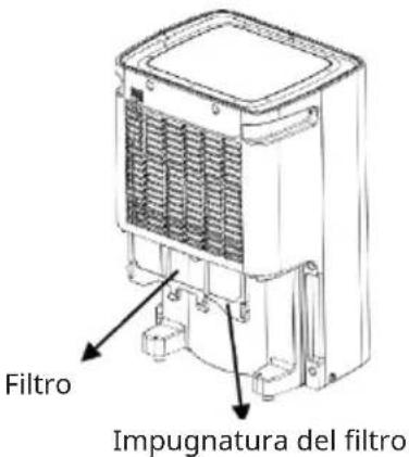
MANUTENZIONE
natural_image
Symbol of a trash bin crossed with a diagonal line, no text or numbers presentBerlin Brands Group UK Limited PO Box 42
272 Kensington High Street
London, W8 6ND
United Kingdom
CONTENIDO
Datos técnicos 77
Advertencias 78
FUNCIONAMIENTO
Panel de control

1. POWER
natural_image
Diagram of a device with a black arrow pointing to a component, showing no text or symbols.Drenaje continuo
natural_image
Technical line drawing of a portable air conditioner unit with cooling fins and a battery (no text or symbols)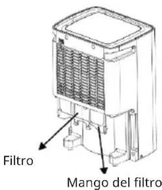
MANTENIMIENTO
natural_image
Symbol of a trash bin crossed with a diagonal line, no text or numbers presentBerlin Brands Group UK Limited
PO Box 42
272 Kensington High Street
London, W8 6ND
United Kingdom

- INHALT
- BEDIENUNG
- Bedienfeld
- POWER
- Filter-Entfernung
- CONTENTS
- TECHNICAL DATA
- WARNINGS
- SAFETY INSTRUCTIONS
- TRANSPORT, MARKING AND STORAGE
- Transportation
- Marking and disposal
- Storage
- General working area
- PRODUCT OVERVIEW
- OPERATION
- FAN SPEED
- TIMER
- Humidity setting
- Wi-Fi indicator
- Comfort mode
- Notes
- DEVICE CONTROL BY SMARTPHONE
- Follow these steps to connect your smartphone to your Klarstein device:
- App Download
- Troubleshooting connection problems
- DRAINING INSTRUCTION
- Usage of water tank
- Continuous drainage
- Filter removal
- MAINTENANCE
- Information on servicing
- WARNING Risk of electric shock or other personal injury!
- 1) Checks to the area
- 2) Work procedure
- 3) Checking for presence of refrigerant
- 4) Presence of fire extinguisher
- 5) No ignition sources
- 6) Ventilated area
- 7) Checks to the refrigeration equipment
- The following checks shall be applied to installations using flammable refrigerants:
- 8) Checks to electrical devices
- Repairs to sealed components
- Repair to intrinsically safe components
- Cabling
- Detection of flammable refrigerants
- Leak detection methods
- Removal and evacuation
- Charging procedures
- DECOMMISSIONING
- Labelling
- Recovery
- Error Codes
- DISPOSAL CONSIDERATIONS
- DECLARATION OF CONFORMITY
- Manufacturer:
- Importer for Great Britain:
- Chère cliente, cher client,
- SOMMAIRE
- UTILISATION
- Panneau de commande
- Vidange continue
- Retrait du filtre
- DÉCLARATION DE CONFORMITÉ
- Fabricant :
- INDICE
- UTILIZZO
- MANUTENZIONE
- CONTENIDO
- FUNCIONAMIENTO
- Drenaje continuo
- MANTENIMIENTO
Brand : Klarstein
Model : CircleDry Smart
Category : Dehumidifier