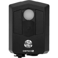
UNISENS - Audio Interface Cameo - Free user manual and instructions
Find the device manual for free UNISENS Cameo in PDF.


| Product type | Ambient light sensor / DMX interface |
| Brand | Cameo |
| Model | UNISENS |
| Dimensions (W x H x D) | 126 x 92 x 43 mm |
| Weight | 0.44 kg |
| Protection rating | IP65 |
| Power supply | Lithium-ion battery 3000 mAh, recharge via USB-C (5 V, 500 mA recommended) |
| Battery life | >20 hours |
| Charging time | Approximately 8 hours |
| Control protocols | DMX512, RDM |
| Connectors | XLR 5-pin male (DMX IN), XLR 5-pin female (DMX OUT), USB-C (charging) |
| Main functions | Light color measurement (X/Y coordinates), light intensity measurement, continuous and One Shot mode, DMX merge |
| User interface | Haptic button with multicolored LED ring |
| Photometric accuracy | <5 % |
| Colorimetric accuracy | <2 % |
| Ambient temperature range | -10 °C to +40 °C |
| Mounting | 1/4 inch thread for tripod, eyelet for wrist strap |
| Maintenance and cleaning | Clean the sensor with a soft damp cloth or optical brush; clean the housing with a clean damp cloth. Do not use abrasive products. |
| Safety | IP65, lithium-ion battery with protection, do not open the device, avoid heat sources and shocks |
| Spare parts and repairability | No user-serviceable parts. Repair only by qualified authorized personnel. |
| Package contents | 1 × UNISENS sensor, 1 × USB-A to USB-C cable, safety information |
Frequently Asked Questions - UNISENS Cameo
User questions about UNISENS Cameo
0 question about this device. Answer the ones you know or ask your own.
Ask a new question about this device
Download the instructions for your Audio Interface in PDF format for free! Find your manual UNISENS - Cameo and take your electronic device back in hand. On this page are published all the documents necessary for the use of your device. UNISENS by Cameo.
USER MANUAL UNISENS Cameo
natural_image
Black camera module with circular lens and control buttons, no visible text or symbols on the device itself.UNISENS®
AMBIENT LIGHT TO DMX INTERFACE
CLUNISENS
CONTENTS / INHALTSVERZEICHNIS / CONTENU / CONTENIDO / TREŚĆ / CONTENUTO
ENGLISH
INFORMATION ON THIS USER MANUAL 6
INTENDED USE 6
EXPLANATIONS OF TERMS AND SYMBOLS 6
SAFETY INSTRUCTIONS 7
NOTES ON PORTABLE OUTDOOR DEVICES 11
PACKAGING CONTENT 11
INTRODUCTION 11
CONNECTIONS AND OPERATING/DISPLAY ELEMENTS 12
APPLICATION EXAMPLES 14
ADDITIONS TO THE DEVICE MENU AND ADDITIONAL DMX MODE FOR 16
COMPATIBLE FIXTURES 16
CARE, MAINTENANCE, AND REPAIR 19
TECHNICAL DATA 20
EXPLANATION OF IP PROTECTION CLASS 21
DISPOSAL 21
MANUFACTURER'S DECLARATIONS 22
DEUTSCH
You have made the right choice!
This device has been developed and manufactured to the highest quality standards to ensure many years of trouble-free operation. Please read this user manual carefully to be able to quickly put your new Cameo Light product to optimum use. Further information about Cameo Light is available on our website CAMEOLIGHT.COM
INFORMATION ON THIS USER MANUAL
- Carefully read the safety instructions and the entire manual before operating the device.
- Observe the warnings on the device and in the user manual.
• Always keep the user manual within reach. - If you sell or pass on the device, it is important that you also include this user manual, as it is an integral part of the product.
INTENDED USE
This product is a device for event technology!
This product has been developed for professional use in the field of event technology and is not suitable for use as domestic lighting!
Furthermore, this product is only intended for qualified users with specialist knowledge of temporary operation! Event equipment is generally designed for temporary use only and not for continuous operation and fixed installation! Intended for event technology!
Use of the product that is not in accordance with the specified technical data and operating conditions is considered improper use!
Liability is exempted when damage and third-party damage to persons and property is caused by inappropriate use!
The product is not suitable for:
- Persons (including children) with limited physical, sensory, or mental abilities or lack of experience and knowledge.
- Children (children must be instructed not to play with the device).
EXPLANATIONS OF TERMS AND SYMBOLS
-
DANGER: The word DANGER, possibly in combination with a symbol, indicates immediately hazardous situations or conditions for life and limb.
-
WARNING: The word WARNING, possibly in combination with a symbol, indicates potentially hazardous situations or conditions for life and limb.
-
CAUTION: The word CAUTION, possibly in combination with a symbol, indicates situations or conditions that may lead to injury.
-
ATTENTION: The word ATTENTION, possibly in combination with a symbol, indicates situations or conditions that may lead to damage to property and/or the environment.
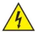
This symbol identifies hazards that can cause electric shock.

This symbol indicates hazardous areas or hazardous situations.

This symbol indicates hazards caused by hot surfaces.
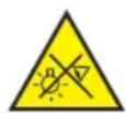
This symbol indicates hazards caused by intense light sources.

This symbol indicates a device in which there are no user-replaceable parts.

This symbol indicates additional information on the operation of the product.
SAFETY INSTRUCTIONS
DANGER:
- Do not open the device, and do not make any modifications to it.
- If your device no longer functions properly, if liquids or objects get inside it, or if it has been damaged in any other way, switch it off immediately and disconnect it from the power supply. The device may be repaired only by authorised qualified personnel.
- For devices of protection class 1, the protective conductor must be connected correctly. Never disconnect the protective conductor. Devices of protection class 2 do not have a protective conductor.
- Ensure that live cables are not kinked or otherwise mechanically damaged.
- Never bypass the device fuse.
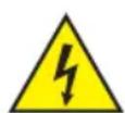
WARNING:
- The device may not be operated if it shows obvious signs of damage.
- The device may only be installed in a voltage-free state.
- If the device's mains cable is damaged, the device may not be operated.
- Permanently attached mains cables may only be replaced by a qualified person.
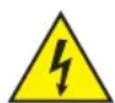
ATTENTION:
- Do not operate the device if it has been exposed to large temperature fluctuations (for example, after transport). Moisture and condensation may damage the device. Switch on the device only when it has reached ambient temperature.
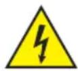
- Make sure that the voltage and frequency of the mains correspond to the values specified on the device. If the device has a voltage selector switch, do not connect the device until it has been set correctly. Use only suitable mains cables.
- To disconnect the device from the mains at all poles, it is not sufficient to press the on/off switch on the device.
- Make sure that the fuse used corresponds to the type specified on the device.
- Make sure that appropriate measures have been taken against power surges (for example, lightning strike).
- Observe the specified maximum output current on devices with Power Out connection. Ensure that the total current consumption of all connected devices does not exceed the specified value.
- Replace plug-in mains cables only with original cables.

DANGER:
- Danger of suffocation/choking! Plastic bags and small parts must be kept out of reach of persons (including children) with reduced physical, sensory, or mental capabilities.
- Danger caused by falling device! Make sure that the device is securely installed and cannot fall down. Only use suitable stands or mounts (particularly for fixed installations). Ensure that accessories are properly installed and secured. Ensure that applicable safety regulations are observed.

WARNING:
- Use the device only in the prescribed manner.
- Operate the device only with the accessories recommended and intended by the manufacturer.
- During installation, observe the safety regulations applicable in your country.
- After connecting the device, check all cable routes to avoid damage or accidents, for example, due to tripping hazards.
- Always observe the specified minimum distance to normally flammable materials! Unless explicitly stated, the minimum distance is 0.3 m.
- Always observe the minimum distance to the illuminated surface specified on the device!

CAUTION:
- Moving components such as mounting brackets or other movable components may become jammed.
- Devices with motor-driven components may result in injury from the movement of the device. Sudden movement of the device can cause electric shock.

ATTENTION:
- Do not install or operate the device near any radiators, heat registers, stoves, or other heat sources. Ensure that the device is always installed in such a way that it is sufficiently cooled and cannot overheat.
- Do not place ignition sources such as burning candles near the device.
- Ventilation openings must not be covered, and fans must not be blocked.
- Use the original packaging or packaging provided by the manufacturer for transport.
- Avoid shock or impact to the device.
- Observe the IP protection class, as well as the ambient conditions such as temperature and humidity according to the specification.
- Devices can be constantly further developed. In the event of deviating information on operating conditions, performance, or other device properties between the user manual and the device labelling, the information on the device always takes priority.
- The device is not suitable for tropical climates and for operation at heights of 2,000 m above sea level or higher.
- Unless explicitly stated, the device is not suitable for operation in marine conditions.

PLEASE NOTE:
For conversion or retrofit sets or accessories provided by the manufacturer, it is essential to observe the included instructions.

BATTERY DEVICES AND CHARGERS:
- Keep the battery-powered device away from heat sources, and do not expose it to direct sunlight. Do not place it on or in heating appliances such as microwaves, ovens, or radiators. Batteries can explode if overheated. Always observe the care instructions and ensure the ambient conditions are appropriate! These are detailed in the technical specifications.
- Do not open the device! Do not modify the battery, and do not attempt to replace the battery cells!
- Battery cells or battery packs must not be damaged. Do not remove any protective film or stickers. Do not insert any foreign objects into the battery. Do not allow liquids to get into the battery. There is a risk of fire and explosion as well as other dangerous situations (for example, outgassing).
- If the device becomes deformed or overheats, stop using it immediately! If you continue to operate the device, there is a danger of fire and explosion as well as a danger of other hazardous situations (for example, outgassing).
- Do not throw the device into a fire! Danger of explosion!
- Do not subject the device to strong mechanical effects! Damage caused by falling, crushing, or piercing, as well as high pressure, leads to a danger of fire and explosion as well as a danger of other hazardous situations (for example, outgassing).

- Only charge the device or battery in the intended manner.
- Please note that device's main switch does not deactivate the charging function on all devices.
- In the case of charging devices built into transport cases, charging may only be carried out when the lid is open.
- Leaked fluid is corrosive and can be toxic. It can cause skin and eye irritations and is dangerous if swallowed. Avoid any contact with leaked fluid. In the event of contact with leaked fluid, immediately wash the affected area with plenty of water and contact a doctor.

CHARGING, USING, AND STORING BATTERIES
- To charge permanently installed batteries, connect the device to the correct power supply. Please note that the device's main switch does not deactivate the charging function on all devices.
- The charging time for a full charge of the battery can be found in the technical data. For information on how to display the battery charge status, see chapter OPERATION.
- Devices with lithium batteries are equipped with standard protective features.
- Do not charge the battery outside the ambient conditions specified in the technical data. Unless otherwise specified, these are between +5^ and +35^ Celsius in dry environments.
- The permissible ambient conditions for operation can be found in the technical data. Unless otherwise specified, these must not be below +5°C or above +35°C in dry environments.
- The permissible ambient conditions for storage can be found in the technical data. Unless otherwise specified, these must not be below +5°C or above +35°C in dry environments.
- Fully recharge the battery immediately after discharge.
- Only store the device with a fully charged battery. Batteries that are not fully charged may lose capacity and service life prematurely.
- If the device is not to be used for a longer period of time, perform a full discharge and charge cycle no later than every three months.
- The device's main switch must be switched off during storage.
- The battery operating times specified always refer to a new battery and normal operating conditions.
- The battery operating time may be shorter than specified when operated in cold environments.
- If the operating time of the device in battery operation deviates significantly from the specifications, please contact your distribution partner.

NOTES ON PORTABLE OUTDOOR DEVICES
- Temporary operation! Event equipment is generally only designed for temporary operation.
- Continuous operation or permanent structural installation – particularly outdoors – can impair the function, surfaces, and seals and cause premature material fatigue.
- Damage to the surface coating can impair the device's corrosion protection. Damaged surface coating (for example, scratches) must be promptly repaired using suitable measures.
PACKAGING CONTENT
Remove the product from the packaging, and remove all packaging material.
Please check the completeness and integrity of the delivery and notify your distribution partner immediately after purchase if the delivery is not complete or if it is damaged.
The packaging content for the product includes:
▶ 1 × UNISENS Ambient Light to DMX Interface
▶ 1 × USB-A to USB-C cable
▶ Safety and compliance information (user manual as a download via QR code)
INTRODUCTION
The battery-operated Cameo UNISENS with IP65 protection is an ambient light sensor that records various lighting parameters and makes them available via DMX. The DMX merge function makes it possible to integrate the device into a system as required. It is operated using a button with a multi-coloured LED ring to identify the operating mode. Configuration is carried out via RDM; the in-house controller Cameo UNICON is recommended for this.
Compatible fixtures have a special DMX mode for control via UNISENS.
CONNECTIONS AND OPERATING/DISPLAY ELEMENTS
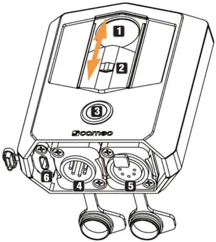
1 LIGHT SENSOR
Make sure that the sensor is free of dust and dirt and does not have any scratches. Dirt and damage hinder the accuracy of measurements. If necessary, clean the sensor with a damp, soft cloth or an optical brush.
2 PROTECTIVE COVER
Slide the protective cover over the sensor when the device is not in use.
3 ON/OFF SWITCH (BUTTON) WITH LED INDICATOR RING
Press and hold the button for approximately three seconds to turn the device on and off.
The LED ring shows the following operating statuses:
Blue = Continuous mode (permanent measurement)
Green = One-shot measurement (measurement at the touch of a button)
Magenta = Continuous mode (permanent measurement) and charging of battery
Yellow = One-shot measurement (measurement at the touch of a button) and charging of battery
Red = Device switched off, charging of battery (LED ring off = battery fully charged, please unplug charger)
Switch mode: double-click
4 DMX IN
Male IP65 5-Pol XLR socket for connecting a RDM/DMX control device, for example, Cameo UNI-CON (when not in use, always close the rubber sealing cap).
5 DMX OUT
Female IP65 5-Pol XLR socket for outputting the DMX control signal (when not in use, always close the rubber sealing cap).
6 USB-C CHARGING SOCKET
Charging socket for charging the internal battery. For this purpose, commercially available 5 V chargers with a USB-C plug can be used (charging status visible in Cameo UNICON)

natural_image
Technical line drawing of a rectangular electronic component with labeled parts (7 and 8), no readable text or symbols beyond labels7 MOUNTING EYELET
Eyelet for attaching a carrying loop.
8 TRIPOD THREADS
Use the 1/4 inch thread to mount the device on a suitable tripod (for example, camera tripod).
APPLICATION EXAMPLES
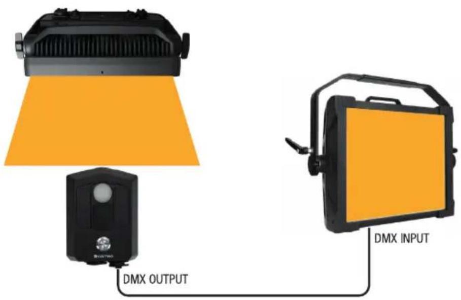
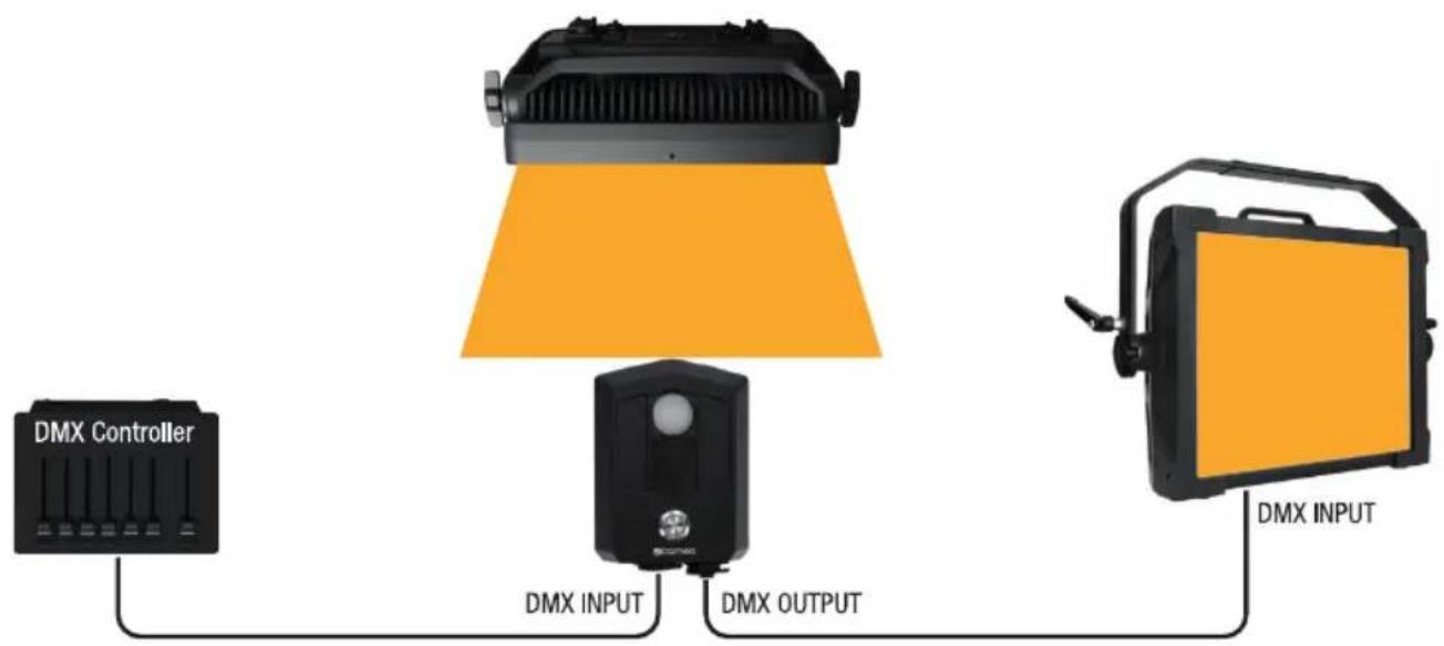
Point the sensor of the UNISENS directly at the light source to be measured during the measurement process.
- UNISENS measures the light colour; the fixture reproduces the measured light colour. The brightness is set manually on the fixture.
- UNISENS measures the light colour; the fixture reproduces the measured light colour. The brightness is set via a DMX controller.
flowchart
graph LR
    A["DMX Controller"] --> B["DMX INPUT"]
    B --> C["DMX OUTPUT"]
    C --> D["DMX INPUT"]
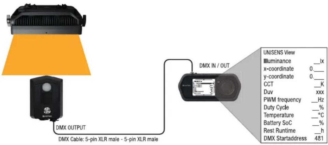
- UNISENS measures the light source; UNICON displays the measured values (select and confirm UNISENS View in the UNICON main menu. Always keep the UNICON firmware up to date). The DMX start address of the UNISENS is set to 481 by default for the light source's measurement data to be displayed in the UNICON. The DMX start address, however, can be customised (see point 4).
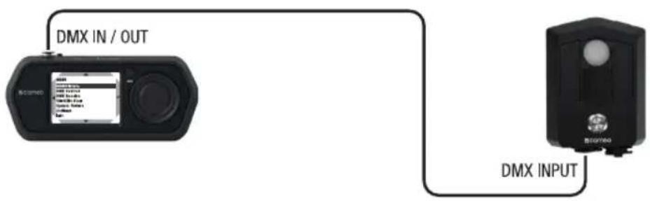
- Change the DMX start address and operating mode of the UNISENS via UNICON (MENU -> RDM/Fixture -> DMX Address or DMX Mode).
flowchart
graph TD
    A["SCameo"] -->|DMX IN / OUT| B["Device 1"]
    A -->|DMX INPUT| C["Device 2"]
ADDITIONS TO THE DEVICE MENU AND ADDITIONAL DMX MODE FOR COMPATIBLE FIXTURES
1. Fixture with three-encoder operation
Applies to the following fixtures with serial number EKxxxx0521 (= May 2021) or newer:
CLIREMOTE V1.3
S2 IP V1.3
S4 IP V1.7
P2 FC V1.2
F1 FC V1.6
F2 FC V1.6
F2 FC+ V1.2
F2 FC IP V1.7
F2 FC P0 V1.6
F4 FC V1.6
F4 FC P0 IP V1.6

Fixtures with serial numbers before May 2021 can be updated, but do not have the Colour Coordinates operating mode.
COLOURCOORDINATES STAND-ALONE OPERATING MODE
Manual control:
Starting from the main screen, press the left rotary-push encoder to access the menu for selecting the operating mode (Mode). Rotate the left encoder (SELECT) to select Colour Coordinates and confirm by pressing the left encoder (ENTER). Now select By User and confirm again. Then set the brightness (DIM) and the x- and y-coordinates using the three rotary-push encoders (see table).
| Manual control via encoder | |||
| Left encoder Centre encoder | Right encoder | ||
| Rotate: Adjust brightness | Set digits 1 and 2 after the decimal point | Set digits 3 and 4 after the decimal point | |
| Press: Select operating mode | Switch between x and y | Open main menu | |
Control via UNISENS:
Starting from the main screen, press the left rotary-push encoder to access the menu for selecting the operating mode (Mode). Rotate the left encoder (SELECT) to select Colour Coordinates
(note the selection arrow on the left) and confirm by pressing the left encoder (ENTER). Now select By UNISENS and confirm again. Connect the UNISENS to the fixture as shown in the illustration. The colour coordinates are now controlled via UNISENS, and the values are shown on the display. The brightness is set by rotating the left encoder (DIM).
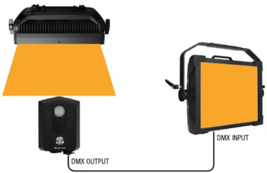
| Control via UNISENS and encoder | |||
| Left encoder Centre encoder | Right encoder | ||
| Rotate: Adjust brightness – – | |||
| Press: Select operating mode | Switch view between x and y | Open main menu | |
2. Fixture with four-button control
Applies to the following fixtures:
CLH2FC (V firmware and up; TBD)
CLUXISFC (V firmware and up; TBD)
COLOURCOORDINATES STAND-ALONE OPERATING MODE
Manual control:
Starting from the main display, press MENU to access the main menu. Using UP and DOWN, now select the menu item Stand Alone, confirm with ENTER, then select Colour Coordinates, and confirm once again. Now select By User and confirm again.
This will take you to the sub-menu for setting the sub-menu items (see table, select with UP and DOWN, confirm with ENTER, change value with UP and DOWN, confirm with ENTER).
| Manual control via operating elements | ||
| Dimmer 0–100 | Adjust the brightness | |
| X-coordinate 0 | 0.0000–0.8500 Set | the x coordinate |
| Y-coordinate | 0.0000–0.8500 Set | the y-coordinate |
Control via UNISENS:
Starting from the main display, press MENU to access the main menu. Using UP and DOWN, now select the menu item Stand Alone, confirm with ENTER, then select Colour Coordinates, and confirm once again. Now select By UNISENS and confirm again. Connect the UNISENS to the fixture as shown in the illustration. The colour coordinates are now controlled via UNISENS, and the values are shown on the display. You can set the brightness of the fixture in the Dimmer menu item.
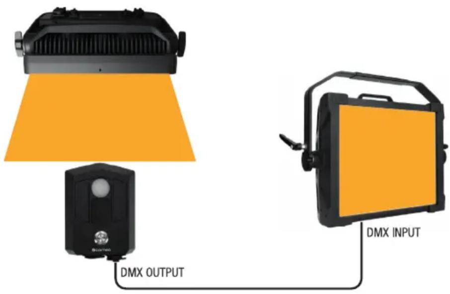
Manual control via UNISENS and operating elements
Dimmer 0–100 Adjust the brightness
3. Fixture without display, operation via UNICON
Applies to the following fixtures:
CLH1FC (V firmware and up; TBD)
COLOUR COORDINATES STAND-ALONE OPERATING MODE
Manual control:
Connect the UNICON directly to the fixture. In the UNICON, select Stand Alone in the device menu of the fixture, confirm the selection, select Colour Coordinates, and confirm again. Now select the menu item you wish to edit and confirm the selection. Set the desired value and confirm the entry.
| Manual control via UNICON | ||
| Dimmer 0–100 Adjust the brightness | ||
| X-coordinate 0.0000–0.8500 Set the x-coordinate | ||
| Y-coordinate 0.0000–0.8500 Set the y-coordinate | ||
ADDITIONAL DMX MODE
| 2CH UNISENS | ||||
| Channel mode Function Values | ||||
| 1 Dimmer 000 – 255 0%–100% | ||||
| 2 Dimmer fine 000 – 255 | ||||
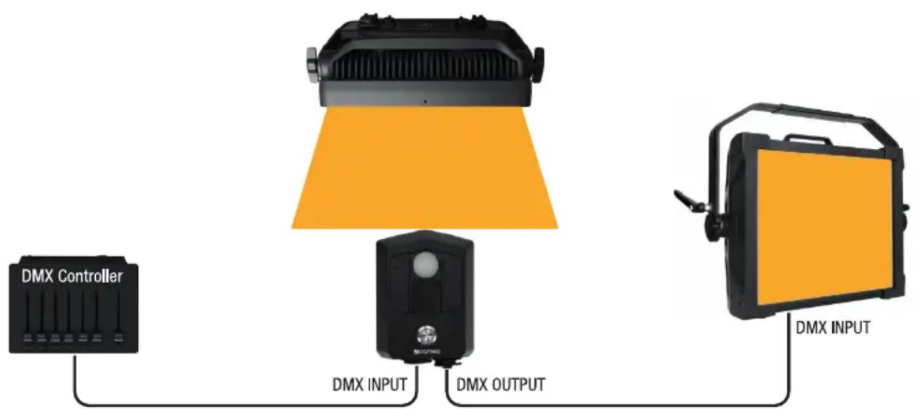
flowchart
graph LR
    A["DMX Controller"] --> B["DMX INPUT"]
    B --> C["DMX OUTPUT"]
    C --> D["DMX INPUT"]
CARE, MAINTENANCE, AND REPAIR
In order to ensure the long-term, proper functioning of the device, it must be regularly cleaned and, if necessary, serviced. The care and maintenance required depends on the intensity of use and the environment in which it is used.
We recommend a visual inspection before each operation. Furthermore, we recommend carrying out all the applicable service measures specified below once every 500 operating hours or, in the case of a lower intensity of use, at the latest after one year. Warranty claims may be limited should defects result from inadequate service and maintenance.
CARE (carried out by user)
WARNING! Before carrying out any care or maintenance, the power supply – and, if possible, all device connections – must be disconnected.

PLEASE NOTE! Improper care can lead to impairment of the device or even its destruction.
- Housing surfaces must be cleaned with a clean, damp cloth. Make sure that no moisture can penetrate the device.
- Air inlets and outlets must be regularly cleaned of dust and dirt. If compressed air is used, make
sure that damage to the device is prevented (for example, fans must be blocked in this case, as they could otherwise over-rev).
- Cables and connectors must be cleaned regularly, and dust and dirt must be removed.
- In general, no cleaning agents or abrasive agents may be used; otherwise, the surface finish may be damaged.
- Devices must be stored in a dry environment and protected from dust and dirt.
MAINTENANCE AND REPAIR (by qualified personnel only)
DANGER! There are live components in the device. Even after disconnecting from the mains, there may still be residual voltage in the device, for example, due to charged capacitors.

PLEASE NOTE! There are no user-serviceable assemblies in the device.

PLEASE NOTE! Maintenance and repair work may only be carried out by qualified specialist personnel authorised by the manufacturer. If in doubt, consult the manufacturer.

PLEASE NOTE! Improperly performed maintenance work may affect warranty claims.
TECHNICAL DATA
| Item number | CLUNISENS |
| Product category | Spotlight accessory |
| Type | Ambient Light to DMX Interface |
| Control protocols | DMX512; RDM |
| Data connections | XLR 5 pin male and female |
| User interface | One haptic button with colored backlight |
| Battery type | Li-lon battery |
| Battery capacity | 3000 mAh |
| Battery charging time | 8 h |
| Battery runtime | >20 h |
| Charging voltage | 5 V |
| Recommended charging current | 500 mA |
| Power connection | USB-C |
| Ambient temperature rating | -10° - 40°C |
| IP rating | IP65 |
| Photometric accuracy | <5% |
| Colormetric accucary | <2% |
| RDM UID | 0x08A40600XXXX |
| Dimensions | 126 x 92 x 43 mm |
| Weight | 0.44 kg |
| Accessories included | USB-A to USB-C cable |
EXPLANATION OF IP PROTECTION CLASS
- An IP rating only reflects protection from solid objects and water. It does not describe general weather resistance, such as protection from UV radiation and temperature, etc.
- The first digit indicates protection from dust, solid objects and contact:
| IP2X | Protected against solid foreign objects ≥ 12.5 mm in diameter |
| IP3X | Protected against solid foreign objects ≥ 2.5 mm in diameter |
| IP4X | Protected against solid foreign objects ≥ 1.0 mm in diameter |
| IP5X | Protected against dust in harmful quantities and completely protected against contact |
| IP6X | Dust-tight and completely protected against contact |
- The second digit indicates protection against water:
| IPX0 | No protection |
| IPX1 | Protection against dripping water |
| IPX2 | Protection against dripping water when the device is tilted by up to 15° |
| IPX3 | Protection against falling spray water up to 60° from the vertical |
| IPX4 | Protection against splashing water on all sides |
| IPX5 | Protection against water jets (nozzle) from any angle |
| IPX6 | Protection against strong water jets |
| IPX7 | Protection against temporary immersion |
- In addition, some device-specific measures such as covers and sealing caps are necessary in order to achieve the specified protection class (for example, protective caps on unused connectors).

The product's IP protection class can be found in the technical data and is printed on the device.
DISPOSAL

PACKAGING:
- Packaging can be recycled using the usual disposal methods.
- Please separate the packaging in accordance with the disposal laws and recycling regulations in your country.
DEVICE:
- This device is subject to the European Directive on Waste Electrical and Electronic Equipment, as amended. WEEE Directive Waste Electrical and Electronic Equipment. Waste equipment does not belong in household waste. Waste equipment must be disposed of via an authorised waste disposal company or a municipal waste disposal facility. Please observe the applicable regulations in your country!
- Observe all disposal laws applicable in your country.
- As a private customer, you can obtain information on environmentally friendly disposal options from the seller of the product or the appropriate regional authorities.
MANUFACTURER'S DECLARATIONS
Manufacturer's warranty and limitation of liability
Adam Hall GmbH | Adam-Hall-Str.1 | 61267 Neu-Anspach | Germany
Email: Info@adamhall.com / +49 (0)6081 / 9419-0
Our current warranty conditions and limitation of liability can be found at:
https://cdn-shop.adamhall.com/media/pdf/Manufacturers-Declarations-CAMEO_DE_EN_ES_FR.pdf
For service requests, please contact your distribution partner.
CE conformity
Adam Hall GmbH hereby confirms that this product meets the following guidelines
(where applicable):
Low-Voltage Directive (2014/35/EU)
EMC Directive (2014/30/EU)
RoHS (2011/65/EU)
RED (2014/53/EU)
EC Declaration of Conformity
Declarations of conformity for products subject to the LVD, EMC, and RoHS Directives can be requested from info@adamhall.com
Declarations of conformity for products subject to RED can be downloaded from www.adamhall.com/compliance/
Subject to misprints and errors, as well as technical or other modifications!
DEUTSCH
natural_image
Technical line drawing of a rectangular electronic device with labeled parts (no text or symbols beyond numbers)7 EINHÄNGESE
1 CAPTEUR DE LUMIÈRE
natural_image
Technical line drawing of a rectangular electronic device with labeled parts (no text or symbols beyond numbers)7 OELLET DE FIXATION
https://cdn-shop.adamhall.com/media/pdf/Manufacturers-Declarations-CAMEO_DE_EN_ES_FR.pdf.
Directive CEM (2014/30/UE)
RoHS (2011/65/UE)
RED (2014/53/UE)
▶ 1 × Cable USB-A a USB-C
natural_image
Technical line drawing of a rectangular electronic device with labeled parts (7, 8), no readable text or symbols beyond labels7 CÁNCAMO DE ENGANCHE
https://cdn-shop.adamhall.com/media/pdf/Manufacturers-Declarations-CAMEO_DE_EN_ES_FR.pdf
natural_image
Technical line drawing of a rectangular electronic device with labeled parts (no text or symbols beyond numbers)7 OCZKO DO ZAWIESZANIA
https://cdn-shop.adamhall.com/media/pdf/Manufacturers-Declarations-CAMEO_DE_EN_ES_FR.pdf
1 SENSORE DI LUCE
natural_image
Technical line drawing of a rectangular electronic device with labeled parts (7, 8), no readable text or symbols beyond labels7 OCCHIELLO DI SOSPENSIONE
https://cdn-shop.adamhall.com/media/pdf/Manufacturers-Declarations-CAMEO DE EN ES FR.pdf


- UNISENS®
- CONTENTS / INHALTSVERZEICHNIS / CONTENU / CONTENIDO / TREŚĆ / CONTENUTO
- ENGLISH
- DEUTSCH
- INFORMATION ON THIS USER MANUAL
- INTENDED USE
- EXPLANATIONS OF TERMS AND SYMBOLS
- SAFETY INSTRUCTIONS
- DANGER:
- WARNING:
- ATTENTION:
- CAUTION:
- PLEASE NOTE:
- BATTERY DEVICES AND CHARGERS:
- CHARGING, USING, AND STORING BATTERIES
- NOTES ON PORTABLE OUTDOOR DEVICES
- PACKAGING CONTENT
- INTRODUCTION
- CONNECTIONS AND OPERATING/DISPLAY ELEMENTS
- LIGHT SENSOR
- PROTECTIVE COVER
- ON/OFF SWITCH (BUTTON) WITH LED INDICATOR RING
- DMX IN
- DMX OUT
- USB-C CHARGING SOCKET
- MOUNTING EYELET
- TRIPOD THREADS
- APPLICATION EXAMPLES
- ADDITIONS TO THE DEVICE MENU AND ADDITIONAL DMX MODE FOR COMPATIBLE FIXTURES
- Fixture with three-encoder operation
- COLOURCOORDINATES STAND-ALONE OPERATING MODE
- Manual control:
- Control via UNISENS:
- Fixture with four-button control
- Fixture without display, operation via UNICON
- COLOUR COORDINATES STAND-ALONE OPERATING MODE
- ADDITIONAL DMX MODE
- CARE, MAINTENANCE, AND REPAIR
- CARE (carried out by user)
- MAINTENANCE AND REPAIR (by qualified personnel only)
- EXPLANATION OF IP PROTECTION CLASS
- DISPOSAL
- PACKAGING:
- DEVICE:
- MANUFACTURER'S DECLARATIONS
- Manufacturer's warranty and limitation of liability
- CE conformity
- EC Declaration of Conformity
- EINHÄNGESE
- CAPTEUR DE LUMIÈRE
- OELLET DE FIXATION
- CÁNCAMO DE ENGANCHE
- OCZKO DO ZAWIESZANIA
- SENSORE DI LUCE
- OCCHIELLO DI SOSPENSIONE
Brand : Cameo
Model : UNISENS
Category : Audio Interface