K-408 - Faucet KOHLER - Free user manual and instructions
Find the device manual for free K-408 KOHLER in PDF.

| Product Type | Bathtub/Shower Transfer Valve |
| Brand | Kohler |
| Model | K-408 |
| Body Material | Brass |
| Cartridge Material | Plastic |
| Maximum Countertop Thickness | 1-7/16" (3.7 cm) |
| Pass-through Hole Diameter | 2" (5 cm) |
| Estimated Weight | 1.2 kg |
| Supply | Hot and Cold Water |
| Number of Ways | 3-way (convertible to 2-way) |
| Functions | Transfer valve with built-in vacuum breaker, auxiliary outlet, handshower |
| Connection Type | Solder (copper) or threaded (depending on configuration) |
| Maintenance | Clean with a soft cloth and soapy water; avoid abrasive cleaners |
| Safety Precautions | Do not use petroleum-based lubricants on plastic parts; avoid direct flame on brass body |
| Replacement Parts Available | Cartridge, stop collars (gray 3-way, black 2-way), plated nut, o-rings |
| Repairability | Replaceable cartridge without disassembling plumbing |
| Installation Tools Required | Screwdriver, adjustable wrench, plumber's putty, torch, hacksaw, Teflon tape |
| Standards | Comply with local plumbing and building codes |
| Included Accessories | Gray 3-way stop collar (pre-assembled) and black 2-way collar |
Frequently Asked Questions - K-408 KOHLER
User questions about K-408 KOHLER
0 question about this device. Answer the ones you know or ask your own.
Ask a new question about this device
Download the instructions for your Faucet in PDF format for free! Find your manual K-408 - KOHLER and take your electronic device back in hand. On this page are published all the documents necessary for the use of your device. K-408 by KOHLER.
USER MANUAL K-408 KOHLER
Two-Way/Three-Way Valve
K-408 K-409

Mproduct numbers are for Mexico (i.e. K-12345M)
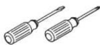
Assorted
Screwdrivers
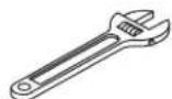
Adjustable Wrench

Plumbers
Putty
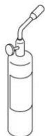
Propane Torch
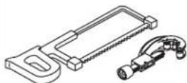
Hacksaw or
Tubing Cutter

Solder

Sealant Tape
Before You Begin

CAUTION: Riskofpropertydamage. When installed in a two-way configuration, the auxiliary outlet must be capped off to prevent possible leakage out of the unused auxiliary outlet, and the grey collar must be changed to the black two-way stop collar.

CAUTION: Riskofproductdamage. The transfer valve is designed for use with Kohler non-diverting bath spouts. Do not use diverters, diverter spouts, or shut-off devices downstream of the transfer valve.

CAUTION: Riskofproductdamage. Do not use petroleum-based lubricants on the plastic components of this valve.

CAUTION: Riskofproductdamage. Excessive heat will damage the internal plastic components. Follow these steps to avoid product damage.
IMPORTANT! Do not apply excessive heat while soldering. Direct the torch flame away from the brass body.
IMPORTANT! Only apply direct heat to the connectors and extensions.
IMPORTANT! If there is limited access to the solder connections, or if any other risk of excessive heat being applied to the brass body exists, remove the cartridge prior to soldering. If you remove the cartridge, protect the seals and O-rings from becoming dirty, damaged, or misaligned.
Before You Begin (cont.)
IMPORTANT! A main valve must be installed upstream from the diverter valve for shut off and temperature control.
□ Observe all local plumbing and building codes.
□ Shut off the main water supply.
□ Provide an access panel for all installations.
□ Carefully read this entire instruction manual before beginning the installation; the illustrations do not show all possible configurations.
☐ ForK-408: This valve can be installed to decks with a maximum thickness of no more than 1-7/16"(3.7 cm).
☐ ForK-409: This valve can be installed to decks with a maximum thickness of no more than 3-7/16"(8.7 cm).
☐ The transfer valve is pre-assembled with a grey three-way stop collar for three-way connections. To convert the valve for two-way configurations, follow the instructions for changing the grey collar to the black two-way stop collar.
☐ The transfer valve contains an integral vacuum breaker.
☐ Do not install handheld shower units on the bath outlet.
☐ Kohler Co. reserves the right to make revisions in the design of products without notice, as specified in the Price Book.
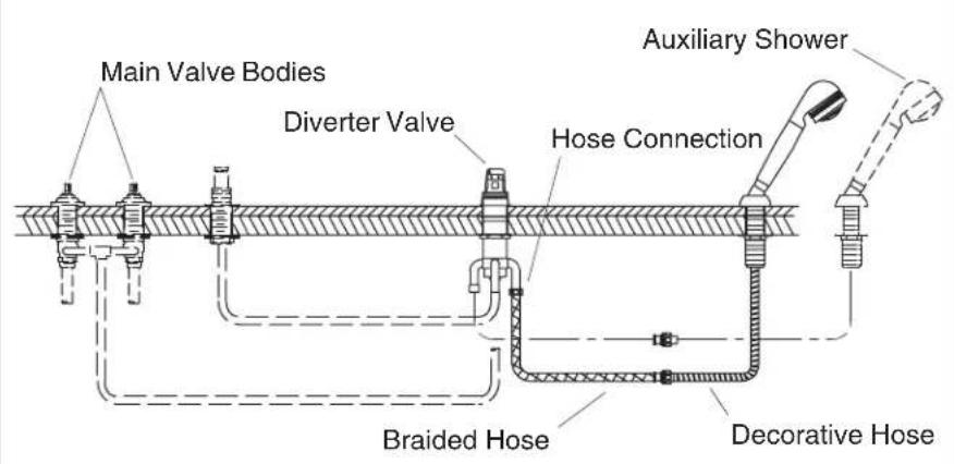
1. Component Layout
□ Verify the location of the components and the orientation of all ports.
☐ Determine the location and orientation of the transfer valve. The location of the bath spout, handshower, and the optional auxiliary shower will affect the piping and connectors needed.
□ Allow clearance for valve outlets, handles, bath spout, and handshower hoses.
2. Preparation
□ Provide an access panel for all installations.
□ Allow for access to the connection between the handshower and the handshower decorative base.
☐ For easiest installation, do not install the bath unit until all soldering (except supplies) is complete. Then install the bath and connect the supplies.
☐ Install the bath spout according to the spout installation instructions. If possible, do not install the finished trim until all other installations and construction are completed.
☐ Install the main valve bodies upstream from the diverter valve according to the valve body installation instructions.
□ Loosely secure the valve bodies.
Preparation (cont.)
☐ Follow the handle installation instructions to temporarily assemble the handles in order to adjust the valves to the proper height before connecting the lines to the transfer valve or supply.
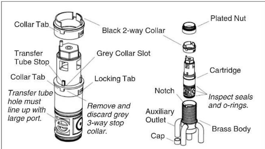
3. Convert to Two-Way Valve

CAUTION: Riskofpropertydamage.Foratwo-way configurationonly: the auxiliary outlet must be capped off to prevent possible leakage out of the unused auxiliary outlet, and the grey collar must be changed to the black two-way stop collar.
NOTE: The valve is pre-assembled for use as a three-way transfer valve.
□ Remove the plated nut.
□ Carefully pull the cartridge from the brass body.
NOTE: Use care to prevent the cartridge seals and O-rings from falling off, or becoming dirty or damaged.
☐ Line up the transfer tube stop with the slot in the grey collar.
☐ Use a flat-blade screwdriver to carefully pry the two locking tabs loose from the transfer tube.
□ Remove and discard the grey three-way stop collar.
☐ Verify the hole in the transfer tube lines up with the large port in the cartridge.
□ Align the black collar on the transfer tube with the collar tab lines on the large port of the cartridge.
☐ Snap the collar in place to ensure both locking tabs are fully engaged.
Convert to Two-Way Valve (cont.)
☐ Inspect the seals and O-rings for damage and proper fit. Make any adjustments if needed.
□ Carefully work the cartridge into the brass body until the collar tab fits into the notch in the brass body.
☐ Thread the plated nut onto the brass body and hand tighten.

4. Install the Transfer Valve

CAUTION: Riskofproductdamage. Excessive heat will damage the internal plastic components.
IMPORTANT! Do not apply excessive heat while soldering. Direct the torch flame away from the brass body.
IMPORTANT! Only apply direct heat to the connectors and extensions.
IMPORTANT! If there is limited access to the solder connections or if any other risk of excessive heat being applied to the brass body exists, remove the cartridge prior to soldering. If you remove the cartridge, protect the seals and O-rings from becoming dirty, being damaged, or misaligned.
☐ ForK-408: This valve can be installed to decks with a maximum thickness of no more than 1-7/16" (3.7 cm).
☐ ForK-409: This valve can be installed to decks with a maximum thickness of no more than 3-7/16"(8.7 cm).
☐ Ifinstallingtoafinisheddeck: At the transfer valve install location, drill a 2"(5 cm) hole.
IMPORTANT!! If the transfer valve is to be used in a two-way configuration, solder a cap to the auxiliary outlet.
□ Solder the inlet and outlet connectors and extensions.
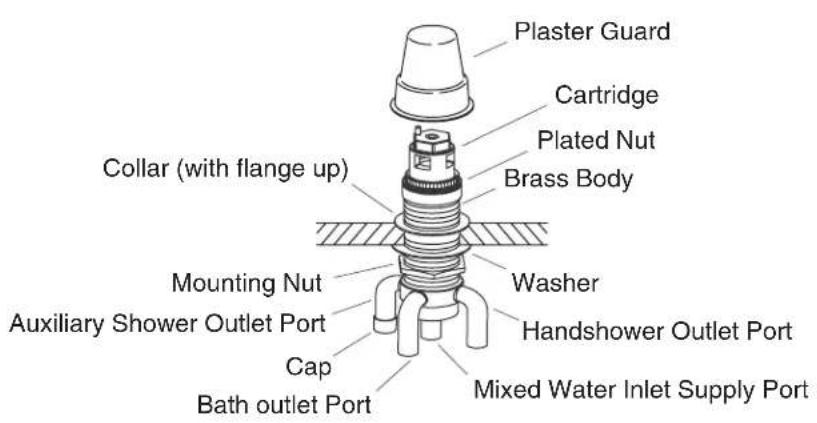
Install the Transfer Valve (cont.)
☐ Remove the plaster guard and plated nut from the valve. Do not remove the cartridge.
□ Remove the collar from the brass body.
☐ Thread the mounting nut down onto the brass body.
☐ Slide the washer onto the brass body until it is flush against the mounting nut.
☐ Slide the valve up through the deck/rim and thread the collar part way onto the brass body with the flange up.
☐ Hand tighten the plated nut onto the brass body.
□ Reinstall the plaster guard.
☐ Position the collar to create a gap 1/8"(3 mm) to 9/16"(1.4 cm) between the finished deck and the bottom of the plaster guard.
□ Securely tighten the mounting nut until it is flush against the finished deck.
□ Dry fit all the piping and connectors.
□ Solder the remaining piping and connectors.
5. Install the Handshower
☐ Install the hose guide and handshower according to the instructions packed with the product.
6. Complete the Valve Installation
□ Remove the plaster guard.
□ Turn on the main water supply.
□ Confirm proper operating of the transfer valve and associated fittings.
□ Carefully inspect the entire installation for leakage and proper operation. Adjustment as needed.
□ Hand tighten the plated nut to the brass body.
NOTE: If the trim will not be installed immediately, reinstall the plaster guard.
□ Install the trim according to the instructions packed with the product.
7. Installation Checkout
☐ Complete the installation of the valve, valve trim and any other components according to the instructions packed with the product.
□ Ensure all connections are tight.
□ Open the drain.
☐ Turn on the main water supply and check for leaks. Repair as needed.
Installation Checkout (cont.)
☐ Open both hot and cold valves and run water through the spout (if installed) to remove debris. Check for leaks.
□ Confirm proper diverter operation.
☐ Turn the cold and hot handles off and then on. Verify that the water flow is diverted back to the spout and that the handshower is off.
☐ Turn the valves to the closed position.