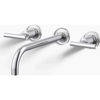
Triton K-8046 - Faucet KOHLER - Free user manual and instructions
Find the device manual for free Triton K-8046 KOHLER in PDF.


User questions about Triton K-8046 KOHLER
0 question about this device. Answer the ones you know or ask your own.
Ask a new question about this device
Download the instructions for your Faucet in PDF format for free! Find your manual Triton K-8046 - KOHLER and take your electronic device back in hand. On this page are published all the documents necessary for the use of your device. Triton K-8046 by KOHLER.
USER MANUAL Triton K-8046 KOHLER
M product numbers are for Mexico (i.e. K-12345M)
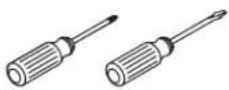
Assorted
Screwdrivers
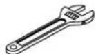
Adjustable Wrench
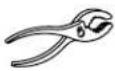
Pliers
Plus:
- Tubing Bender

Thread Sealant

Plumbers
Putty

Tube Cutter and Deburing Tool
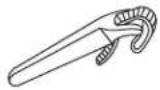
Strap Wrench
Thank You For Choosing Kohler Company
We appreciate your commitment to Kohler quality. Please take a few minutes to review this manual before you start installation. If you encounter any installation or performance problems, please don't hesitate to contact us. Our phone numbers and website are listed on the back cover. Thanks again for choosing Kohler Company.
Before You Begin
□ Shut off the main water supply.
□ Observe all local plumbing and building codes.
☐ If needed, complete the finished wall before beginning this installation.
☐ Kohler Co. reserves the right to make revisions in the design of faucets without notice, as specified in the Price Book.
text_image
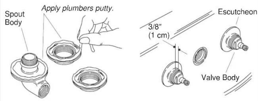
Spout Body Apply plumbers putty. 3/8" (1 cm) Escutcheon Valve Body1. Install the Valve Yoke
□ Apply a bead of plumbers putty or other sealant around the underside of the escutcheons and spout body according to the manufacturer's instructions.
Place the valve yoke through the lavatory and thread the escutcheons to the valve bodies. Leave about 3/8" (1 cm) of exposed threads in front of the escutcheons.
□ Remove any excess sealant.
text_image
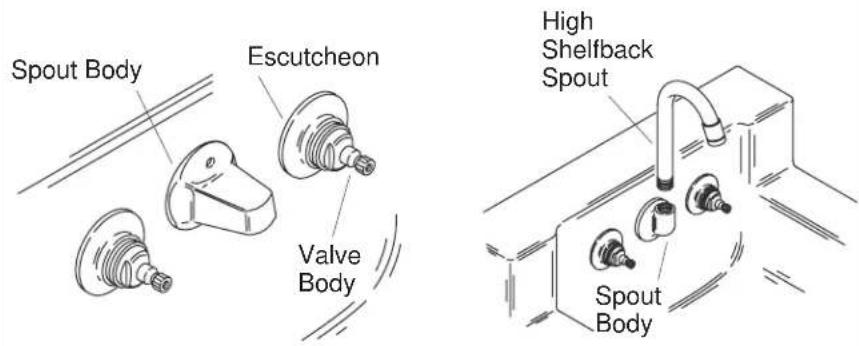
Spout Body Escutcheon Valve Body High Shelfback Spout Spout Body2. Install the Spout
IMPORTANT! Use care when installing the spout to avoid scratching the finish.
All Spouts
□ Apply thread sealant to the spout threads.
☐ Thread the spout body to the valve yoke with the spout body and valve escutcheons contacting the lavatory evenly.
□ Remove any excess putty or sealant.
High Shelfback Spout
□ Apply thread sealant to the spout threads.
☐ Thread the spout to the spout body. Use a clean strap wrench to tighten if necessary.
text_image
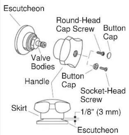
Escutcheon Round-Head Cap Screw Button Cap Valve Bodies Handle Button Cap Socket-Head Screw 1/8" (3 mm) Skirt Escutcheon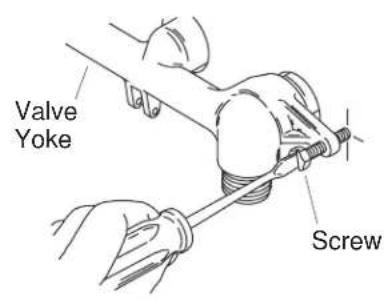
text_image
Valve Yoke Screw3. Install the Handles
NOTE: Illustration shows one of the available handle styles. All handle styles follow the steps below.
NOTE: Install lever handles so they are parallel to the floor (horizontal) when in the OFF position.
☐ Assemble the handles, screws, and button caps to the valve bodies.
☐ If either handle touches the escutcheon, adjust the escutcheon for a minimum 1/8" (3 mm) clearance between the handle skirt and escutcheon.
☐ Tighten the two screws on the valve yoke at the back of the lavatory to secure the valve body.
natural_image
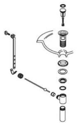
Exploded view diagram of a mechanical assembly with no visible text or symbolsStyle A Drain
natural_image
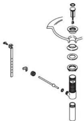
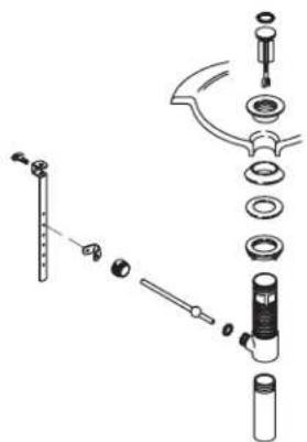
Exploded view diagram of a mechanical assembly with no visible text or symbolsStyle B Drain
4. Choose Drain Type
☐ Refer to the illustrations above to determine the drain style you received with your faucet.
□ Please follow the instructions for your drain style.
text_image
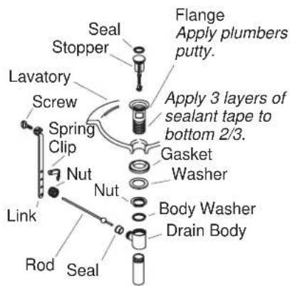
Flange Apply plumbers putty. Seal Stopper Lavatory Screw Spring Clip Nut Link Rod Seal Apply 3 layers of sealant tape to bottom 2/3. Gasket Washer Body Washer Drain Body5. Drain Installation-Style A
□ Remove the protective material from the flange.
- Wrap the bottom 2/3 of the flange threads with three layers of sealant tape.
□ Apply a ring of plumbers putty or other sealant to the underside of the flange according to the putty manufacturer's instructions.
☐ Insert the flange into the fixture drain hole.
☐ Assemble the gasket (tapered side up) and washer to the flange and partially thread the nut to the flange. Do not fully tighten the nut at this time.
☐ Install the body washer and drain body with the seal hole facing the back of the fixture and securely tighten the nut. Use care to avoid scratching the finish.
□ Remove any excess putty or sealant.
☐ Insert the stopper into the flange.
☐ Insert the seal into the seal hole on the body.
text_image
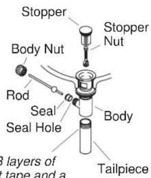
Stopper Body Nut Rod Seal Hole Slayers of tape and a Tailpiece Body Stopper Nut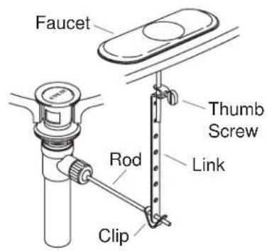
text_image
Faucet Thumb Screw Link Rod ClipApply 3 layers of sealant tape and a small bead of pipe sealant to threads.
6. Complete Drain Installation-Style A
☐ For regular installations, insert the short end of the rod into the body seal hole and under the stopper. For vandal-resistant installations, fit the rod through the hole in the stopper. Secure with the body nut.
☐ Remove and adjust the stopper so it lifts about 3/8" (1 cm) when opened. To adjust, loosen the stopper nut and shorten or lengthen the stopper as needed. Tighten the stopper nut.
□ Apply three layers of thread tape and a small bead of pipe sealant to the tailpiece threads.
☐ Thread the tailpiece to the body and tighten securely.
☐ Slide one end of the clip onto the rod. Slide the link onto the rod with the thumbscrew facing the back of the fixture.
□ Squeeze the other end of the clip, aligning the hole with the rod.
□ Move the link to the proper position by squeezing the clip and sliding it along the rod.
☐ Insert the lift rod into the hole in the faucet and then into the hole in the link.
☐ Tighten the thumbscrew onto the link so the lift rod knob extends above the lift rod hole.
text_image
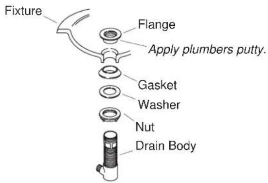
Fixture Flange Apply plumbers putty. Gasket Washer Nut Drain Body7. Drain Installation-Style B
□ Remove the protective cover from the flange.
□ Apply a ring of plumbers putty or other sealant to the underside of the flange according to the putty manufacturer's instructions.
☐ Assemble the nut, flat washer, and tapered gasket (tapered side up) fully onto the body.
□ From the underside of the fixture, insert the drain body up into the drain hole.
□ From the top of the fixture, securely hand tighten the flange onto the drain body.
☐ Make sure the drain body seal hole is facing the back of the fixture, and securely tighten the nut.
□ Remove any excess putty or sealant.
text_image
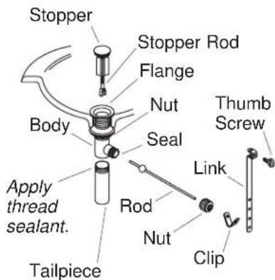
Stopper Flange Stopper Rod Nut Seal Body Apply thread sealant. Tailpiece Rod Nut Clip Link Thumb Screw8. Complete Drain Installation-Style B
□ Press the seal into the seal hole on the body.
☐ Insert the stopper into the flange.
☐ For regular installations, insert the short end of the rod into the body seal hole and under the stopper. For vandal-resistant installations, fit the rod through the hole in the stopper. Hand tighten the body nut.
☐ Remove and adjust the stopper as needed so it lifts about 3/8" (1 cm) when opened. To adjust, rotate the threaded stopper rod in or out as needed. Retighten the stopper nut.
□ Apply thread sealant tape to the tailpiece threads, and thread the tailpiece to the body. Tighten the tailpiece securely.
☐ Slide one end of the clip onto the rod. Slide the link onto the rod with the thumbscrew facing the back of the fixture.
☐ Squeeze the other end of the clip, aligning the hole with the rod. Move the link to the proper position by squeezing the clip and sliding it along the rod.
☐ Insert the lift rod into the hole in the faucet and then into the hole in the link.
☐ Tighten the thumbscrew onto the link so the lift rod knob extends 1/2" (1.3 cm) above the lift rod hole.
text_image
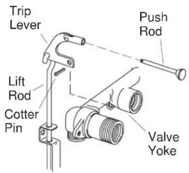
Trip Lever Lift Rod Cotter Pin Push Rod Valve Yoke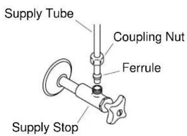
text_image
Supply Tube Coupling Nut Ferrule Supply Stop9. Install the Drain and Supplies
IMPORTANT! The drain steps apply to the K-8040 and K-8046 models only.
□ Install the drain according to the drain manufacturer's instructions.
☐ If necessary, connect the lift rod assembly.
☐ Cut the supply tubes, making sure there is enough length for the required penetration of the tubes into the supply-stops.
□ Debur all tubing cuts.
☐ Slip the coupling nuts onto the supply tubes.
□ Carefully position the round end of the supply tube (either flared end or ferrule) squarely into the valve body inlet.
□ Hand tighten the coupling nuts.
□ Carefully bend the supply tubes to align with the supply stops.
☐ Slide a coupling nut, then a ferrule, onto each supply tube.
☐ Insert the supply tubes into supply stop outlets, positioning the round ends of the ferrule squarely into the outlets.
□ Tighten all coupling nuts.
text_image
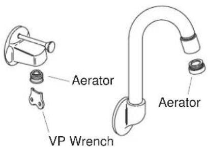
Aerator VP Wrench Aerator10. Complete the Installation
□ Ensure that all coupling nuts are tight. Repair as required.
☐ Ensure that both faucet handles are turned off (hot = counterclockwise to close, cold = clockwise to close).
□ Turn on the water supplies and check the installation for leaks.
□ Repair as needed.
□ Remove the aerator.
☐ Open the valves and run water through the spout for about a minute to remove any debris. Check for leaks.
□ Remove all debris from the aerator.
□ Turn the valves off, and reinstall the aerator.
text_image
Exploded view diagram of a mechanical assembly with labeled components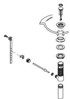
text_image
Exploded view diagram of a mechanical assembly with labeled parts including a thermometer, screwdriver, and valve componentsDrain de style BDrain de style A
natural_image
Exploded view diagram of a mechanical assembly with no visible text or symbolsEstilo de desagüe A
natural_image
Exploded view diagram of a mechanical assembly showing components like pressure gauge, screwdriver, and valve (no text or labels)Estilo de desagüe B