K-6805 - Faucet KOHLER - Free user manual and instructions
Find the device manual for free K-6805 KOHLER in PDF.


User questions about K-6805 KOHLER
0 question about this device. Answer the ones you know or ask your own.
Ask a new question about this device
Download the instructions for your Faucet in PDF format for free! Find your manual K-6805 - KOHLER and take your electronic device back in hand. On this page are published all the documents necessary for the use of your device. K-6805 by KOHLER.
USER MANUAL K-6805 KOHLER
Two-Handle Wall-Mount Valve and Handles
K-6805
natural_image
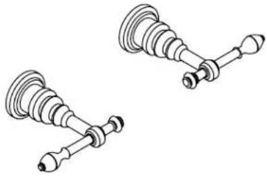
Technical line drawing of two mechanical components with no visible text or symbolsM product numbers are for Mexico (i.e. K-12345M)
Thank You For Choosing Kohler Company
We appreciate your commitment to Kohler quality. Please take a few minutes to review this manual before you start installation. If you encounter any installation or performance problems, please don't hesitate to contact us. Our phone numbers and website are listed on the back cover. Thanks again for choosing Kohler Company.
Tools and Materials
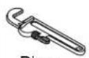
Pipe
Wrench
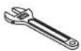
Adjustable Wrench
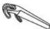
Strap Wrench
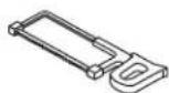
Hacksaw or Tubing Cutter
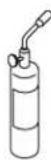
Propane Torch
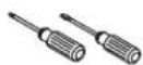
Assorted
Screwdrivers

Plumbers
Putty

Thread Sealant

Wrench

SolderHex
Before You Begin
□ Please read all instructions before you begin.
□ Observe all local plumbing and building codes.
□ Shut off the main water supply.
☐ Do not remove the plaster guards until instructed to.
☐ Before installation, unpack the components and inspect them for damage. Return the components to the carton until you are ready to install.
☐ Kohler Co. reserves the right to make revisions in the design of faucets without notice, as specified in the Price Book.
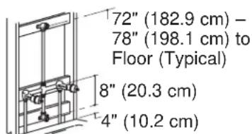
text_image
72" (182.9 cm) - 78" (198.1 cm) to Floor (Typical) 8" (20.3 cm) 4" (10.2 cm)Bath/Shower Installation
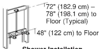
text_image
72" (182.9 cm) - 78" (198.1 cm) to Floor (Typical) 48" (122 cm) to Floor Shower InstallationShower Installation
text_image
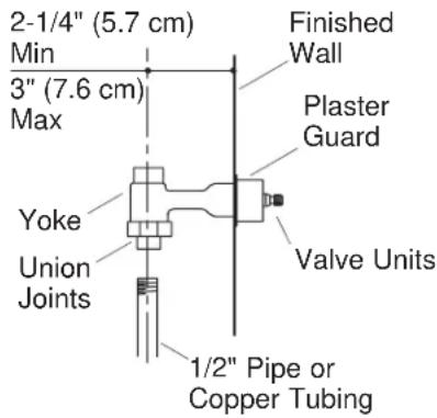
2-1/4" (5.7 cm) Min 3" (7.6 cm) Max Finished Wall Plaster Guard Valve Units Yoke Union Joints 1/2" Pipe or Copper Tubing1. Begin Installation - Floor Supplies

CAUTION: Risk of product damage. Remove the plaster guards, valve units, and aspirator before applying heat to the yoke.
□ Determine the location of the support framing for the yoke, spout, and the showerhead.
□ Install the support framing.
☐ The yoke has two union joints that can be used with either 1/2" pipe or copper tubing.
☐ Connect the hot and cold supplies to the union joints. They should be 2-1/4" (5.7 cm) minimum and 3" (7.6 cm) maximum from the finished wall.
☐ Reinstall the plaster guards, valve units, and aspirator that were removed before soldering.
text_image
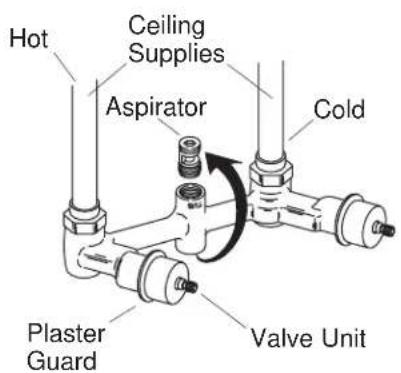
Hot Ceiling Supplies Aspirator Cold Plaster Guard Valve Unit2. Begin Installation - Ceiling Supplies
IMPORTANT! Perform these steps for ceiling installations only.
□ Remove the aspirator with a 3/8" hex wrench.
☐ Rotate the yoke 180^ so the supplies connect from the top of yoke.
NOTE: Rotating the yoke will reverse the direction that the lever handles close. For proper lever handle operation, reverse the valve units.
☐ Before removing the valve units, position them to the open position (cold = fully clockwise, hot = fully counterclockwise).
□ Remove the plaster guards.
□ Remove the valve units.
☐ Reinstall the valve units opposite their original locations (right to left, left to right).
□ Replace the plaster guards.
text_image
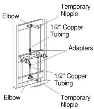
Elbow Temporary Nipple 1/2" Copper Tubing Adapters 1/2" Copper Tubing Elbow Temporary Nipple3. Complete the Valve Installation
NOTE: This section applies to all valve installation styles.

CAUTION: Risk of product damage. Remove the plaster guards, valve units, and aspirator before applying heat to the yoke.
IMPORTANT! Use thread sealant on all threaded connections.
□ Remove the plaster guards, valve units, and aspirator.
☐ Plumb using 1/2" copper tubing, elbows, and adapters.
□ Reinstall the plaster guards, valve units, and aspirator.
- Secure the bath and shower piping to the support framing and install temporary nipples.
☐ Install the provided plug in the appropriate valve body outlet if the installation is for bath or shower only.
☐ Close the valves (cold = counterclockwise, hot = clockwise).
□ Turn on the main water supply.
☐ Turn on the water to flush debris from valve and check for leaks.
□ Turn off water.
□ Complete the finished wall.
text_image
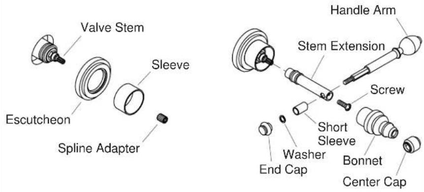
Valve Stem Sleeve Escutcheon Spline Adapter Handle Arm Stem Extension Screw Short Sleeve Washer End Cap Bonnet Center Cap4. Install the Lever Handles
□ Remove and discard the plaster guards from each valve stem.
☐ Slip an escutcheon and sleeve over each valve stem and against the finished wall.
□ Install a spline adapter onto each valve stem.
☐ Install a stem extension onto each spline adapter so the handle holes are facing each side.
☐ Install the stem extension to each valve stem with a screw (provided).
☐ Slip a bonnet over each stem extension and thread onto each valve until the escutcheon, sleeve, and bonnet are snug against the finished wall.
☐ Slip a center cap onto each bonnet so the two side holes on each cap align with the two holes on each bonnet.
☐ The lever handles are shipped fully assembled. Remove the end cap, plastic washer, and short sleeve from each handle.
☐ Slip a lever handle through the two holes on each center cap.
☐ Reinstall each short sleeve so the curved end fits snugly onto the lever handle arm.
☐ Reinstall a plastic washer and tighten an end cap onto the threaded end of each lever handle.
text_image
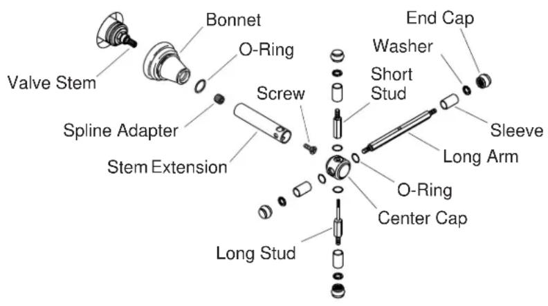
Valve Stem Spline Adapter Stem Extension Bonnet O-Ring Screw End Cap Washer Short Stud Long Arm Sleeve O-Ring Center Cap Long Stud5. Install the Cross Lever Handles
□ Remove and discard the plaster guards from each valve stem.
□ Install a spline adapter onto each valve stem.
☐ Install a stem extension onto each spline adapter so the holes in the extension are at the top, bottom and each side.
☐ Secure the stem extension to each valve stem with a screw (provided).
☐ Slip a bonnet and O-ring over each stem extension. Thread a bonnet onto each valve until snug against the finished wall.
☐ Fit a center cap onto each stem extension so the same-sized holes in each piece align.
☐ All handle arms are shipped fully assembled. The long arms have a center hole. Remove an end cap, washer, and sleeve from each long arm.
☐ Insert a long arm into the large hole of each center cap.
☐ Reinstall the sleeve, washer, and end cap onto each long arm and tighten.
☐ Disassemble the two remaining handle arms by loosening the short stud from the long stud of each arm. Be certain to separate the two O-rings at the center of the handle arm so one remains with each stud.
☐ Insert the longer end of each long stud through the holes of each center cap.
Install the Cross Lever Handles (cont.)
☐ Install another O-ring onto the spindle end that protrudes through each center cap. Thread the female end of each short stud onto each protruding spindle end and tighten.
6. Complete the Installation
□ Make sure all the connections are tight.
□ Open the drain.
☐ Turn on the main water supply and check for leaks.
☐ Open the hot and cold valves and check for leaks.
□ Run the water for about a minute and turn off.