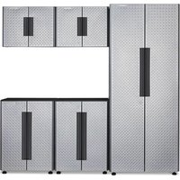
GAGB54SBJW - Storage bench Gladiator - Free user manual and instructions
Find the device manual for free GAGB54SBJW Gladiator in PDF.

User questions about GAGB54SBJW Gladiator
0 question about this device. Answer the ones you know or ask your own.
Ask a new question about this device
Download the instructions for your Storage bench in PDF format for free! Find your manual GAGB54SBJW - Gladiator and take your electronic device back in hand. On this page are published all the documents necessary for the use of your device. GAGB54SBJW by Gladiator.
USER MANUAL GAGB54SBJW Gladiator
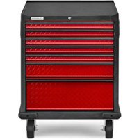
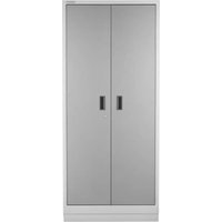
GAGB54SBJG - Hammered Granite/Silver
GAGB54SBJW - Hammered White/Gray Slate
GAGB54SBJSG - Hammered Granite/Granite Slate
Modèle
ASSEMBLY INSTRUCTIONS 4
Storage/Shoe Bench
Use Requirements 4
Storage/Shoe Bench Parts 4
Tools and Parts 4
Attach Back Panels
Attach the Bottom Panel
Assemble Shelves (Optional) 5
Install Doors (Optional) 5
Registering Your Product
WARRANTY 6
SECURITE DU BANC DE RANGEMENT/
POUR CHAUSSURES 7
PIECES DU BANC DE RANGEMENT/
POUR CHAUSSURES 8
INSTRUCTIONS D'ASSEMBLAGE. 9
Your safety and the safety of others are very important.
We have provided many important safety messages in this manual and on your appliance. Always read and obey all safety messages.

This is the safety alert symbol.
This symbol alerts you to potential hazards that can kill or hurt you and others.
All safety messages will follow the safety alert symbol and either the word "DANGER" or "WARNING."
These words mean:
DANGER
WARNING
You can be killed or seriously injured if you don't immediately follow instructions.
You can be killed or seriously injured if you don't follow instructions.
All safety messages will tell you what the potential hazard is, tell you how to reduce the chance of injury, and tell you what can happen if the instructions are not followed.
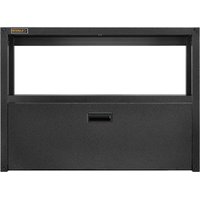
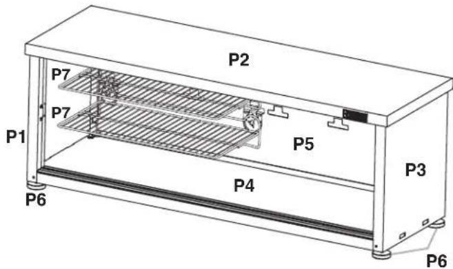
STORAGE/SHOE BENCH PARTS
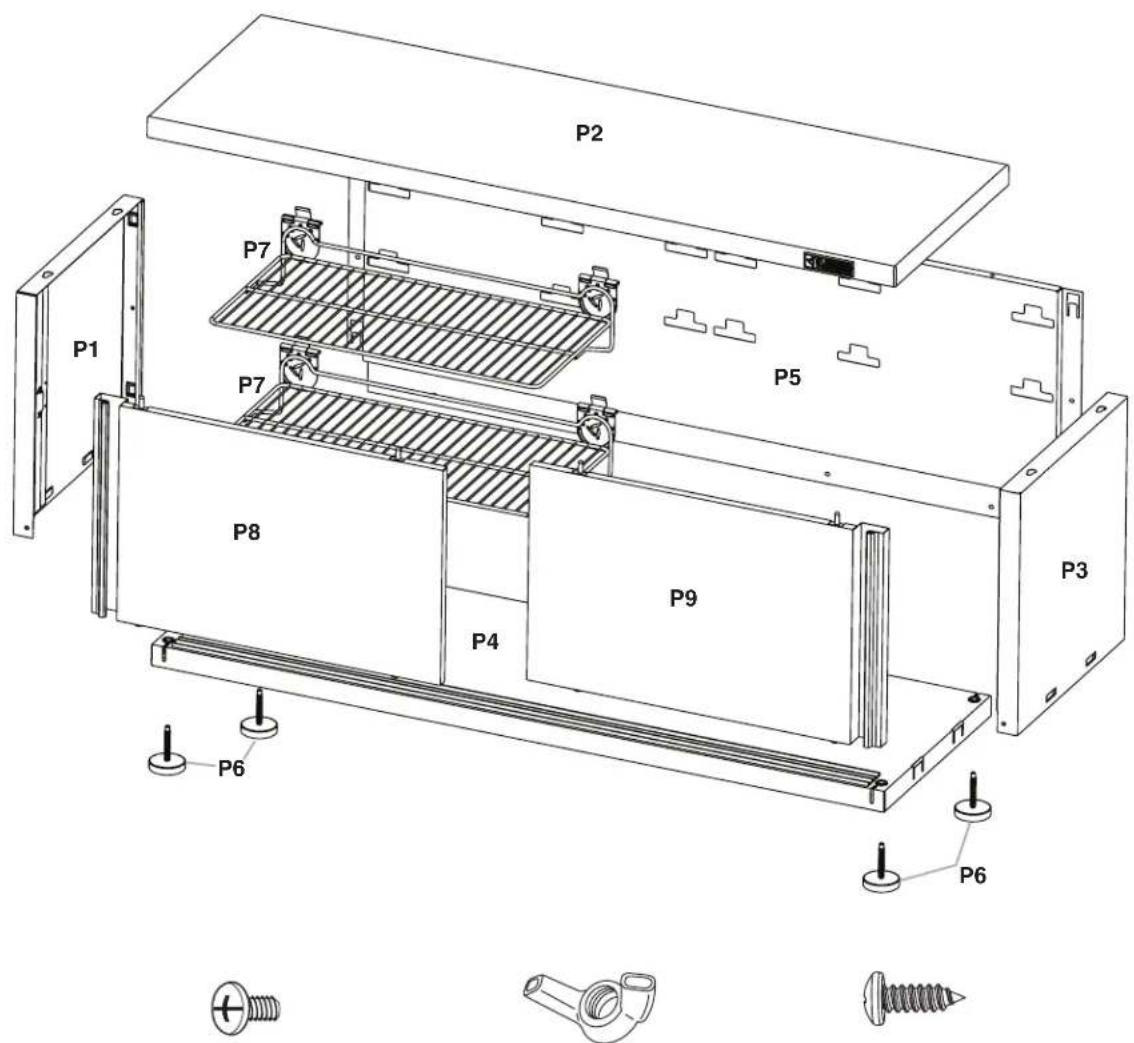
F1. 10-24 x 1/4" long Phillips-head Screw
F2. 10-24 Wing nut
F3. 8 x 1/2" long Phillips-head screw
| Label Nomenclature Qty. | ||
| P1 | Left Side Panel 1 | |
| P2 | Hardwood Top 1 | |
| P3 | Right Side Panel 1 | |
| P4 | Bottom Panel 1 | |
| P5 | Back Panel 1 | |
| P6 | Leveler Feet 4 | |
| P7 | 24" Shelf (Optional) 2 | |
| P8 | Left Hand Door (Optional) 1 | |
| P9 | Right Hand Door (Optional) 1 | |
| F1 | #10-24 x 1/4" long Phillips-head Screw 6 | |
| F2 | #10-24 Wing Nut 4 | |
| F3 | #8 x 1/2" long Phillips-head Screw | 4 |
ASSEMBLY INSTRUCTIONS
Storage/Shoe Bench Use Requirements
■Intended for use in a garage.
Maximum weight limit is 35 lbs (15.9kg) for each shelf.
Maximum weight limit is 500 lbs (227kg) for the hardwood storage/shoe bench.
Storage/Shoe Bench Parts
- Remove and verify the contents. Contents include the parts and fasteners shown in "Parts."
- Dispose of/recycle all packaging materials.
Tools and Parts
Gather the required tools before starting installation.
Tools Needed:
1/2" wrench
Phillips-head screwdriver
Level
WARNING
Excessive Weight Hazard
Use two or more people to move, assemble or install cabinet.
Failure to do so can result in back or other injury.
IMPORTANT:
Two people may be required to complete the assembly.
The hardwood top (P2) is intentionally designed so that the heads of the lag bolts which were pre-assembled on the hardwood top (P2) will match with the key holes on the side panel (P3 and P1) only when it is positioned correctly. If the bolt heads on the hardwood top (P2) do not match with the key holes on the side panel (P3 and P1), turn the hardwood top (P2) around.
1. Place the hardwood top (P2) on floor (upside down, with the protruding lag bolt heads pointing upward).
2. Assemble the left side panel (P1). Place the panel perpendicular to workbench top, making sure to align the key holes in the panel with the pre-assembled lag bolts in the top.
3. Use a wrench to tighten the two lag bolts [which were pre-assembled onto the hardwood top (P2)]. Fully tighten the bolts.
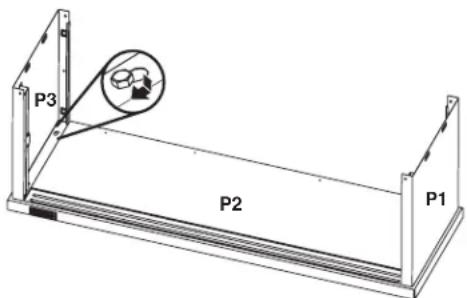
- Repeat above steps 2 and 3 for the other cabinet side.
Attach Back Panels

F1.
10-24 x 1/4"
long Phillips-head Screw (2)
F3.
8 × 1 / 2
long Phillips-head screw (4)
- Slide in the back panel (P5) so that the tabs in the back panel are aligned with the slots of the side panels. There are two tabs on each side of the panel (See detail to illustration below).
- Push in and ensure the four tabs are fully engaged in the slots.
- Attach the four # 8× 1 / 2 long Phillips-head screws (F3) to the hardwood top (P2).
- Attach the two #10-24 x 1/4" long Phillips-head screws (F1) between the side panels (P3 and P1) and back panel (P5). Do not fully tighten the screws. This will be done later.
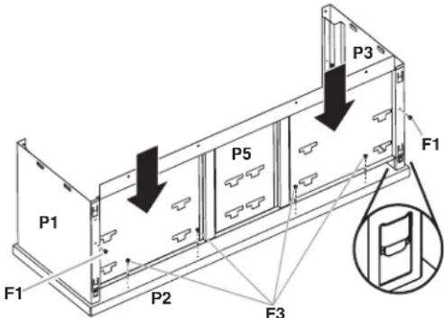
F1. 10-24 x 1/4" long Phillips-head screw (2)
F3. 8 × 1/2 long Phillips-head screw (4)
Attach the Bottom Panel

F1. 10-24 x 1/4" long Phillips-head Screw (4)
F2. 10-24 wing nut (4)
- Place the bottom panel (upside down so the mating edges are pointing up), and make sure that the four tabs and slots are fully engaged.
- Attach the #10-24 x 1/4" long Phillips-head screws (F1) between the back panel (P5) and the bottom panel (P4). Do
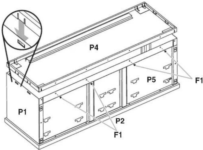
not fully tighten the Phillips-head screws.
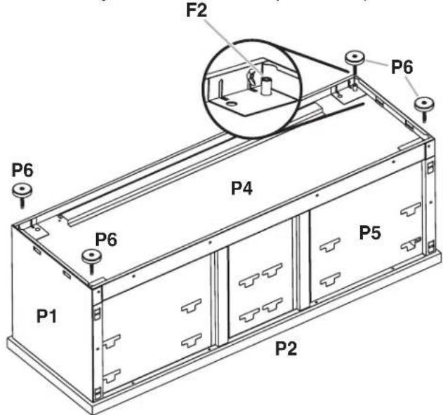
- Install and tighten the four #10-24 wing nuts (F2) (hand tight) onto the protruding screw threads (included on the bottom panel) at each of the four corners.
- Install the leveler feet (P6) to the bottom panel (P4).
- Tighten all #10-24 x 1/4" long Phillips-head screws (F1) and all remaining loose screws from the previous steps.
Assemble Shelves (Optional)
WARNING
Excessive Weight Hazard
Use two or more people to move, assemble or install cabinet.
Failure to do so can result in back or other injury.
Use two or more people to turn the storage/shoe bench over to an upright position. Install the shelf (P7) at the desired location. Insert both tabs fully into the slots at an angle, and then straighten shelf to fully engage the slots in the tabs.
Install Doors (Optional)
- Assemble the right-hand door (P9) first, as you face the front of the storage/shoe bench.
- Engage the door top with the rail by placing the two top pins into the guides, and then push the pins in (collapse) against the rail.
- Swing the door bottom down and push in to make the rollers engage into the bottom rail. Slide the door back and forth several times to ensure the door is engaged completely.
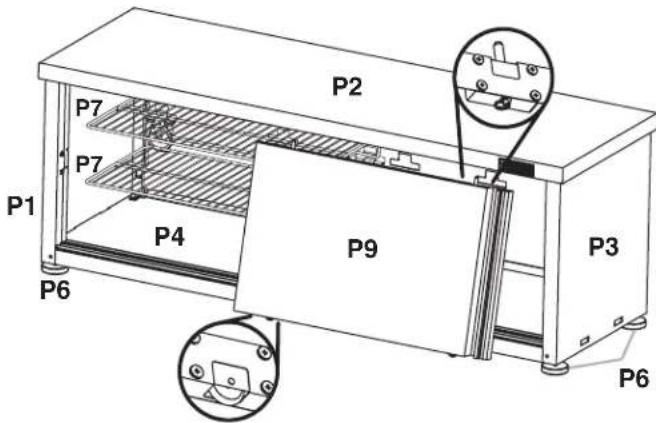
- Repeat steps 2 and 3 to assemble the left hand door (P8).
REGISTERING YOUR PRODUCT
There are many benefits to registering your product. Find out more and register your product online at: www.gladiatorgarageworks.com Consumers in Canada can call 1-800-807-6777.
In the U.S.A. call 1-866-342-4089.
WARRANTY
For warranty information:
In the U.S.A. call 1-866-342-4089 or visit our website at
www.gladiatorgarageworks.com
In Canada call 1-800-807-6777 or visit our website at
www.gladiatorgarageworks.ca
SECURITE DU BANC DE RANGEMENT/POUR CHAUSSURES
www.gladiatorgarageworks.com.
www.gladiatorgarageworks.com
www.gladiatorgarageworks.ca
SEGURIDAD DEL BANCO PARA ALMACENAMIENTO/CALZADO
www.gladiatorgarageworks.com.
www.gladiatorgarageworks.com
www.gladiatorgarageworks.ca