Flex Cabinet System IV GANF05WFMTS - Storage system Gladiator - Free user manual and instructions
Find the device manual for free Flex Cabinet System IV GANF05WFMTS Gladiator in PDF.

User questions about Flex Cabinet System IV GANF05WFMTS Gladiator
0 question about this device. Answer the ones you know or ask your own.
Ask a new question about this device
Download the instructions for your Storage system in PDF format for free! Find your manual Flex Cabinet System IV GANF05WFMTS - Gladiator and take your electronic device back in hand. On this page are published all the documents necessary for the use of your device. Flex Cabinet System IV GANF05WFMTS by Gladiator.
USER MANUAL Flex Cabinet System IV GANF05WFMTS Gladiator
GANF03WFMTS - Hammered Granite / Tread Full Door Silver GANF03WDMTS - Hammered Granite / Tread Full Door Silver GANF04WFMTS - Hammered Granite / Tread Full Door Silver GANF05WFMTS - Hammered Granite / Tread Full Door Silver GANF04WCMTS - Hammered Granite / Tread Full Door Silver
Modèle:
Assembly Instructions
natural_image
Isometric line drawing of three server rack units with mesh patterns, no text or symbols presentTABLE OF CONTENTS/TABLE DES MATIÈRES/TABLA DE CONTENIDOS
CABINET SAFETY......2
FLEX CABINET SYSTEMS ....3
HARDWARE AND PARTS......4
ASSEMBLY INSTRUCTIONS......5
INSTALL CABINET TO
CARE AND CLEANING....20
FLEX ACCESSORIES....20
WARRANTY....20
SÉCURITÉ DE L'ARMOIRE .....21
SYSTÈME D'ARMOIRES FLEX .....22
QUINCAILLERIE ET PIÈCES......23
INSTRUCTIONS
D'ASSEMBLAGE....24
INSTALLER L'ARMOIRE SUR
LES PROFILÉS GEARTRACK®
GLADIATOR ^® 31
INSTALLER L'ARMOIRE AUX
PANNEAUX GEARWALL®
GLADIATOR ^® 35
RÉGLAGE DE LA PORTE .....37
RETRAIT ET RÉINSTALLATION
DU TIROIR....37
CAPACITÉ DE CHARGE ....38
ENTRETIEN....39
SOINS ET NETTOYAGE....39
ACCESSOIRES FLEX....39
GARANTIE....39
SEGURIDAD DEL GABINETE......40
SISTEMAS DE GABINETE FLEX......41
TORNILLERÍA Y PIEZAS......42
INSTRUCCIONES DE
ENSAMBLAJE......43
INSTALE EL GABINETE EN
EL CANAL GLADIATOR®
GEARTRACK ^® 50
INSTALE EL GABINETE EN EL
PANEL GLADIATOR® GEARWALL®
54
Your safety and the safety of others are very important.
We have provided many important safety messages in this manual and on your product. Always read and obey all safety messages.

This is the safety alert symbol.
This symbol alerts you to potential hazards that can kill or hurt you and others.
All safety messages will follow the safety alert symbol and either the word "DANGER" or "WARNING."
These words mean:
DANGER
You can be killed or seriously injured if you don't immediately follow instructions.
WARNING
You can be killed or seriously injured if you don't follow instructions.
All safety messages will tell you what the potential hazard is, tell you how to reduce the chance of injury, and tell you what can happen if the instructions are not followed.
To reduce the risk of serious injury, read and follow the safety instructions below before assembling and using this product.
This product is intended for use in the garage.
WARNING
Excessive Weight Hazard
Use two or more people to move and install cabinet.
Failure to do so can result in back or other injury.
WARNING

Tip Over Hazard
A child or adult can tip the cabinet and be killed.
Firmly close and lock doors and drawers before moving the cabinet.
Failure to do so can result in serious injury or death.
IMPORTANT SAFETY INSTRUCTIONS
■ The product is intended for use in the garage.
■ Close and lock the doors and drawer before moving this product.
■ It is always recommended to secure the cabinets to the wall with the wall strap and bracket provided.
■ DO NOT put anything on the top panel of the wall cabinet or tall cabinet.
If the base cabinets have casters attached, please remove all items from the cabinet tops before moving the base cabinets.
SAVE THESE INSTRUCTIONS
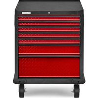
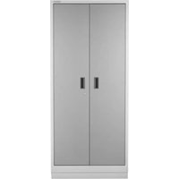
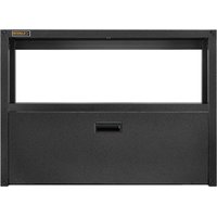
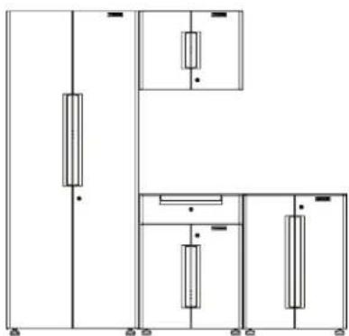
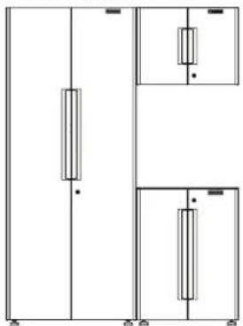
GLADIATOR® FLEX CABINET SYSTEMS
CABINETS
natural_image
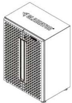
Isometric line drawing of a rectangular electronic device with a grid-patterned panel and central vertical slot (no text or symbols)24" Wall Cabinet
natural_image
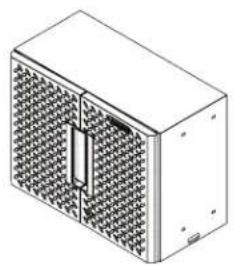
Isometric illustration of a rectangular device with a mesh panel and a vertical slot, no text or symbols present.24" 2-Door Base Cabinet
natural_image
Isometric line drawing of a rectangular electronic device with a grid-patterned front panel and control panel (no text or symbols)24" 1-Drawer 2-Door Base Cabinet
natural_image
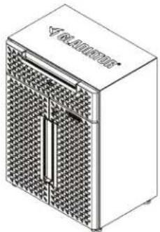
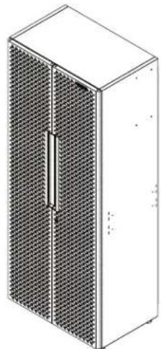
Isometric line drawing of a server rack cabinet with mesh panels (no text or symbols)30" Tall Cabinet
SUITES

natural_image
Pure electrical circuit lines without any symbolsSKU: GANF03WFMTS
| Cabinets Included | |
| Description Quantity | |
| 30" Tall Cabinet 1 | |
| 24" Wall Cabinet 1 | |
| 24" 2-Door Base Cabinet | 1 |
natural_image
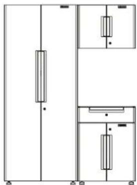
Pure electrical circuit lines without any symbolsSKU: GANF03WDMTS
| Cabinets Included | |
| Description Quantity | |
| 30" Tall Cabinet 1 | |
| 24" Wall Cabinet 1 | |
| 24" 1-Drawer2-Door Base Cabinet | 1 |
natural_image
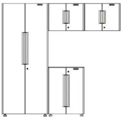
Pure electrical circuit lines without any symbolsSKU: GANF04WFMTS
| Cabinets Included | |
| Description Quantity | |
| 30" Tall Cabinet 1 | |
| 24" Wall Cabinet 2 | |
| 24" 2-Door Base Cabinet | 1 |
natural_image
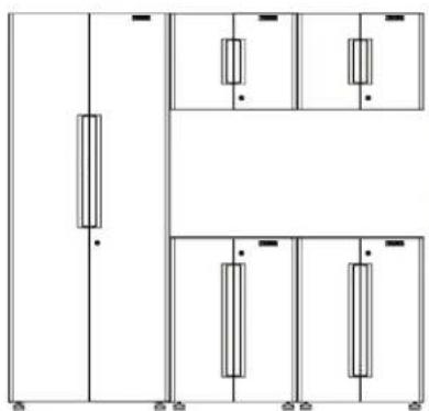
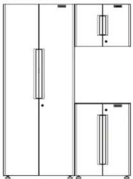
Pure electrical circuit lines without any symbolsSKU: GANF05WFMTS
| Cabinets Included | |
| Description Quantity | |
| 30" Tall Cabinet 1 | |
| 24" Wall Cabinet 2 | |
| 24" 2-Door Base Cabinet | 2 |
natural_image
Pure electrical circuit lines without any symbolsSKU: GANF04WCMTS
| Cabinets Included | |
| Description Quantity | |
| 30" Tall Cabinet 1 | |
| 24" Wall Cabinet 1 | |
| 24" 2-Door Base Cabinet | 1 |
| 24" 1-Drawer 2-Door Base Cabinet | 1 |
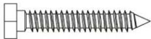
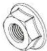
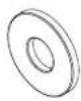
HARDWARE AND PARTS
NOTE: Hardware not shown to actual size. All hardware is packed in the hardware box, including the closet rod.

F4F1P1F3
F2
F5
P2P4
P3
P5
natural_image
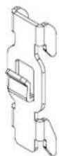
Technical line drawing of a rectangular panel with internal slots and mounting holes (no text or symbols)P6
text_image
VACLATORP7P8P9
natural_image
Isometric wireframe view of a rectangular metal tray with grid pattern (no text or symbols)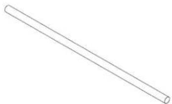
natural_image
Simple line drawing of a straight cylindrical rod (no text or symbols)
natural_image
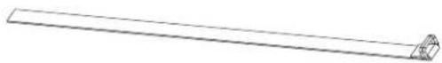
Pure technical line drawing of a rectangular metal beam with two end fasteners (no text or symbols)P10P11
natural_image
Simple line drawing of a rectangular block (no text or symbols)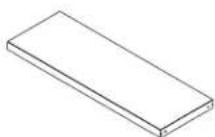
P12P13

P14
| No. | Description |
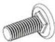
| F1 M6 | x 16 hex socket head screw |
| F2 M6 | x 40 hex tapping bolt |
| F3 M6 | flange nut |
| F4 Washer | |
| F5 M6 | round head square neck bolt |
| P1 Wall strap | |
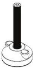
| P2 Adjustable foot | |
| P3 Shelf support | |
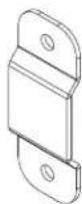
| P4 Wall bracket | |
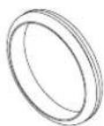
| P5 Grommet | |
| P6 Mounting bracket | |
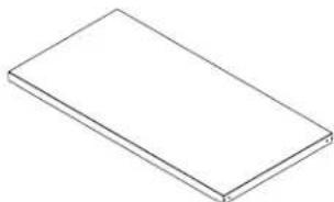
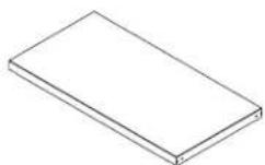
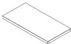
| P7 Top mat for base cabinet | |
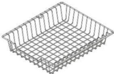
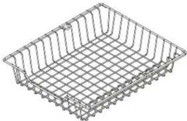
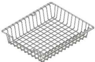
| P8 Basket | |
| P9 Closet rod for tall cabinet | |
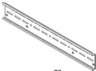
| P10 Basket track | |
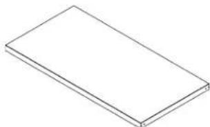
| P11 Shelf for tall cabinet | |
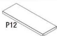
| P12 Shelf for wall cabinet | |
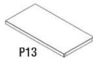
| P13 Shelf for base cabinet | |
| P14 Key | |
ASSEMBLY INSTRUCTIONS
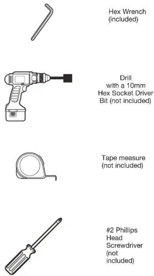
Tools Required
■ Gather the required tools and parts before starting installation.
- Read and follow the instructions included with the required tools.
Tools Needed:
1. Install the Adjustable Feet
■Close and lock the cabinet doors.
NOTE: If you need to open the cabinet doors during adjustable feet assembly open them slowly and do not put any weight on the open doors. This avoids damage to the hinges.
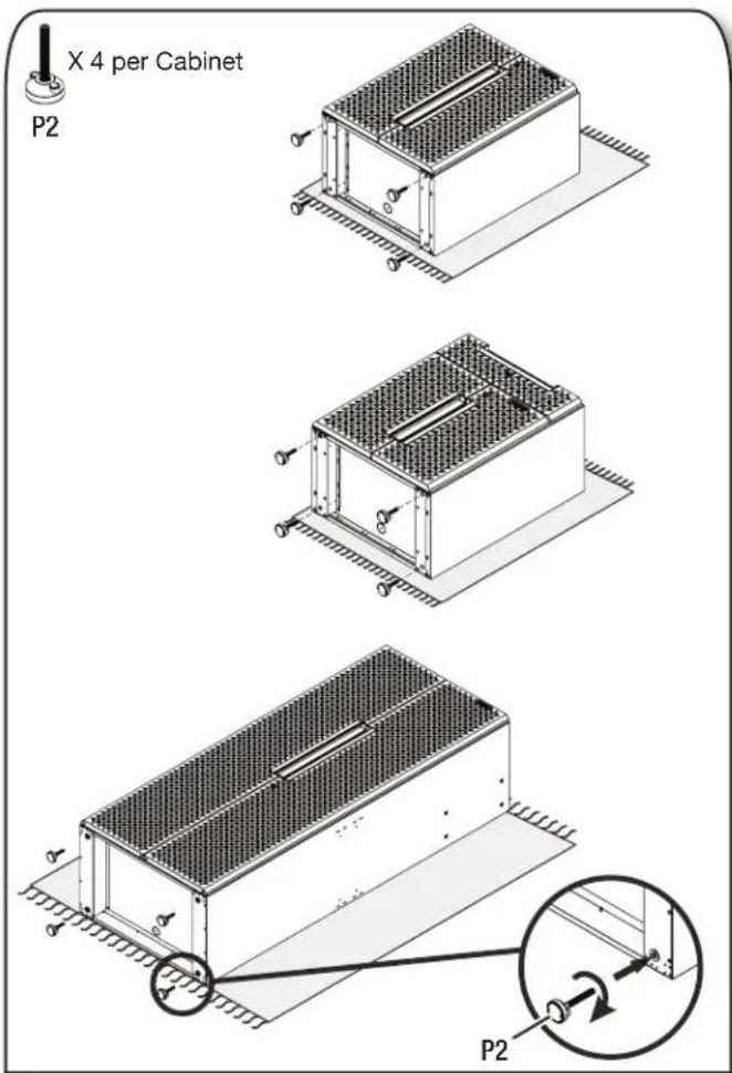
■Two people may be required to complete the assembly. Place the cardboard sheet packaging provided on the ground and lay the cabinets flat on its back (doors facing up).
■Install 4 adjustable feet to the bottom of each base cabinet and tall cabinet as shown
ASSEMBLY INSTRUCTIONS
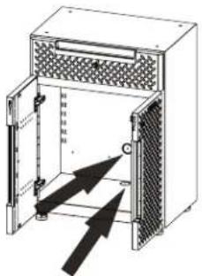
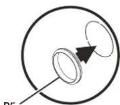
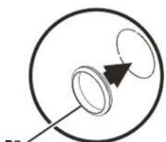
2. Install the Grommets for Cord Management (Optional)

X 1 per Cabinet
P5
text_image
Technical diagram of a device with labeled components and directional arrows indicating flow or movement.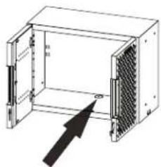
natural_image
Diagram of an electronic device enclosure with internal components and a black arrow pointing to a component (no text or symbols present)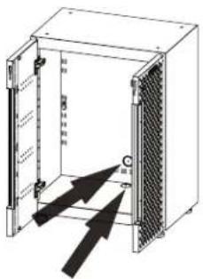
text_image
Technical diagram of an electrical enclosure with labeled components and directional arrows indicating movement or flow.
natural_image
Simple line drawing of a circular object with a pointer and arrow, no text or symbols present.1

natural_image
Simple line drawing of a circular object with an arrow pointing to it, no text or symbols present.2
natural_image
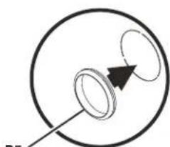
Simple diagram showing two concentric circles with a black arrow pointing to one circle, labeled 'P5' at the bottom left (no text or symbols within the circles)3

natural_image
Simple circular ring shape with a black inner ring, no text or symbols present.4
After Installation
■Use the short side of the hex wrench to punch out the knock-outs of your desired cord access holes.
■Then install the grommets into those holes.
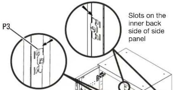
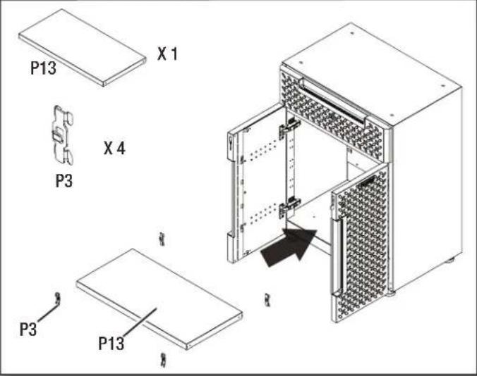
3. Install the Shelves
■ Insert shelf brackets into the slots at the desired heights and place the shelves over the shelf brackets.
■Make sure all four shelf brackets are installed at the same height.
3a. Install the shelf in the 2-door base cabinet.
X1X4

P3
text_image
P3 Slots on the inner back side of side panelSlots on the inner front side of side panel

text_image
P13Shelf locked by shelf bracket after installation
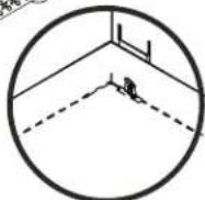
3b. Install the shelf in the wall cabinet.
X1

P3
X4
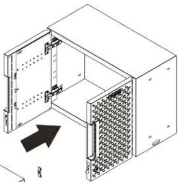
natural_image
Isometric line drawing of an open industrial rack unit with internal components and a black arrow indicating direction (no text or symbols)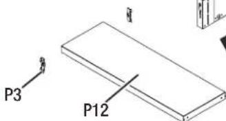
text_image
P3 P12[Unreadable]
ASSEMBLY INSTRUCTIONS
3c. Install the shelf in the 1-drawer 2-door base cabinet.
text_image
P13 X 1 P3 X 4 P3 P133d. Install the shelves in the tall cabinet.
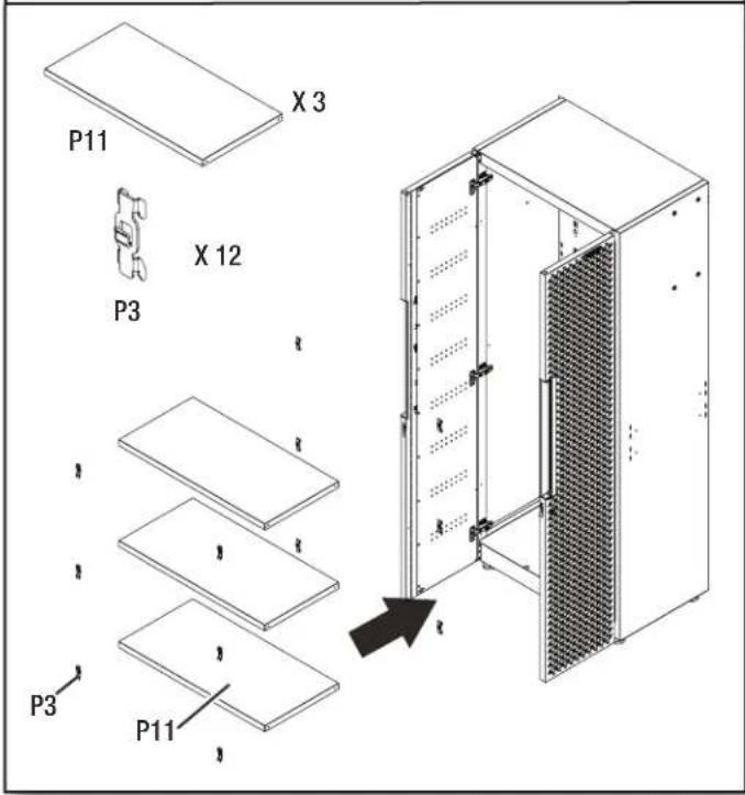
text_image
P11 X 3 X 12 P3 P3 P114. Connect the Tall Cabinet to the Wall
NOTE: This instruction is for attaching the cabinets directly to the wall. For attaching the cabinets to Gladiator® GearTrack® Channels, please refer to page 12.
IMPORTANT: The M6 x 40 hex tapping bolts should be drilled into a wall stud.
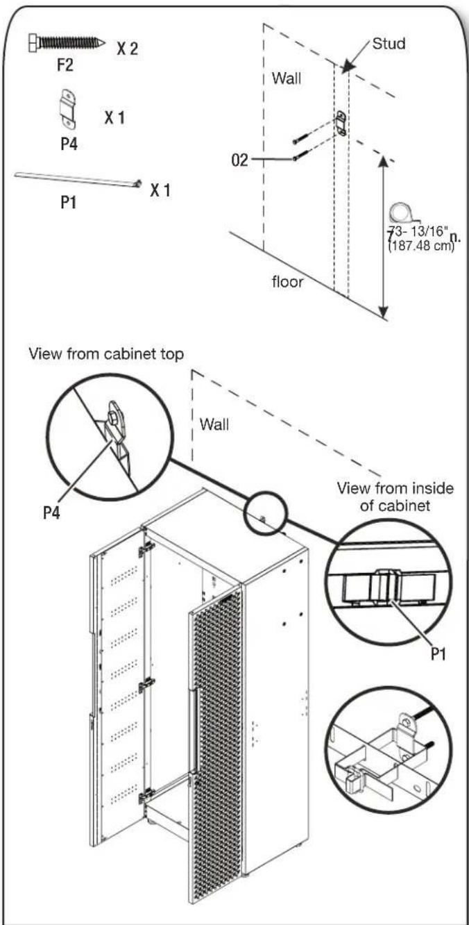
text_image
F2 X 2 P4 X 1 P1 X 1 Wall 02 Stud floor 73-13/16" (187.48 cm) View from cabinet top P4 Wall View from inside of cabinet P1■Bolt the wall bracket with two M6 x 40 hex tapping bolts (F2) to a wall stud. Fasten the tall cabinet by using the wall strap to tie the tall cabinet and wall bracket together.
ASSEMBLY INSTRUCTIONS
5. Connect the Wall Cabinet(s) to the Wall
NOTE: This instruction is for attaching the wall cabinet directly to the wall. For attaching the wall cabinet to Gladiator® GearTrack® channels, please refer to page 12.
IMPORTANT: The M6 x 40 hex tapping bolts should be drilled into a wall stud.
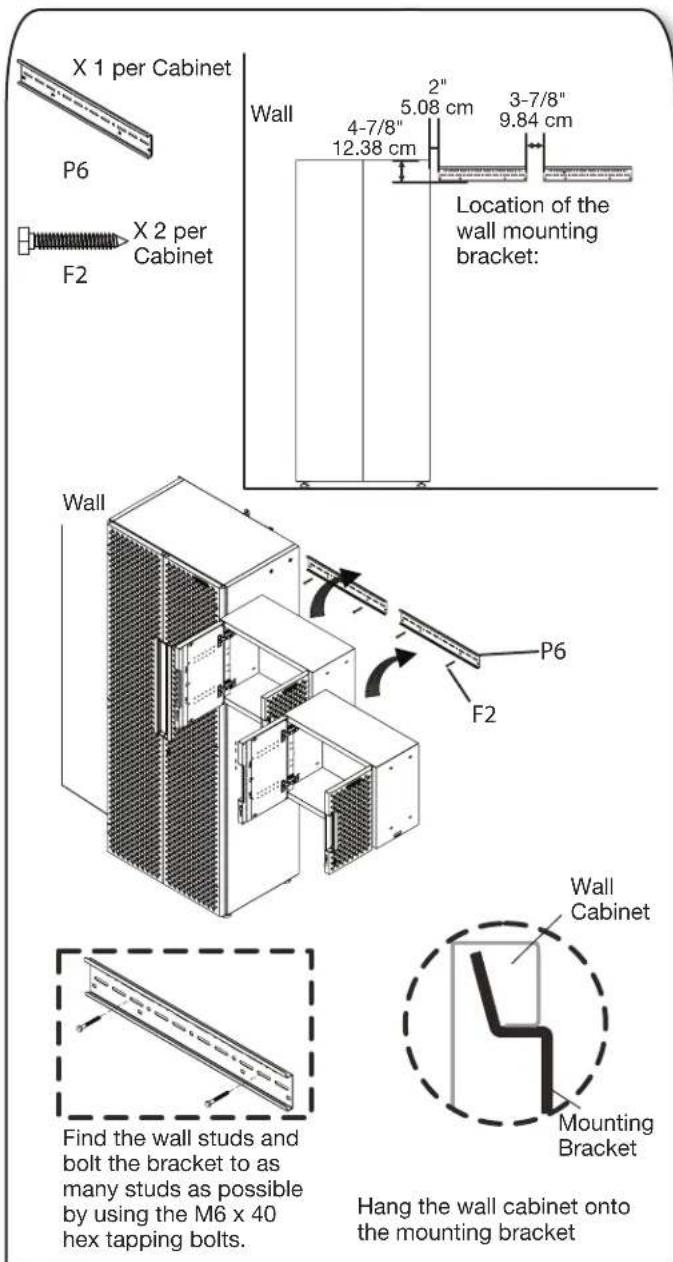
text_image
X 1 per Cabinet P6 F2 X 2 per Cabinet Wall 4-7/8" 12.38 cm 2" 5.08 cm 3-7/8" 9.84 cm Location of the wall mounting bracket: Wall P6 F2 Find the wall studs and bolt the bracket to as many studs as possible by using the M6 x 40 hex tapping bolts. Hang the wall cabinet onto the mounting bracket Wall Cabinet Mounting Bracket■The distance between the locker's top and bracket's bottom edge should be 4-7/8".
■The distance between the locker and bracket should be 2".
■The distance between brackets should be 3-7/8".
6. Connect the Wall Cabinet(s) to the Adjoining Cabinets
IMPORTANT: The M6 x 40 hex tapping bolts should be drilled into a wall stud.
NOTE: This is an example to show you how to build your system by connecting multiple cabinets (sold separately).
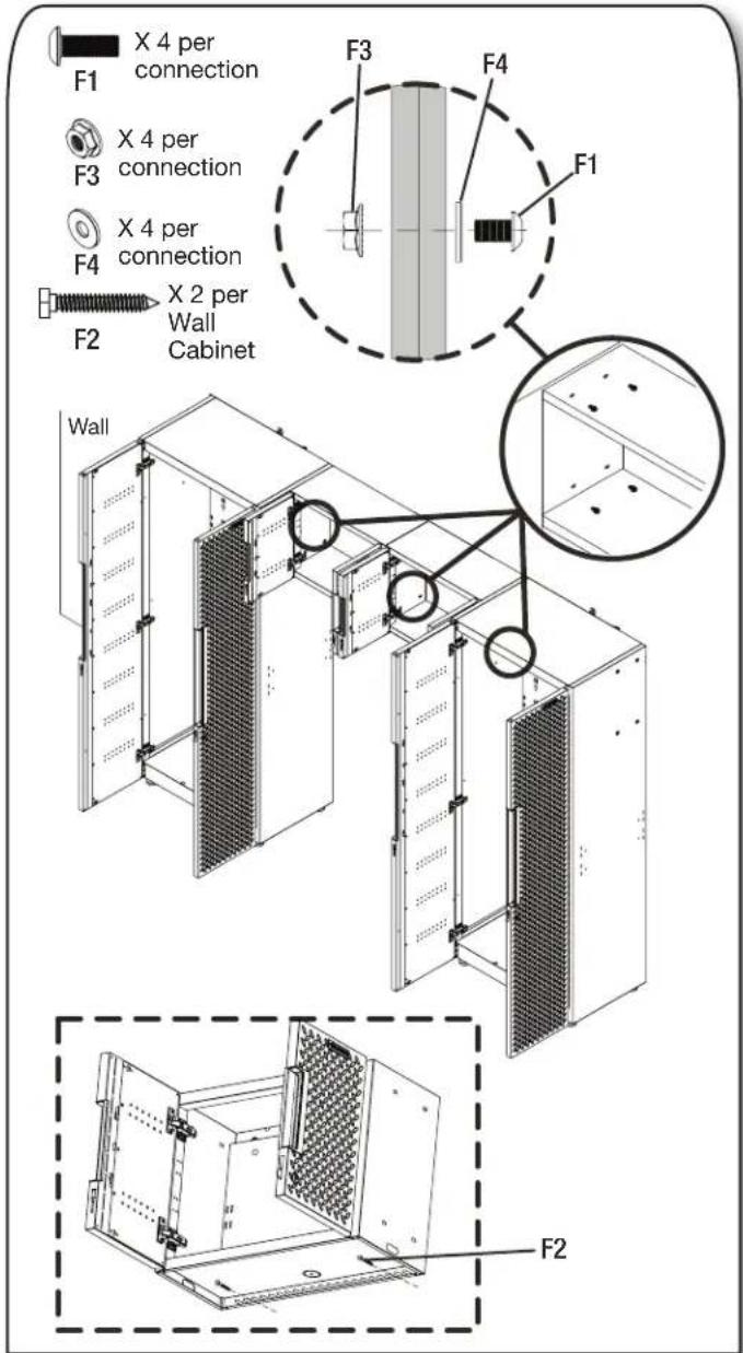
text_image
X 4 per connection F1 F3 X 4 per connection F4 X 4 per connection F2 X 2 per Wall Cabinet F3 F4 F1 Wall F2■Connect the wall cabinets as shown and tighten securely with four M6 x 16 hex socket head screws (F1), four nuts (F3) and four washers (F4) for each side.
■Attach each wall cabinet's bottom to the wall studs with two M6 x 40 hex tapping bolts (F2).
ASSEMBLY INSTRUCTIONS
7. Position the Base Cabinets
IMPORTANT: The M6 x 40 hex tapping bolts should be drilled into a wall stud.
7a. Install the wall bracket.
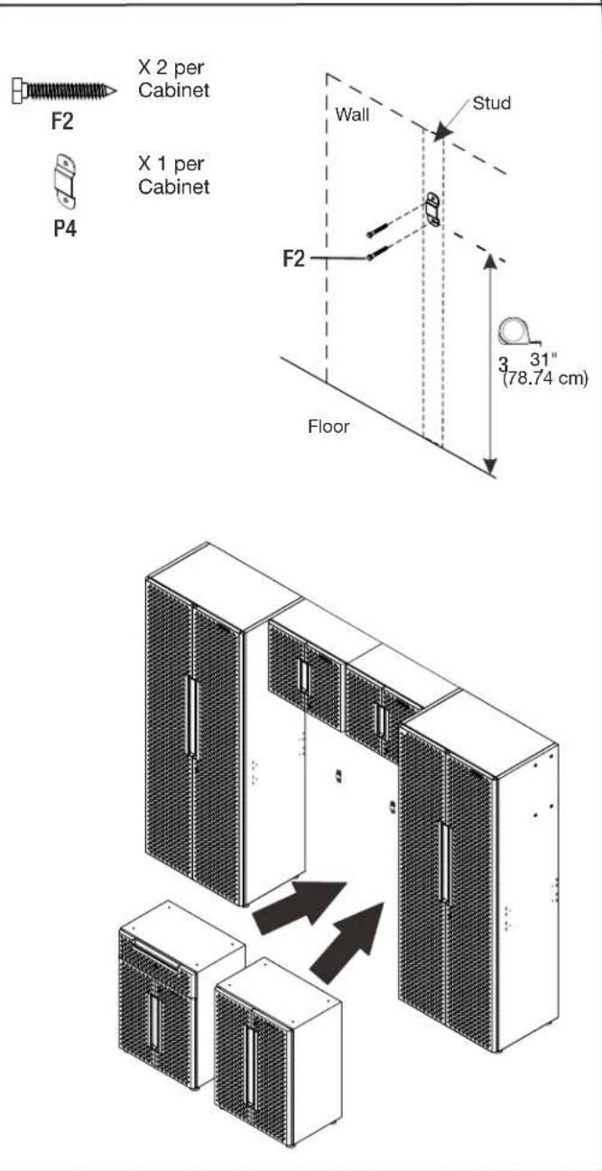
text_image
X 2 per Cabinet X 1 per Cabinet F2 P4 Wall Stud F2 Floor 3 31" (78.74 cm)■Bolt the wall bracket for each base cabinet with two M6 x 40 hex tapping bolts (F2) to a wall stud.
7b. Tie the base cabinet and wall bracket together.
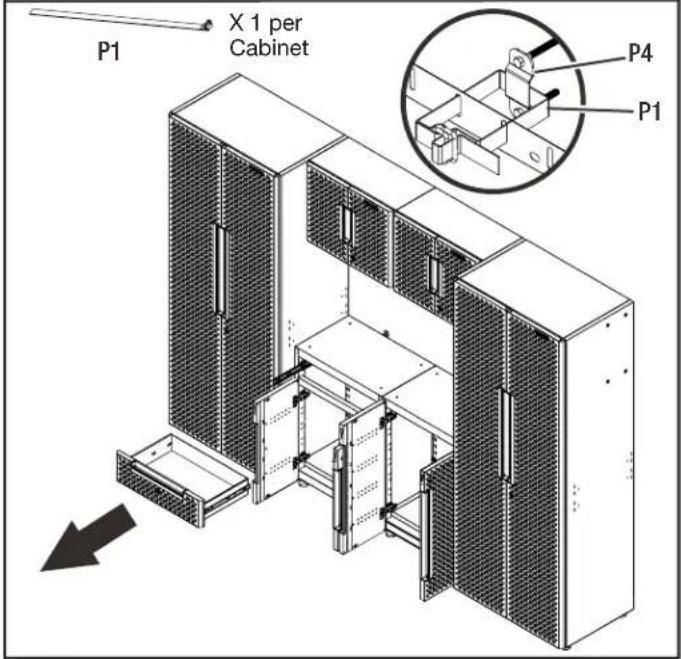
text_image
P1 X 1 per Cabinet P4 P1■Remove the drawer from the 1-drawer 2-door base cabinet. (see instruction on page 16)
■ Fasten the base cabinet by using the wall strap to tie the base cabinet and wall bracket together.
7c. Install the drawer and place the top mats.
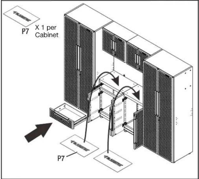
text_image
P7 X 1 per Cabinet P7■Install the drawer back into the 1-drawer 2-door base cabinet. (see instruction on page 16)
■Place the top mats on top of the base cabinets.
ASSEMBLY INSTRUCTIONS
- Install the Closet Rod in the Tall Cabinet
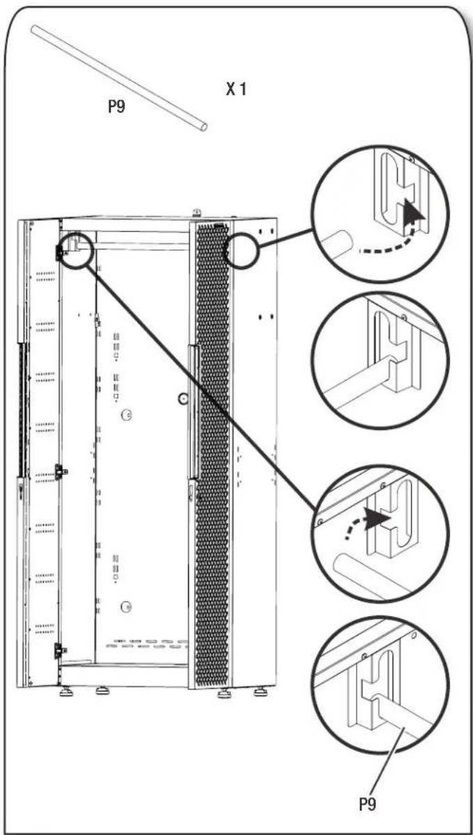
text_image
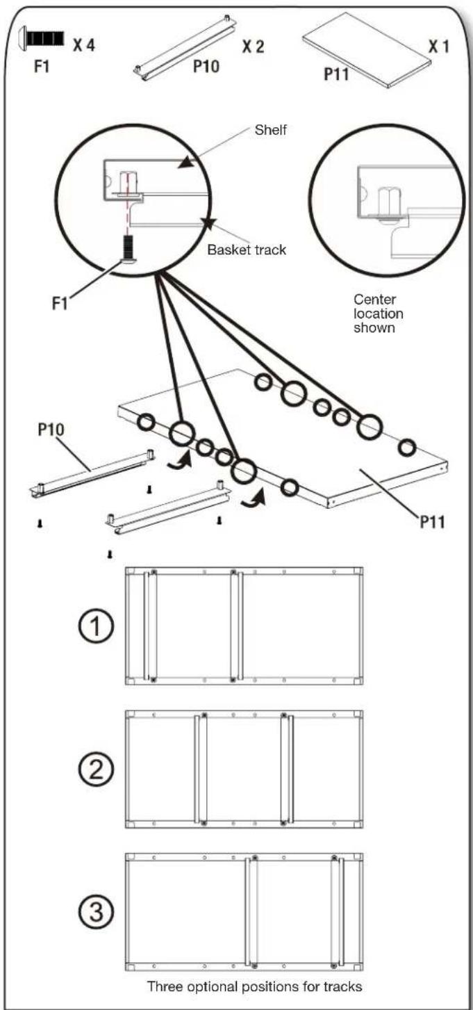
P9 X 1 P9- Install the Basket Tracks in the Tall Cabinet
text_image
F1 X 4 P10 X 2 P11 X 1 Shelf Basket track F1 Center location shown P10 P11 Three optional positions for tracks- Install two tracks to the tall cabinet's shelf bottom with four M6 x 16 hex socket head screws (F1).
NOTE: Each tall cabinet is included with one basket. Additional Flex basket kits are available for purchase to create more storage options. Two baskets can be positioned side by side underneath the tall cabinet's shelf.
ASSEMBLY INSTRUCTIONS
10. Install the Basket
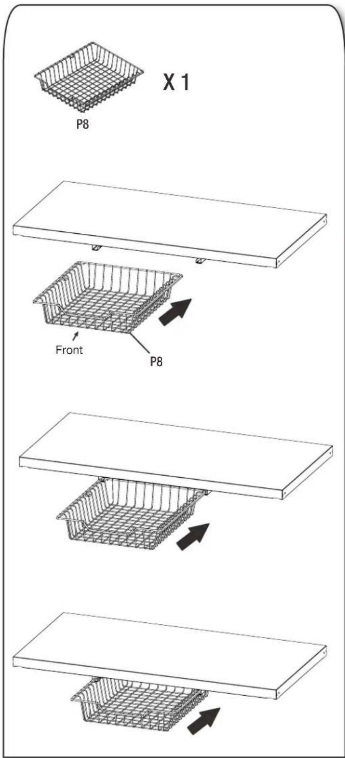
text_image
X 1 P8 Front P8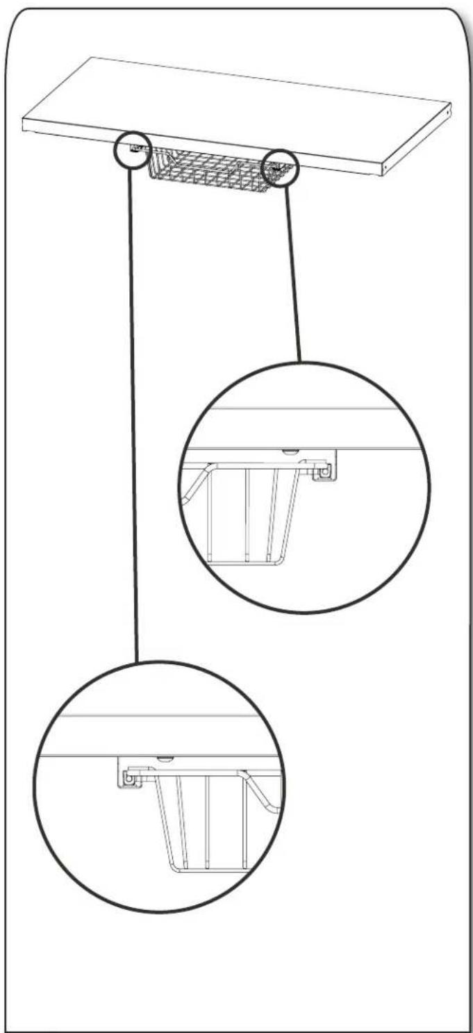
natural_image
Technical line drawing of a suspended platform with two circular insets showing internal components (no text or symbols)■Attach the basket (P8) to the basket tracks (P10) installed already to the tall cabinet shelf's bottom.
INSTALL CABINET TO GLADIATOR® GEARTRACK® CHANNEL
Install the 30" Tall Cabinet
NOTE: Gladiator® Flex Brackets are sold individually and Gladiator® GearTrack® channels are sold separately.
- Install the brackets to the tall cabinet.
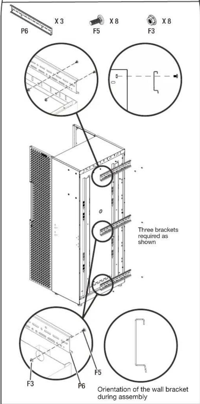
text_image
P6 X 3 F5 X 8 F3 X 8 Three brackets required as shown F3 P6 F5 Orientation of the wall bracket during assembly■ Attach the top bracket to the tall cabinet's back top with four M6 round head square neck bolts (F5) and four M6 flange nuts (F3).
■Attach the center and bottom brackets to the tall cabinet's back respectively with two M6 round head square neck bolts (F5) and two M6 flange nuts (F3).
- Hang the tall cabinet onto the GearTrack® channels.
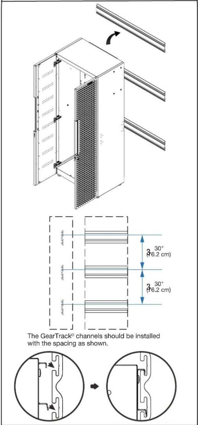
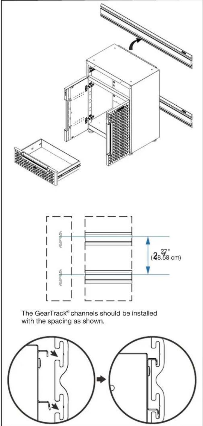
text_image
The GearTrack® channels should be installed with the spacing as shown.■Make sure all three brackets are fully engaged in the slots as shown.
NOTE: . For installation of the Gladiator® GearTrack® channels, please refer to the manual instructions included with the Gladiator® GearTrack® channels.
INSTALL CABINET TO GLADIATOR® GEARTRACK® CHANNEL
Install the 24" Wall Cabinet
NOTE: Gladiator® GearTrack® channels sold separately.
1. Attach two M6 x 16 hex socket head screws to the bracket as shown.
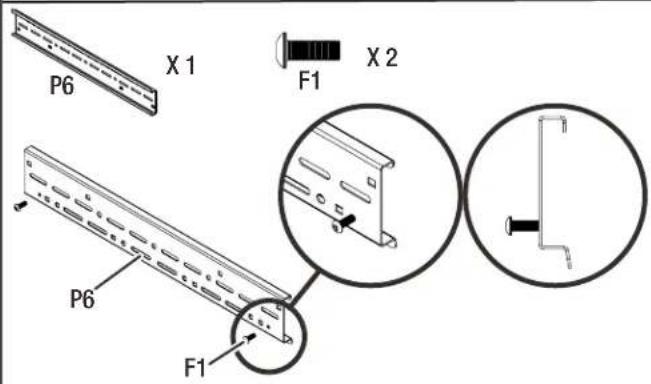
text_image
P6 X 1 F1 X 2 P6 F12. Attach the bracket to the wall cabinet's back top.
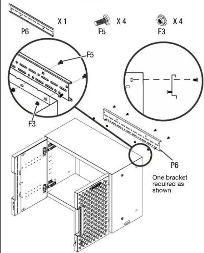
text_image
P6 X 1 F5 X 4 F3 X 4 F5 F3 P6 One bracket required as shown■Attach the bracket to the wall cabinet's back top with four M6 round head square neck bolts (F5) and four M6 flange nuts (F3).
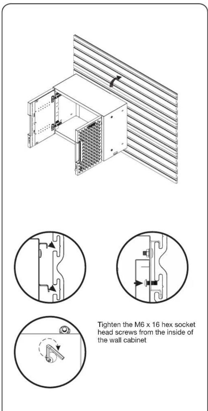
3. Hang the wall cabinet onto the GearTrack® channels.
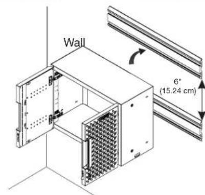
text_image
Wall 6" (15.24 cm)The GearTrack® channels should be installed with the spacing as shown.
natural_image
Pure mechanical cross-section diagram without any text, numbers, or symbols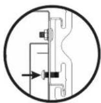
natural_image
Pure mechanical diagram showing a valve or connector without any text, numbers, or symbols
natural_image
Simple line drawing of a mechanical component inside a circle, with no text or symbols present.Tighten the M6 x 16 hex socket head screws from the inside of the wall cabinet
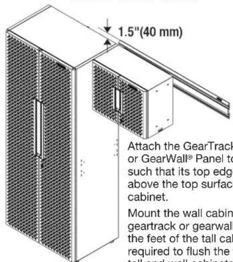
text_image
1.5"(40 mm) Attach the GearTrack or GearWall® Panel to such that its top edge above the top surface cabinet. Mount the wall cabin geartrack or gearwall the feet of the tall cab required to flush the tall and wall cabinets.Attach the GearTrack® Channel or GearWall® Panel to the drywall such that its top edge is 40 mm above the top surface of the tall cabinet.
Mount the wall cabinet onto the geartrack or gearwall. And adjust the feet of the tall cabinet as required to flush the tops of both tall and wall cabinets.
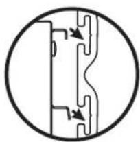
■Make sure the bracket is fully engaged in the wall slots as shown. Tighten the pre-attached M6 x 16 hex socket head screws fully into the bracket and make sure they go into the wall slots.
NOTE: If installing the wall cabinet on GearTrack® channels, a second channel must be installed 6"(15.24cm) below the bottom of the supporting channel so the cabinet will hang level.
NOTE: For installation of the Gladiator® GearTrack® channels, please refer to the manual instructions included with the Gladiator® GearTrack® channels.
INSTALL CABINET TO GLADIATOR® GEARTRACK® CHANNEL
Install the 24" 2-door Base Cabinet
NOTE: Gladiator® Flex Brackets are sold individually and Gladiator® GearTrack® channels are sold separately.
- Install the brackets to the cabinet.
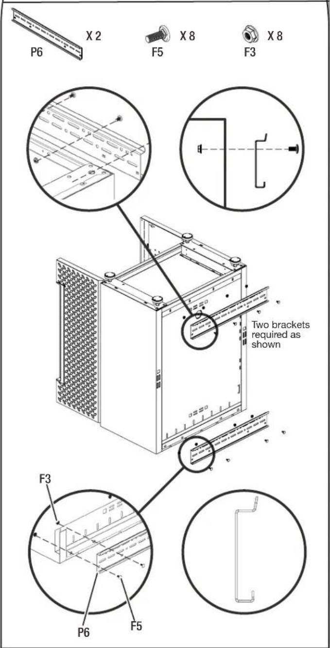
text_image
P6 X 2 F5 X 8 F3 X 8 Two brackets required as shown F3 P6 F5■Temporarily turn the base cabinet upside down as shown.
■ Attach the brackets to the back of the base cabinet as shown with eight M6 round head square neck bolts (F5) and eight M6 flange nuts (F3).
- Hang the base cabinet onto the GearTrack® channels.
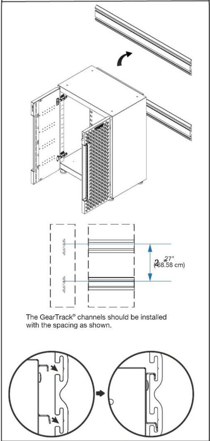
text_image
The GearTrack® channels should be installed with the spacing as shown.■Hang the base cabinet onto the GearTrack® channels. Make sure the two brackets are fully engaged in the slots as shown.
NOTE: . For installation of the Gladiator® GearTrack® channels, please refer to the manual instructions included with the Gladiator® GearTrack® channels.
INSTALL CABINET TO GLADIATOR® GEARTRACK® CHANNEL
Install the 24" 1-drawer 2-door Base Cabinet
NOTE: Gladiator® Flex Brackets are sold individually and Gladiator® GearTrack® channels are sold separately.
- Install the wall brackets to the cabinet.
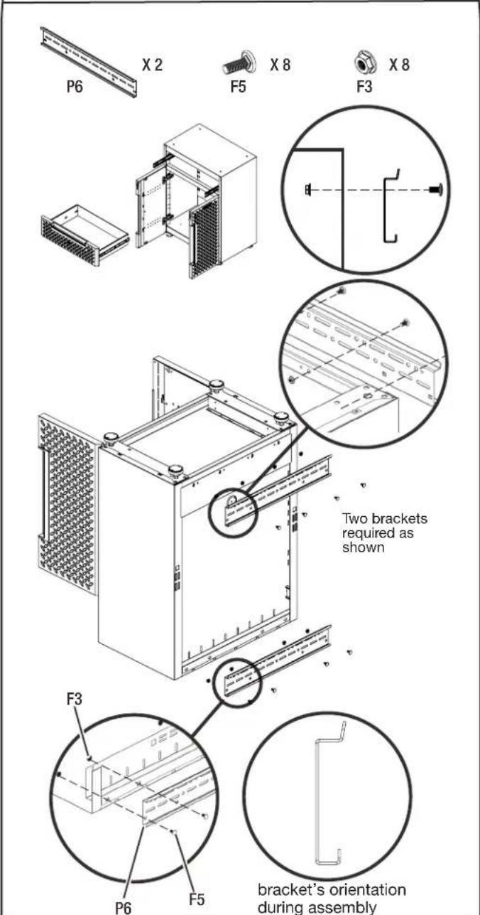
text_image
P6 X 2 F5 X 8 F3 X 8 Two brackets required as shown F3 P6 F5 bracket's orientation during assembly■Remove the drawer from the base cabinet. (See instruction on Page 16)
■Temporarily turn the base cabinet upside down as shown.
■ Attach the brackets to the back of the base cabinet as shown with eight M6 round head square neck bolts (F5) and eight M6 flange nuts (F3).
- Hang the base cabinet onto the GearTrack® channels.
text_image
The GearTrack® channels should be installed with the spacing as shown.■Make sure the two brackets are fully engaged in the slots as shown. Install the drawer back to the base cabinet. (See instruction on page 16)
NOTE: . For installation of the Gladiator® GearTrack® channels, please refer to the manual instructions included with the Gladiator® GearTrack® channels.
INSTALL CABINET TO GLADIATOR® GEARWALL® PANELS
NOTE: Gladiator® Flex Brackets are sold individually and Gladiator® GearWall® panels are sold separately.
NOTE: For installation of the Gladiator® GearWall® panels, please refer to the manual instructions included with the Gladiator® GearWall® panels.
Install the 30" Tall Cabinet
natural_image
Technical line drawing of a server rack cabinet with ventilation grilles and insulation cover (no text or symbols)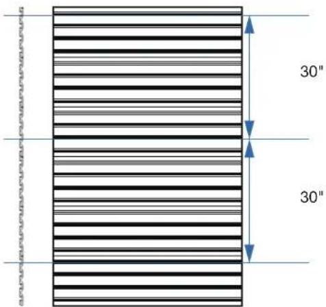
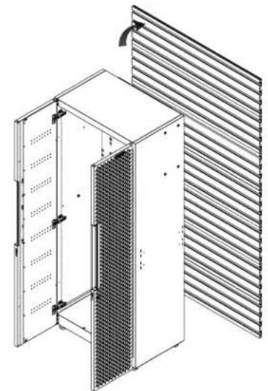
text_image
30" 30"The GearWall ^® panels should be installed with the spacing as shown.
natural_image
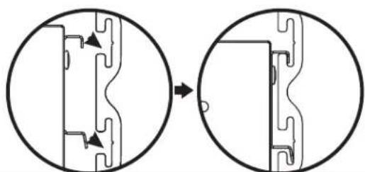
Diagram showing two circular views of a mechanical component before and after assembly, with no visible text or symbols.■ Install three brackets to the tall cabinet. (see instruction on Page 12)
■Hang the tall cabinet onto the GearWall® panels.
■Make sure all three brackets are fully engaged in the slots as shown.
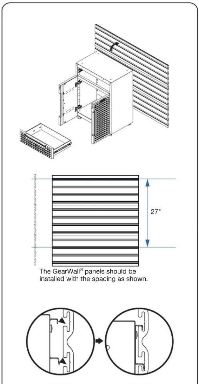
Install the 24" 2-door Base Cabinet
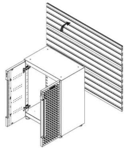
natural_image
Technical line drawing of a modular server rack unit with ventilation grilles and mounting brackets (no text or symbols)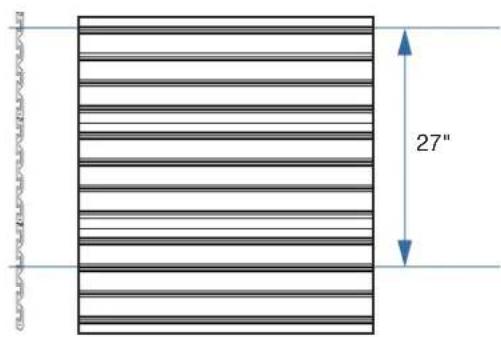
text_image
27"The GearWall ^® panels should be installed with the spacing as shown.
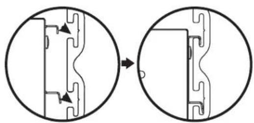
natural_image
Diagram showing two circular views of a mechanical component before and after modification, with no visible text or symbols.■Install two brackets to the base cabinet. (see instruction on Page 14)
■Hang the base cabinet onto the GearWall ^® panels.
■Make sure both brackets are fully engaged in the slots as shown.
INSTALL CABINET TO GLADIATOR® GEARWALL® PANEL
NOTE: Gladiator® Flex Brackets are sold individually and Gladiator® GearWall® panels are sold separately.
NOTE: . For installation of the Gladiator® GearWall® panels, please refer to the manual instructions included with the Gladiator® GearWall® panels.
Install the 24" 1-drawer 2-door Base Cabinet
text_image
The GearWall® panels should be installed with the spacing as shown. 27"■Install two brackets to the base cabinet. (see instruction on Page 15)
■Hang the base cabinet onto the GearWall ^® panels.
■Make sure both brackets are fully engaged in the slots as shown. Install the drawer back to the base cabinet. (See instruction on page 18)
Install the 24" Wall Cabinet
text_image
Tighten the M6 x 16 hex socket head screws from the inside of the wall cabinet■ Install the bracket to the wall cabinet. (see instruction on Page 13)
■Hang the wall cabinet onto the GearWall ^® panels.
■Make sure the bracket is fully engaged in the wall slots as shown. Tighten the pre-attached M6 x 16 hex socket head screws fully into the bracket and make sure they go into the wall slots.
DOOR ADJUSTMENT
Adjusting the Door (if required)
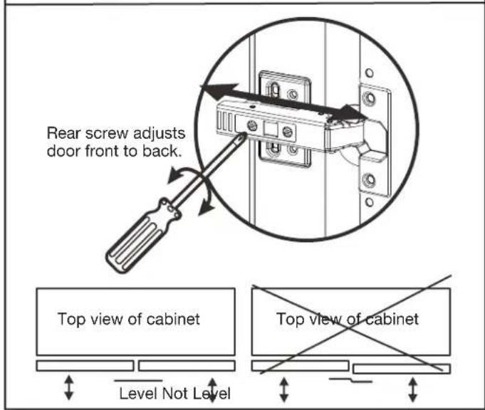
Adjusting the door front to back (if required)
text_image
Rear screw adjusts door front to back. Top view of cabinet Level Not Level Top view of cabinet■Screw the inner screw on the soft closed hinge to adjust the gap between the doors and shell. Ensure the door is always level.
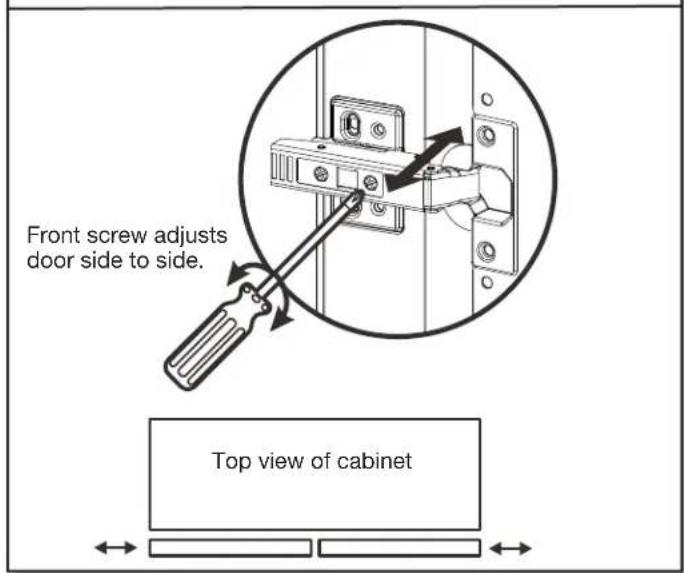
Adjusting the door side to side (if required)
text_image
Front screw adjusts door side to side. Top view of cabinet■Screw the outer screw on the soft closed hinge to adjust the gap between the doors. Ensure the door is always level.
DRAWER REMOVAL AND REPLACEMENT
Drawer removal and replacement
Drawer removal and replacement
text_image
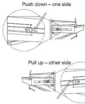
Push down – one side Pull up – other side■DRAWER REMOVAL
Empty the drawer. Pull the drawer out so it's almost fully extended. There are two black release levers, one on each side of the drawer. Pull up the black release lever on one side, while pushing down the black release lever on the other side. While holding the levers in the positions as instructed above, pull the drawer outward until it is released from the drawer slides.
■DRAWER REPLACEMENT
Extend the drawer slides from the cabinet. Insert the brackets on each side of the drawer into the slots in the slides, being careful that they are properly positioned. Once properly inserted, completely close the drawer to set the slides in their proper positions.
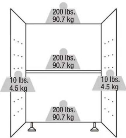
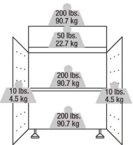
WEIGHT CAPACITY
text_image
200 lbs. 90.7 kg 200 lbs. 90.7 kg 10 lbs. 4.5 kg 10 lbs. 4.5 kg 200 lbs. 90.7 kg24" 2-Door Base Cabinet Max 620 lbs.
text_image
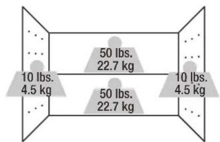
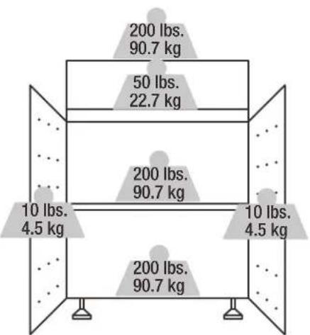
10 lbs. 4.5 kg 50 lbs. 22.7 kg 50 lbs. 22.7 kg 10 lbs. 4.5 kg24" Wall Cabinet Max 120 lbs.
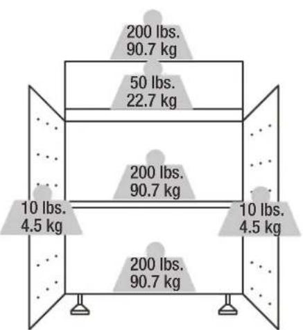
boxplot
| Category | Weight (kg) | |---|---| | Top Box | 200 lbs. | | Top Box | 90.7 kg | | Middle Box | 50 lbs. | | Middle Box | 22.7 kg | | Bottom Box | 10 lbs. | | Bottom Box | 4.5 kg | | Bottom Box | 200 lbs. | | Bottom Box | 90.7 kg | The top box contains two identical weights: 200 lbs. and 90.7 kg, while the bottom box contains two identical weights: 10 lbs. and 4.5 kg.24" 1-Drawer 2-Door Base Cabinet Max 670 lbs.
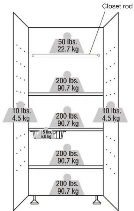
text_image
Closet rod 50 lbs. 22.7 kg 200 lbs. 90.7 kg 10 lbs. 4.5 kg 200 lbs. 90.7 kg 10 lbs. 4.5 kg 15 lbs. 6.8 kg 200 lbs. 90.7 kg 200 lbs. 90.7 kg30" Tall Cabinet Max 870 lbs. (Shelf's maximum load capacity includes the basket weight and load inside the basket)
MAINTENANCE
- Check all the screws and nuts periodically for tightness. Tighten them when necessary.
- Check the wall strap periodically for tightness. Tighten it when necessary.
CARE AND CLEANING
■Periodically clean the surfaces with a soft rag and water.
■ Grease and oil can be removed with most standard cleaning fluids. Use a nonflammable cleaning fluid.
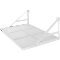
GLADIATOR® FLEX ACCESSORIES
To order accessories, call 1-866-342-4089 and ask for the accessory part number listed below or contact your authorized Gladiator®
GarageWorks dealer. In Canada, Call 1-800-807-6777.
Gladiator® Flex Bracket (Order Part # GANA201BMS) - Allows the cabinet to be mounted on Gladiator® GearTrack® channels.
Gladiator® Flex Caster Kit (Order Part # GANA04CKMX)
Gladiator® Flex Basket Kit (Order Part # GANA12SBMB)
Gladiator® Flex Worktop (Order Part # GANA24HWMX)
WARRANTY
For warranty information:
In the U.S.A. call 1-866-342-4089 or visit our website at
www.GladiatorGW.com
In Canada call 1-800-807-6777 or visit our website at
www.gladiatorgarageworks.ca
Limited Lifetime Parts Warranty for metal parts.
The warranty excludes incidental / inconsequential damages and failure due to misuse, abuse or normal wear and tear.
SÉCURITÉ DE L'ARMOIRE
natural_image
Isometric line drawing of a rectangular electronic device with a grid-patterned panel and central vertical slot (no text or symbols)Armoire murale de 24 po

natural_image
Isometric illustration of a rectangular device with a textured panel and side panel (no text or symbols)natural_image
Isometric line drawing of a rectangular electronic device with a grid-patterned front panel and control panel (no text or symbols)natural_image
Isometric line drawing of a server rack unit with mesh insulation (no text or symbols)Grande armoire de 30 po
ENSEMBLE
natural_image
Pure electrical circuit lines without any symbolsUGS : GANF03WFMTS
natural_image
Pure electrical circuit lines without any symbolsUGS : GANF03WDMTS
natural_image
Pure electrical circuit lines without any symbolsUGS : GANF04WFMTS
natural_image
Technical line drawing of a rectangular metal plate with evenly spaced cutouts and labeled 'PC' at the bottom (no text or symbols on the plate itself)P6
text_image
GLADIATORP7P8P9
natural_image
Isometric wireframe view of a rectangular metal tray with grid pattern (no text or symbols)
natural_image
Simple line drawing of a straight cylindrical rod (no text or symbols)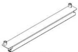
natural_image
Pure technical line drawing of a rectangular metal beam with mounting holes (no text or symbols)P10P11
natural_image
Simple line drawing of a rectangular block (no text or symbols)
P12P13

P14
natural_image
Line drawing of a handheld electric drill (no text or symbols)natural_image
Line drawing of a screwdriver with a flat blade and handle (no text or symbols)natural_image
Diagram of a mechanical device with internal components and directional arrows indicating movement (no text or symbols)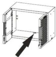
natural_image
Diagram of an open industrial air vent with a black arrow pointing to the outlet (no text or symbols present)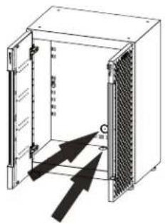
text_image
Technical diagram of an electrical enclosure with labeled components and directional arrows indicating movement or force.
text_image
厨房1 厨房2 厨房3 厨房4
natural_image
Simple line drawing of a tool inside a circular frame, no text or symbols present1

natural_image
Simple line drawing of a circular object with a pointer and arrow, no text or symbols present.2
natural_image
Simple diagram showing two concentric circles with a black arrow pointing to one circle, labeled 'P5' at the bottom left (no text or symbols within the circles)3

natural_image
Simple 3D-rendered ring shape with no text or symbolsnatural_image
Technical line drawing of an open industrial rack unit with internal panel and mounting bracket (no text or symbols)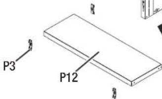
text_image
P3 P12[Non-Text]
INSTRUCTIONS D'ASSEMBLAGE
text_image
X 1 P8 Avant P8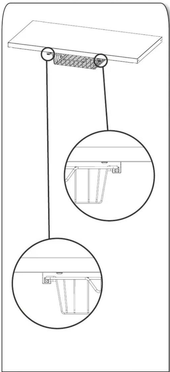
natural_image
Technical line drawing of a suspended platform with two circular insets showing internal components (no text or symbols)natural_image
Technical line drawing of a cabinet with ventilation grilles and metal racks, showing internal structure and rotation arrow (no text or symbols)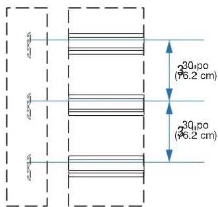
text_image
3Q1po (76.2 cm) 3Q1po (76.2 cm)natural_image
Diagram showing a mechanical component before and after transformation, with no visible text or symbols.text_image
P6 X 1 F1 X 2 P6 F1natural_image
Three circular diagrams showing mechanical assembly or component views with arrows indicating direction (no text or symbols)natural_image
Technical line drawing of a server rack with ventilation grilles and insulation panels (no text or symbols)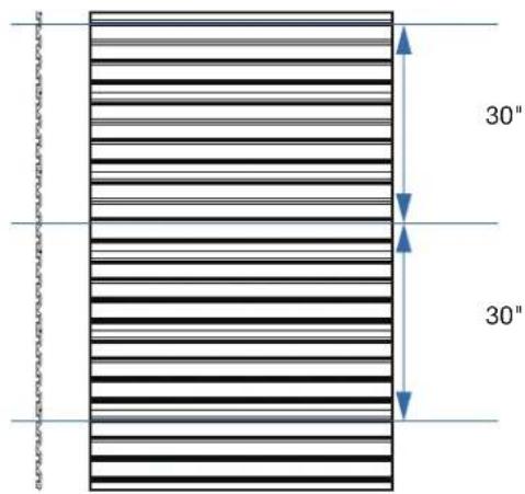
text_image
30" 30"natural_image
Diagram showing two circular views of a mechanical component before and after assembly, with no visible text or symbols.natural_image
Technical line drawing of a modular air vent or rack unit with a grid-patterned panel and slatted top wall (no text or symbols)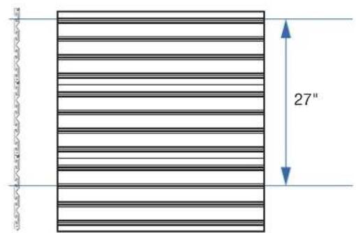
text_image
27"natural_image
Diagram showing two circular views of a mechanical or electrical component, with arrows indicating direction (no text or symbols present)natural_image
Technical line drawing of an industrial enclosure with internal components and a separate storage unit (no text or symbols)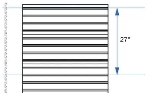
text_image
27"natural_image
Diagram showing two views of a mechanical component before and after modification, with no visible text or symbols.natural_image
Technical line drawing of an open industrial enclosure with a grid-patterned panel, mounted on a wall (no text or symbols)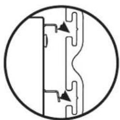
natural_image
Pure mechanical cross-section diagram without any text, numbers, or symbols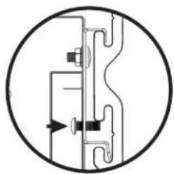
natural_image
Pure mechanical diagram showing pipe connections without any text, numbers, or symbols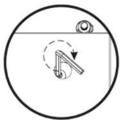
natural_image
Simple line drawing of a mechanical lever mechanism inside a circular frame (no text or symbols)text_image
200 lbs. 90.7 kg 200 lbs. 90.7 kg 10 lbs. 4.5 kg 10 lbs. 4.5 kg 200 lbs. 90.7 kgtext_image
10 lbs. 4.5 kg 50 lbs. 22.7 kg 50 lbs. 22.7 kg 10 lbs. 4.5 kgArmoire murale de 24 po Max. 120 lb
boxplot
| Category | Weight (kg) | |---|---| | Top Box | 200 lbs. | | Top Box | 90.7 kg | | Middle Box | 50 lbs. | | Middle Box | 22.7 kg | | Bottom Box | 10 lbs. | | Bottom Box | 4.5 kg | | Bottom Box | 200 lbs. | | Bottom Box | 90.7 kg | The chart displays a single data series with two distinct weight values: 200 lbs. and 90.7 kg. The top box contains 200 lbs. and 90.7 kg, while the middle and bottom boxes contain 10 lbs. and 4.5 kg respectively. Each box includes a small dot indicating a specific weight or component within the top box.text_image
Tringle 50 lbs. 22.7 kg 200 lbs. 90.7 kg 10 lbs. 4.5 kg 200 lbs. 90.7 kg 10 lbs. 4.5 kg 15 lbs. 6.8 kg 200 lbs. 90.7 kg 200 lbs. 90.7 kgnatural_image
Isometric line drawing of a rectangular electronic device with a grid-patterned front panel and internal slot (no text or symbols)Gabinete de pared de 24"

natural_image
Isometric illustration of a rectangular device with a mesh panel and a vertical slot, no text or symbols present.natural_image
Isometric line drawing of a rectangular electronic device with a grid-patterned front panel and control panel (no text or symbols)natural_image
Isometric line drawing of a server rack cabinet with mesh panels (no text or symbols)Gabinete alto de 30"
SUITES
natural_image
Pure electrical circuit lines without any symbolsSKU: GANF03WFMTS
natural_image
Pure electrical circuit lines without any symbolsSKU: GANF03WDMTS
natural_image
Pure electrical circuit lines without any symbolsSKU: GANF04WFMTS
natural_image
Pure electrical circuit lines without any symbolsSKU: GANF05WFMTS
natural_image
Pure electrical circuit lines without any symbolsSKU: GANF04WCMTS
natural_image
Technical line drawing of a rectangular metal plate with evenly spaced cutouts (no text or symbols)P6
text_image
V-GLADIATORP7P8P9
natural_image
Isometric wireframe view of a rectangular metal tray with grid pattern (no text or symbols)
natural_image
Simple line drawing of a straight cylindrical rod (no text or symbols)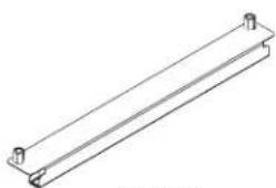
natural_image
Pure technical line drawing of a mechanical bracket or support structure (no text or symbols)P10P11

natural_image
Simple line drawing of a rectangular plate or shelf (no text or symbols)
P12P13

P14
natural_image
Line drawing of a handheld electric drill (no text or symbols)natural_image
Line drawing of a screwdriver with a flat blade and textured handle (no text or symbols)natural_image
Isometric technical drawing of a rectangular device with grid pattern and mounting base (no text or symbols)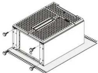
natural_image
Isometric technical drawing of a rectangular enclosure with grid pattern and mounting flanges (no text or symbols)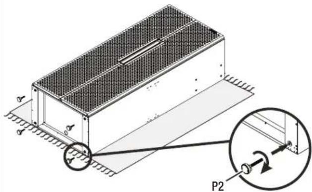
text_image
Technical diagram of a mechanical assembly with labeled components and directional arrows, including a magnified inset showing P2 component.natural_image
Technical diagram of a mechanical or electrical enclosure with internal components and directional arrows (no text or symbols)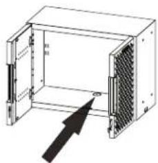
natural_image
Diagram of an open industrial rack unit with a mesh panel and directional arrow (no text or symbols)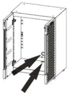
text_image
Technical diagram of an electrical enclosure with labeled components and directional arrows indicating movement or force.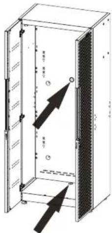
text_image
Technical diagram of an open electrical cabinet with labeled internal components and directional arrows indicating movement or force.
natural_image
Simple line drawing of a circular object with a pointer and arrow, no text or symbols present.1

natural_image
Simple line drawing of a circular object with a pointer and arrow, no text or symbols present.2
natural_image
Simple diagram showing two concentric circles with a black arrow pointing to one circle, labeled 'P5' at the bottom left (no text or symbols within the circles)3

natural_image
Simple circular ring shape with no text or symbolsnatural_image
Isometric line drawing of an open industrial rack unit with internal components and a black arrow indicating direction (no text or symbols)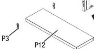
text_image
P3 P128
INSTRUCCIONES DE ENSAMBLAJE
natural_image
Technical line drawing of a suspended platform with two circular insets showing internal components (no text or symbols)text_image
P6 X 1 F1 X 2 P6 F1natural_image
Three circular diagrams showing mechanical or electrical component views with arrows indicating direction (no text or symbols)text_image
200 lbs. 90.7 kg 200 lbs. 90.7 kg 10 lbs. 4.5 kg 10 lbs. 4.5 kg 200 lbs. 90.7 kgtext_image
10 lbs. 4.5 kg 50 lbs. 22.7 kg 50 lbs. 22.7 kg 10 lbs. 4.5 kgGabinete de pared de 24" Máx. 120 lb.
boxplot
| Category | Weight (kg) | |---|---| | Top Box | 200 lbs. | | Top Box | 90.7 kg | | Middle Box | 50 lbs. | | Middle Box | 22.7 kg | | Bottom Box | 10 lbs. | | Bottom Box | 4.5 kg | | Bottom Box | 200 lbs. | | Bottom Box | 90.7 kg | The top box contains two identical weights: 200 lbs. and 90.7 kg, while the bottom box contains two identical weights: 10 lbs. and 4.5 kg.text_image
Barra de gabinete 50 lbs. 22.7 kg 200 lbs. 90.7 kg 10 lbs. 4.5 kg 200 lbs. 90.7 kg 15 lbs. 6.8 kg 200 lbs. 90.7 kg 200 lbs. 90.7 kg®/TM ©2023 Gladiator. All rights reserved. Used under license in Canada.