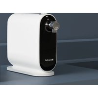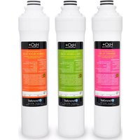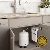
Capella RC250 - Water filter Brondell - Free user manual and instructions
Find the device manual for free Capella RC250 Brondell in PDF.


User questions about Capella RC250 Brondell
0 question about this device. Answer the ones you know or ask your own.
Ask a new question about this device
Download the instructions for your Water filter in PDF format for free! Find your manual Capella RC250 - Brondell and take your electronic device back in hand. On this page are published all the documents necessary for the use of your device. Capella RC250 by Brondell.
USER MANUAL Capella RC250 Brondell
natural_image
Line drawing of a water treatment tank with multiple pressure vessels and piping (no text or symbols)Contents
Read this Owner's Manual for correct installation, use, and maintenance of this product. After reading and completing installation, keep this manual in a place that is easily accessible.
GENERAL INFO
01 SAFETY INFORMATION
02 Button Battery Warning
TDS Meter Information
03 PRODUCT INFORMATION
03 Product Features
04 Product Components
05 Capella Water Flow Diagram
06 The Three-Stage Filtration Process
TECHNICAL INFORMATION
24 TECHNICAL INFORMATION
24 Product Specifications
25 Performance Data Sheet
29 Troubleshooting
31 Warranty
32 Contact
PRODUCT INSTALLATION
07 PRODUCT INSTALLATION
07 Step 1: T-Valve Installation
08 Step 2: Faucet Installation
11 Step 3: Drain Clamp Installation
13 Step 4: Filter Head Connection Assembly Installation
14 Step 5: Filter Installation
15 Step 6: Water Storage Tank Prep and Using "Quick Connectors"
16 Step 7: Connecting the Tubing
TRANSLATIONS
33 SPANISH
67 FRENCH
OPERATION
18 PREPARING FOR USE
18 Checking for Leaks
18 Flushing the System
19 Water Pressure
20 MAINTENANCE
20 Filters & Filter Change Indicators
21 Filter Replacement
23 Extended Non-Use
SAFETY INFORMATION (IMPORTANT SAFEGUARDS)
READ ALL INSTRUCTIONS BEFORE USING
BE CAREFUL TO KEEP THIS SAFETY INFORMATION. PLEASE READ THIS INFORMATION TO PREVENT PROPERTY LOSS AND ENSURE SAFETY.

WARNING
If not observed, serious physical injury or property damage may occur as a result. Read all the instructions before using or installing the Capella. Never disassemble, repair, or reconstruct the filter head housing. This may cause the product to fail.
- Never unscrew the filters while the product is in use. This may cause failure due to high water pressure, or it may cause a water leak.
- Do not install near radiators. This may cause fire, or the product could be damaged, resulting in leakage.

CAUTION
If not observed, physical injury or property damage may occur as a result.
- Use or place the unit on a level area, and do not apply force to the unit. This may cause physical injury and/or damage to the product that may void your warranty.
- Turn the water supply off at the T-valve if the filter system will not be used for an extended period of time.
- Especially during very cold weather, the water pressure may rise and may cause a water leak.
- Replace the filters according to their scheduled replacement intervals. If one or more of the filters are exhausted, the purification quality will diminish.
- When replacing the filter or moving the product, do not pull on the water supply hose. The water supply hose may become detached, damaged, or the quick connection coupling may be weakened.
- If a water leak occurs while using the product, or the area around the product is wet, turn the water supply valve off immediately.
BUTTON BATTERY WARNING TDS METER INFORMATION
Button battery warning:
- Remove and immediately recycle or dispose of used batteries according to local regulations and keep away from children. Do NOT dispose of batteries in household trash or incinerate.
• Even used batteries may cause severe injury or death. - Call a local poison control center for treatment information.
• Used Battery CR2032, DC3V
• Non-rechargeable batteries are not to be recharged. - Do not force discharge, recharge, disassemble, heat above 60°C (140°F) or incinerate. Doing so may result in injury due to venting, leakage or explosion resulting in chemical burns.
- Ensure the batteries are installed correctly according to polarity (+ and -)
- Do not mix old and new batteries, different brands, or types of batteries, such as alkaline, carbon-zinc, or rechargeable batteries.
- Remove and immediately recycle or dispose of batteries from equipment not used for an extended period of time according to local regulations.
- Always, completely secure the battery compartment. If the battery compartment does not close securely, stop using the product, remove the batteries and keep them away from children.

WARNING
- INGESTION HAZARD: This product contains a button cell or coin battery.
- DEATH or serious injury can occur if ingested.
- A swallowed button cell or coin battery can cause Internal Chemical Burns in as little as 2 hours.
- KEEP new and used batteries OUT OF REACH OF CHILDREN.
- Seek immediate medical attention if a battery is suspected to be swallowed or inserted inside any part of the body.
- Battery: CR2032. DC3V.

TDS meter information:
Generally, Reverse Osmosis systems lower TDS readings by as much as 90% when compared to tap water readings. This is a normal working range. For example, if your tap water TDS reading is 100, then a normal TDS reading for the RO filtered water is in the range of 0–10. If the TDS reading for the RO filtered water is higher than 15% of normal tap water, this indicates it's time for a filter change, including RO membrane.
Important note about TDS meters and testers.
Q: When I use a Total Dissolved Particle (TDS) reader to test my water after it goes through the Capella, why don't the levels of dissolved particles go down or decrease? I don't think the product is working.
Three-Stage Filtration Featuring E2RO
(Eco-Efficient Reverse Osmosis) Membrane
More efficient than traditional RO systems: Capella is up to 20 times more efficient than conventional RO systems, featuring a wastewater to filtered water ratio of 1:1.
6 to 24 Month Filter Lifespan
Simplified maintenance and low cost of operation:
- 1st Stage Activated Carbon Plus Filter: 6 months
• 2nd Stage E2RO Membrane Filter: 24 months
• 3rd Stage Carbon Block Filter: 6 months
Easy Quick Change Filter Replacement
Special “twist and seal” filter system makes changing your filters a breeze.
Chrome Air Gap Faucet with Integrated LED
Filter Change Indicator
Air gap faucet prevents backflow, and the intuitive LED indicator reminds you when it's time to change your filters.
Easy DIY Installation
Pre-installed faucet tubing and “quick-connect” water supply connections simplify installation.
One Year Warranty
Backed by Brondell's commitment to superior customer service and support.
Product Components
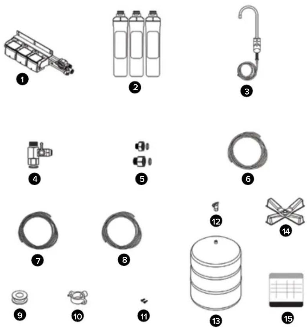
- Filter Head Connector Assembly
- 3 Filters:
a. Activated Carbon Plus Filter
b. E2RO Membrane Filter
c. Carbon Block Filter
- Air Gap Faucet with LED Indicator & 1/4" Blue Tubing
- Water Supply T-Valve with Rubber Washer (3/8" connection)
-
T-Valve Adapters with Rubber Washers (3/8" to 1/2")
-
1/4" Water Supply Tubing (White)
- 3/8" Drain Tubing (Black)
- 1/4" Brine Input Tubing (Orange)
- Teflon Tape
- Drain Clamp
- Mounting Screws (2x)
- Tank Ball Valve
- Reverse Osmosis Pressurized Tank
- Tank Stand
- Filter Change Reminder Sticker
Capella Waterflow Diagram
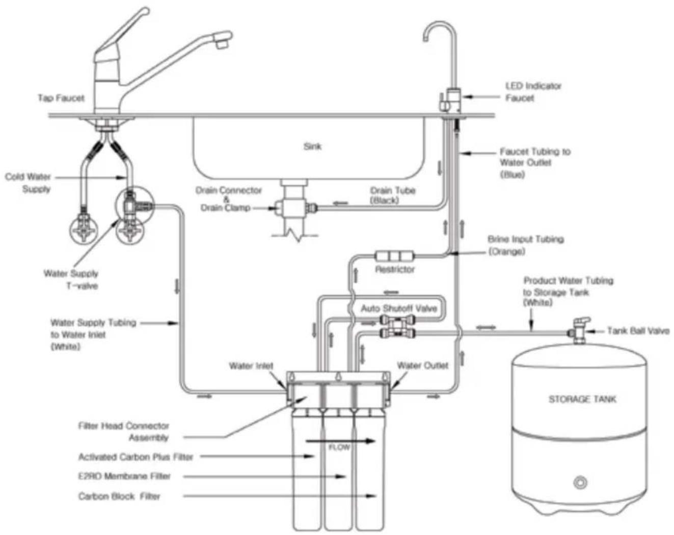
flowchart
graph TD
    A["Tap Faucet"] --> B["Cold Water Supply"]
    B --> C["Water Supply T-valve"]
    C --> D["Water Supply Tubing to Water Inlet (White)"]
    D --> E["Water Inlet"]
    E --> F["Water Outlet"]
    F --> G["Water Supply Tube"]
    G --> H["Drain Connector & Drain Clamp"]
    H --> I["Drain Tube (Black)"]
    I --> J["Drain Indicator Faucet"]
    J --> K["Faucet Tubing to Water Outlet (Blue)"]
    K --> L["Brine Input Tubing (Orange)"]
    L --> M["Product Water Tubing to Storage Tank (White)"]
    M --> N["Tank Ball Valve"]
    N --> O["STORAGE TANK"]
    P["Filter Head Connector Assembly"] --> Q["Activated Carbon Plus Filter"]
    Q --> R["E2RD Membrane Filter"]
    R --> S["Carbon Block Filter"]
    S --> T["Water Outlet"]
    T --> U["Water Supply"]
    U --> V["Restrictor"]
    V --> W["Auto Shutoff Valve"]
    W --> X["Water Inlet"]
    X --> Y["Flow"]
Backside View
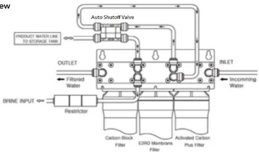
flowchart
graph TD
    A["Product Water Line to Storage Tank"] --> B["Auto Shutoff Valve"]
    B --> C["Outlet"]
    C --> D["Inlet"]
    D --> E["Incommining Water"]
    F["BRINE INPUT"] --> G["Restrictor"]
    G --> H["Carbon Block Filter"]
    G --> I["E2RO Membrane Filter"]
    G --> J["Activated Carbon Plus Filter"]
The Three-Stage Filtration Process
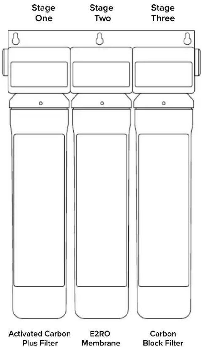
text_image
Stage One Stage Two Stage Three Activated Carbon Plus Filter E2RO Membrane Carbon Block FilterStage One: Activated Carbon Plus Filter The Activated Carbon Plus filter reduces particulate materials such as sand, rust, and fine particles from the water supply. This first stage also acts as a pre-filter protecting and extending the life of the following filters.
Stage Two: E2RO Membrane Filter The Eco-Efficient Reverse Osmosis Membrane filter works by pushing water through a semi-permeable membrane, thereby separating water molecules from contaminants in tap water. The powerful E2RO Membrane significantly reduces pollutants such as heavy metals, cysts, fluoride, arsenic, industrial chemicals, and more. With its unique flow structure, the E2RO Membrane also utilizes less feed water and is more efficient than traditional RO filters.
Stage Three: Carbon Block Filter
The final stage in the filtration process, the Carbon Block filter further reduces any lingering water contaminants such as chlorine and volatile organic compounds (VOCs), improving the overall taste and odor of the dispensed water.
Step 1: T-Valve Installation

DO NOT INSTALL THE FILTER HEAD CONNECTION ASSEMBLY FURTHER THAN 12 FEET AWAY FROM EITHER THE WATER SUPPLY VALVE OR THE INDICATOR FAUCET.
Avoid unnecessary slack in the supply hoses when connecting to the water supply, Filter Head Connection Assembly, or Indicator Faucet. Do not install in direct sunlight or a place where it will be directly exposed to freezing temperatures.
NOTE: Be sure to install the T-Valve on the cold water supply line. Running hot water through the Capella will damage the filters.
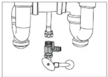
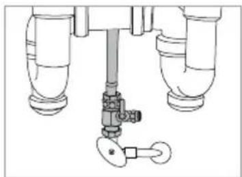
- Close the cold-water supply valve. Place a bucket or similar item underneath the valve to catch any water that may spill out during installation.
- Unscrew the hose that connects the cold-water supply valve to the existing tap water faucet.
- Ensure the rubber washer is inside the T-Valve Adapter, and then screw the adapter onto the cold-water supply valve.
NOTE: If the water supply valve is larger than the 38 " connection on the T-valve, use the included 12 " Valve Adapters with Rubber Washers to connect the T-valve and the water supply hose.
- Screw the cold-water supply hose to the top of the T-valve closed.
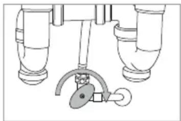
natural_image
Diagram of a mechanical or electrical component with three identical pipes and a central valve (no text or symbols)Step1
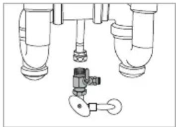
natural_image
Technical line drawing of a mechanical assembly with pipes and a valve (no text or symbols)Step 3
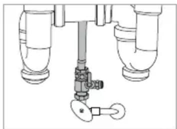
natural_image
Technical line drawing of a mechanical valve assembly with three pipes and a key (no text or symbols)Step 4
Step 2: Air Gap Faucet Installation
Before Installation
You will need an existing faucet hole at least 1-inch in diameter in the sink or countertop to install the supplied filtered water faucet. You may also replace an existing kitchen sprayer, soap dispenser, or plug already on the countertop or sink.
NOTE: If drilling a new hole is required for the faucet installation, please consult a professional. Brondell will not be liable for any damages, including those to the sink or countertop, due to installation of the faucet or drilling a hole. Please find answers to Frequently Asked Questions (FAQs) and installation videos on brondell.com.
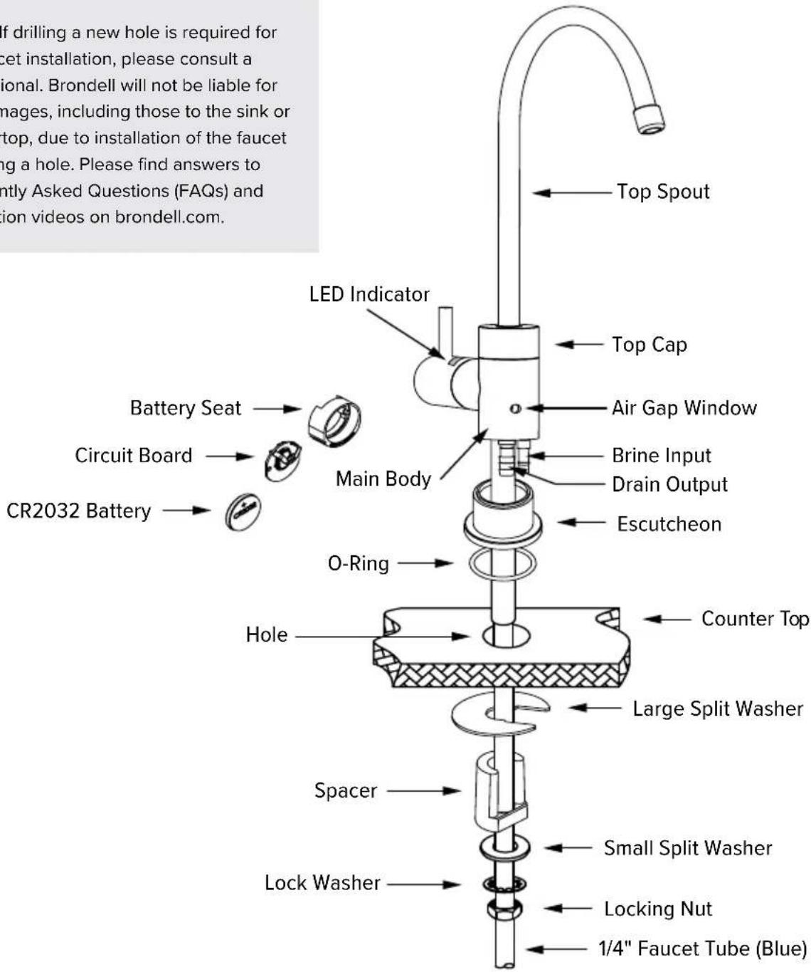
text_image
If drilling a new hole is required for cet installation, please consult a ional. Brondell will not be liable for images, including those to the sink or top, due to installation of the faucet ing a hole. Please find answers to ntly Asked Questions (FAQs) and ion videos on brondell.com. LED Indicator Top Spout Top Cap Battery Seat Circuit Board CR2032 Battery Main Body Air Gap Window Brine Input Drain Output Escutcheon O-Ring Counter Top Hole Large Split Washer Spacer Small Split Washer Lock Washer Locking Nut 1/4" Faucet Tube (Blue)Step 2: Air Gap Faucet Installation
Faucet Installation
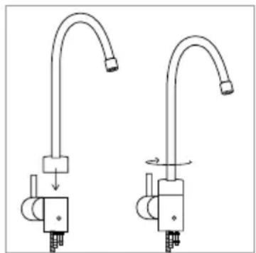
- Unpack the faucet, and insert the Top Spout into the Main Body by pushing down until inserted, then screw the Top Cap clockwise until secured in place.
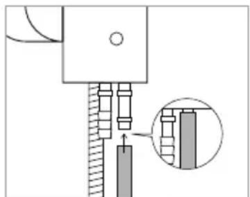
- Cut zip tie on the pre-installed 1/4-inch blue water connection tubing, and unroll to straighten. Be careful not to cut the tube when removing the zip tie.
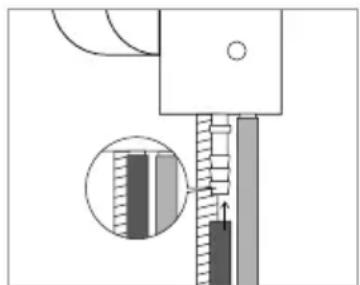
- Connect the 1/4-inch orange brine input tubing. Firmly insert one end into the 1/4-inch brass brine input connector underneath the faucet. Be sure that the tube is fully inserted over the barb until it can't go further. Pull on the tube to ensure the tube is securely in place and does not come off. The opposite end of the orange tube will connect to the flow restrictor later (see instructions on page 16).
- Connect the 3/8-inch black drain tubing. Firmly insert one end into the 3/8-inch brass drain output connector under the faucet. Be sure that the tube is fully inserted over the barb until it can't go further. Pull on the tube to ensure the tube is securely in place and does not come off. The opposite end of the black tube will connect to the drain clamp later (see instructions on pages 11-12).
Both tubes should now be securely connected.
natural_image
Two identical hand-painted illustrations of a shower faucet with no text or symbolsStep 1
natural_image
Mechanical assembly diagram showing a shaft and housing with a magnified inset of a component detail (no text or symbols)Step 3
natural_image
Mechanical assembly diagram showing a piston-cranked mechanism with a magnified inset of the shaft (no text or symbols)Step 4
Step 2: Air Gap Faucet Installation
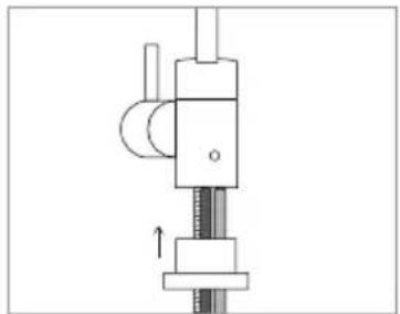
- Attach the Escutcheon to the Main Body by inserting the blue faucet tubing, orange brine input tubing, and black drain tubing (3 tubes) through the Escutcheon. Slide the Escutcheon all the way up until connected to the Main Body.
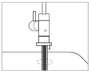
- Install the faucet on top of the countertop or sink, and feed all three tubes through the hole to the cabinet below.
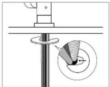
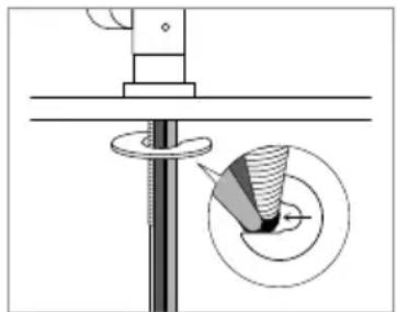
- Slide the large, metal Split Washer around the tubes and metal shaft against the bottom of the countertop or sink hole. The open split should be facing against the metal shaft.
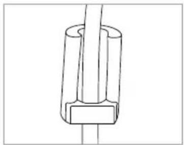
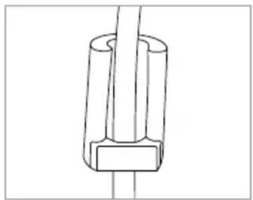
- Install the Spacer with the open-ended hole facing up by sliding the blue tube through as shown. This will keep the blue tube separate from the orange and black tubes.
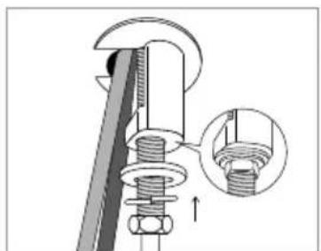
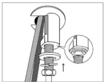
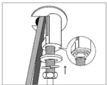
- Install the small, metal Split Washer, Lock Washer, and Locking Nut through the blue tube and tighten until the faucet is firmly in place. The faucet is now installed.
- Pull the plastic tab out from the Battery Seat to activate the LED Indicator. The LED light will blink red once then blue once, then it will be ready for use.
natural_image
Mechanical assembly diagram showing a piston and shaft assembly (no text or labels)Step 5
natural_image
Pure mechanical diagram showing a vertical rod inserted into a cylindrical component, with no text or symbols present.Step 6
natural_image
Technical diagram showing a mechanical assembly with a rotating component and a magnified inset (no text or symbols)Step 7
natural_image
Pure technical line drawing of a mechanical component with no text or symbolsStep 8
TIP: Depending on the amount of space underneath your sink, you may need to cut and shorten some of the tubing based on your needs. When cutting, use sharp scissors or a cutting knife for a clean cut. The opening edge of the tube should be even and clean. If the opening is frayed or crimped, this may affect the flow of the water running through the tube.
natural_image
Mechanical assembly diagram showing a bolt and nut assembly with a magnified inset detail (no text or labels)Step 9
Step 3: Drain Clamp Installation
Before Installation
You will need to have these tools (not included) for the following installation: 1) drill, 2) 1/4-inch drill bit, and 3) 3/8-inch drill bit

WARNING: This step may require drilling into the existing drain pipe. Please seek professional help when completing this step, and always wear safety protection including safety goggles!
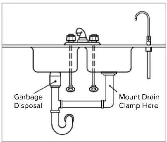
- Locate a suitable area on the sink drain pipe to install the provided drain clamp.
NOTE: Select a location for the drain hole based on the design of the plumbing. It should be installed above the trap and on the vertical or horizontal tail piece. Locate the drain connection away from the garbage disposal. See example to the right.
text_image
Garbage Disposal Mount Drain Clamp HereStep 1
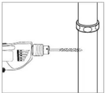
- You will need to drill a 3/8-inch hole in the drain pipe to install the drain clamp. Use a 1/4-inch drill bit, and carefully drill a pilot hole in the drain pipe. Use a 3/8-inch drill bit to enlarge the hole. Clean the debris from the pipe and the hole before continuing.

DO NOT drill all the way through the pipe.
natural_image
Technical line drawing of a mechanical tool interacting with a cylindrical component (no text or symbols)Step 2
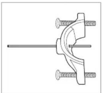
- Find the half of the drain clamp with the hole in its center. Take the foam gasket piece included with the hardware pack and remove the adhesive backing. Align the foam gasket hole to the hole on the drain clamp, and stick the adhesive to the inner wall of the drain clamp half.
a. Insert a screwdriver, straw, or pencil through the hole on the drain saddle to use as a guide.
natural_image
Mechanical clamp assembly diagram with no visible text or symbolsStep 3a
Step 3: Drain Clamp Installation
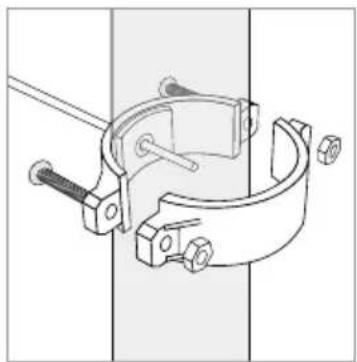
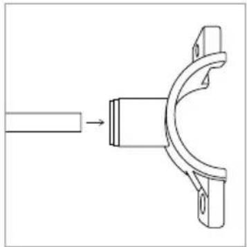
b. Insert the end of the guide into the 3/8-inch hole in the drain pipe, and slide the clamp with the foam against the pipe, lining up both holes. Take the back half of the drain clamp and position it against the back side of the drain pipe. Screw the bolts through both halves of the drain clamp, and apply the nuts to secure. Do not over-tighten.
c. Once the drain clamp is secure on the pipe, remove the guide.
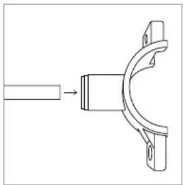
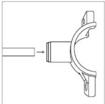
- Take the end of the 3/8-inch black drain tube from the faucet, and insert into the 3/8-inch Quick Connector on the drain clamp and push firmly in place.
natural_image
Technical line drawing of a mechanical clamp or bracket assembly (no text or symbols)Step 3b
natural_image
Technical line drawing of a mechanical component with a shaft and curved housing (no text or symbols)Step 4
Step 4: Filter Head Connection Assembly Installation

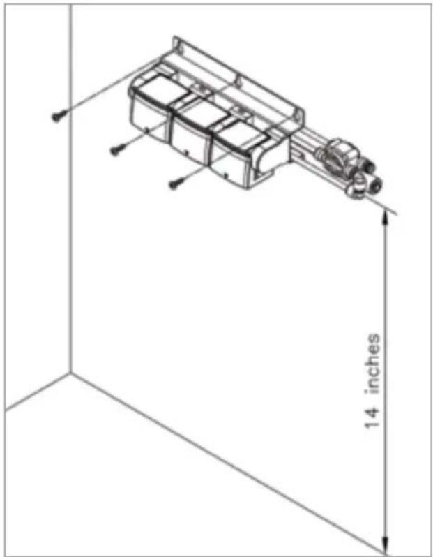
Be sure to install the Filter Head Connection Assembly so that the top of the assembly is at least 14 inches from the floor of the sink cabinet. Otherwise, the filters will not install correctly.
- Using a pencil, mark where the Filter Head Connection Assembly will be mounted to the sidewall of the cabinet (at least 14 inches from the cabinet floor). Use a level to make sure that the Assembly will be mounted straight.
NOTE: Before you mount the Connection Assembly, it may be a good idea to practice inserting and removing the filters.
- Insert the two mounting screws through the holes in the Assembly frame, and screw into the cabinet sidewall.
natural_image
Technical line drawing of a mechanical assembly with 14-inch dimension标注 (no text or symbols on the diagram itself)Step 2
Step 5: Filter Installation
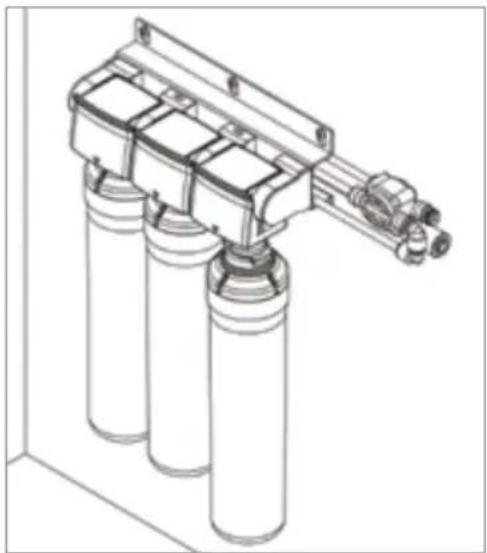
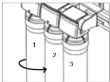
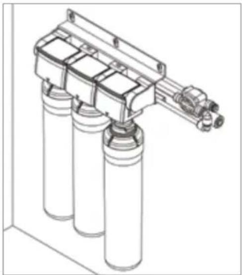
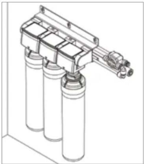
- It is very important to install the filters in the correct order. Match the same color label on each filter to the color label on the Filter Head Connection from left to right:
1) Activated Carbon Plus Filter
2) E2RO Membrane Filter
3) Carbon Block Filter
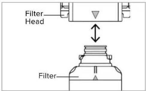
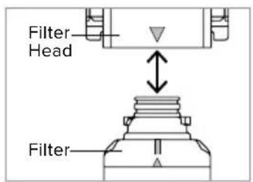
- To insert the filters, line up the arrow on the filter head with the arrow on the filter.
- With the top and bottom arrows lined up, push the top of the filter into the housing and turn to the right until the filter will not turn any more. The filter head arrow should now be lined up with the "circle" icon and notch on the top of the filter.
- Repeat the process for the E2RO Membrane and Carbon Block filters.
text_image
Filter Head FilterStep 2

natural_image
Technical line drawing of a mechanical assembly with a cylindrical component and multi-wire components (no text or symbols)Step 3
natural_image
Technical line drawing of a mechanical device with three cylindrical components and a multi-junction assembly (no text or symbols)Step 4
Step 6: Water Storage Tank Prep/Using "Quick Connectors"

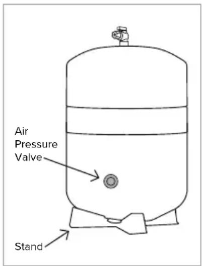
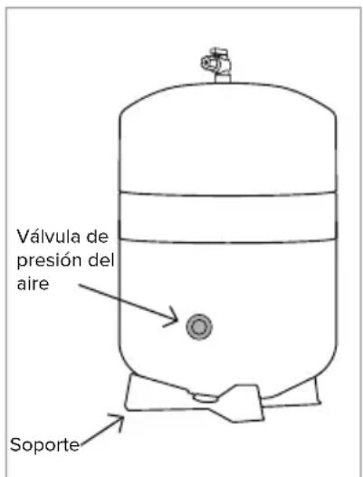
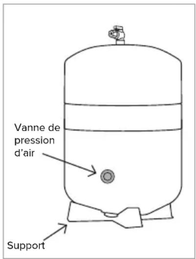
WARNING: DO NOT tamper with the air valve cap on the front of the water storage tank. It has been preset at 6psi.
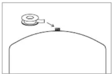
- Apply Teflon tape around the threaded outlet on top of the water storage tank.
- Screw the Tank Ball Valve tightly to the top of the tank.
- Place the tank on the tank stand with the valve upright, and position it underneath the sink next to the system assembly.
natural_image
Simple line drawing of a mechanical component with a lever and base, no text or symbols presentStep 1
text_image
Air Pressure Valve StandStep 2 Step 3

WARNING: DO NOT hold the ball valve to lift or carry the tank. Personal injury or property damage may result if the valve breaks off.
Using "Quick Connectors"
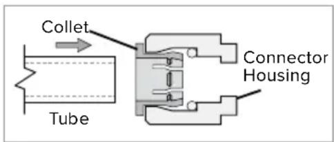
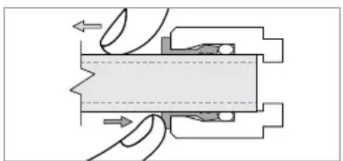
Tube connections on the T-valve, Filter Head Connection Assembly, and Indicator Faucet are all of the “Quick Connect” variety. The steps below illustrate how to connect and disconnect the tubes from these connectors.
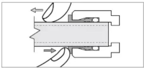
a. Push the tube into the Collet. The collet is a collar that provides a secure fit for the Tube and prevents water leaks.
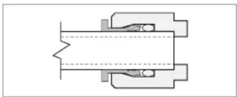
b. Push the tube in until it stops. The tube will be secure and resistant to tugs or pulls. The collet will be rigid and raised slightly from the Connector Housing.
c. To disconnect the tube, push down and hold the collet first, and then pull the tube out gently.
NOTE: Visit brondell.com for our Quick Connect Tutorial Video.
text_image
Collet Tube Connector HousingStep a
natural_image
Pure mechanical cross-section diagram without any text, numbers, or symbolsStep b
natural_image
Pure mechanical cross-section diagram without any text, numbers, or symbolsStep c
Step 7: Connecting the Tube
1. Water Supply Connection
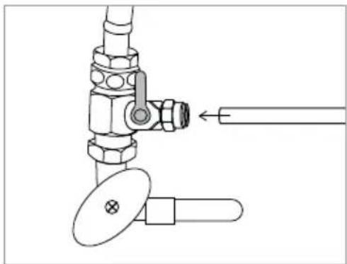
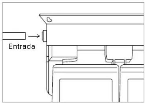
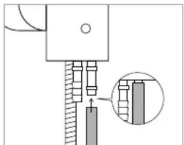
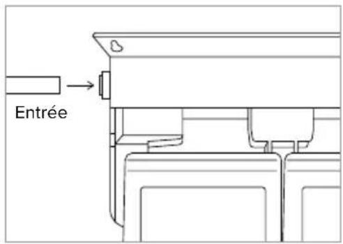
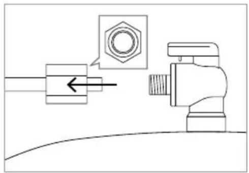
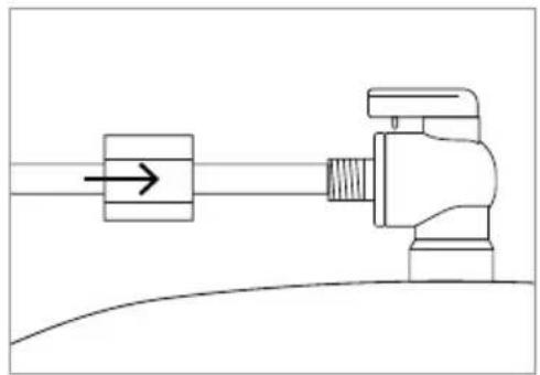
a. Measure the distance from your T-valve to where you have installed the filter head assembly, and cut the white, Water Supply Tubing. Insert one end of the tubing firmly into the Quick Connect fitting on the open side of the T-valve. Be sure to push in all the way, and ensure the tubing is not bent or kinked.
TIP: When cutting the Water Supply Tubing, use sharp scissors or a cutting knife for a clean cut. The opening edge of the tube should be even and clean. If the opening is frayed or crimped, this may affect the flow of the water running through the tube.
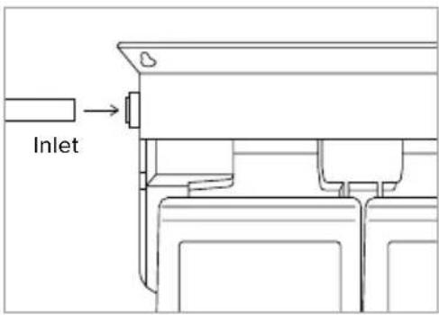
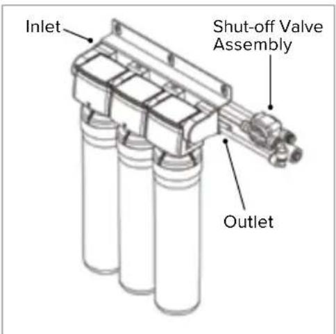
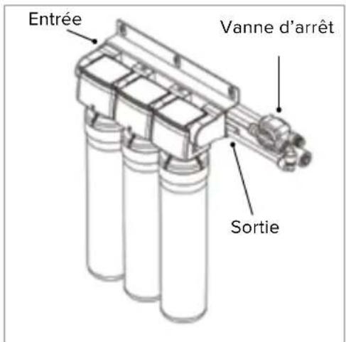
b. Connect the opposite end of the white Water Supply Tubing into the 90° Quick Connect elbow labeled "Inlet" located on the left side of the Filter Head Connector Assembly.
2. Faucet Connection
Connect the open end of the Blue Tubing from the Faucet to the Filter Head Connector Assembly "Outlet" by inserting the Tube into the Quick Connect on the right side. Be sure to push in all the way, and ensure the tubing is not bent or kinked.
3. Brine Input to Flow Restrictor Connection
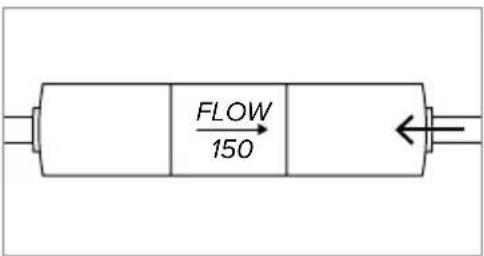
Take the opposite end of the 1/4" orange brine input tube from the faucet, and firmly insert into the Quick Connect on the Flow Restrictor. Be sure to push in all the way and ensure the tubing is not bent or kinked.
natural_image
Technical line drawing of a mechanical valve assembly with a shaft and flange (no text or symbols)Step 1a
text_image
InletStep 1b
text_image
Inlet Shut-off Valve Assembly OutletStep 2
text_image
FLOW 150Step 3
Step 7: Connecting the Tube
4. Tank Connection
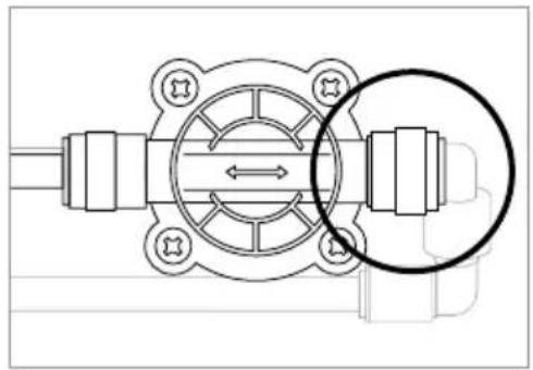
a. Measure out the white Water Supply Tubing, and carefully cut a piece for connecting the tank. Locate the Shut-off Valve Assembly. Insert one end of the tubing firmly into the Quick Connect on the assembly. Be sure to push in all the way, and ensure the tubing is not bent or kinked.
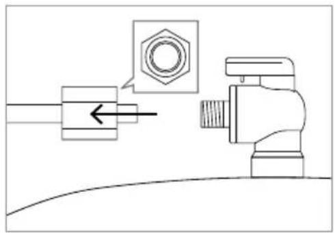
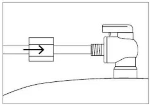
b. Unscrew the side cap from the Tank Ball Valve located on top of the tank. Take the cap and firmly slide the opposite end of the white tube through the cap.
c. Firmly insert the tube into the Tank Ball Valve. Slide the cap over the valve, and securely tighten into place.
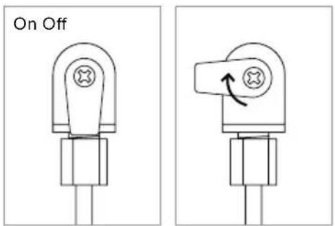
- Position the blue valve in the OFF position facing left.
natural_image
Technical diagram of a mechanical valve assembly with a highlighted circular component (no text or symbols)Step 4a
natural_image
Technical diagram showing a mechanical assembly with a nut and valve, no text or symbols presentStep 4b
natural_image
Pure mechanical diagram showing a lever and pivot point without any text, numbers, or symbolsStep 4c
text_image
On OffStep 5
Checking for Leaks/Flushing the System
Turn on Water & Check for Leaks
NOTE: Before turning the cold water on, review the installation instructions to ensure that the T-valve and water hoses are connected correctly and securely.
- Turn on water supply
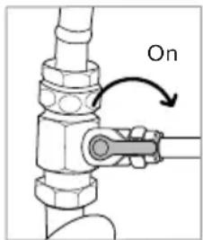
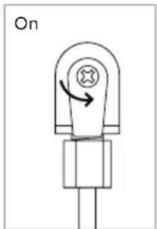
a. Open the T-valve by turning the valve arm 90° as shown.
b. Turn the cold-water supply valve at the wall counterclockwise to turn on. The cold-water supply will then begin to supply water to the Capella.
- Checking for leaks
a. Once the water supply has been turned on, check for any signs of leaking throughout the system.
b. If no leaks are found, wait 5 minutes and check one more time. If there is still no leaking, then continue to next step to flush the system.
NOTE: Failure to properly install this product or to properly check for leaks may cause damage to the property. In these instances, Brondell, Inc. will not be held responsible for any damages.
text_image
OnStep 1
Flushing The System
- Turn on the blue tank shut-off valve so that it is lined up in the same direction of the tank tubing.
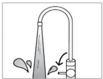
- Turn the provided faucet on all the way for 10 minutes to purge all the air out of the system. It is normal for some water to flow out of the faucet during this first purge.
- After the initial 10-minute purge, turn the provided faucet off and let the system run for 90 minutes to allow the water tank to fill for the first time.
NOTE: Depending on water temperature and incoming water pressure, it may take a shorter or longer period of time for the tank to fill.
text_image
OnStep 1
-
When the tank is full, turn the faucet on all the way once more for 10 minutes (or until the tank empties) to flush the filters and the water tank.
-
Turn the faucet off.
-
Repeat steps 3 and 4 and flush the system 2 more times (total 3 flushes). After the last flush, allow the tank to refill, and then filtered water will be ready to drink.
-
Record installation date on the Filter Change Chart on page 21 or on the provided sticker. For convenience, you may place the sticker under the sink or in another accessible place.
NOTE: Do not drink the water from the system until you have completed flushing the system.
Water Pressure
Traditional RO systems run on water pressure. Your incoming water pressure has a direct effect on how well your RO system will perform. With sufficient water pressure (max 100 psi), your RO system will function well and fill up the storage tank quickly.
To test your water pressure, you can use a water pressure gauge from your hardware store that connects onto your sink or garden faucet. Turn on the water all the way to FULL, and take a reading. Some areas may have different water pressure during the day and night. To get an accurate measurement, take several measurements at different times of the day and average them out.
If the tank takes too long to fill up, you may have insufficient water pressure (below 35 psi) and may need to add a pump to increase your water pressure. The type of booster pump that you may need will vary depending upon your specific usage and situation.
Non-standard installation (external booster pump or diverting water to a secondary outlet) may reduce the filter life or impact the system's operation.
Filters/Filter Change Indicators
Filters
The filters are critical to the performance of the Capella, and it is important to replace all of the filters on a regular basis. If any of the filters are overused beyond the recommended service life, the performance of the water filtration device can deteriorate. Do not miss the filter replacement cycle or use non-compatible filters as this can affect system performance or damage the unit.
NOTE: Contact Brondell at 888-542-3355, or visit us at www.brondell.com to order replacement filters.
Filter Change Indicator
The LED filter change indicator in the faucet works by tracking both time and water flow from the Capella.
When the faucet LED indicator begins to flash red, it's now time to change the filters and reset the faucet indicator by replacing the battery. A new battery is always included with the Capella RF-30 filter replacement set.
Filter Replacement
After replacing the filters, write down the date and filters changed on this Filter Change Chart (a separate sticker is also provided). It's important to track each filter change as the Activated Carbon Plus and Carbon Block Filters are on a more frequent cycle than the E2RO Membrane Filter. A replacement faucet battery is also included with the RF-30 filters.
| Filters to Change | Total Time Date Changed | ||
| Change 16 Months | Activated Carbon PlusCarbon Block | 6 Months | / / |
| Change 26 Months | Activated Carbon PlusCarbon Block | 12 Months | / / |
| Change 36 Months | Activated Carbon PlusCarbon Block | 18 Months | / / |
| Change 46 Months | Activated Carbon PlusCarbon BlockE2RO Membrane | 24 Months | / / |
-
Close the T-valve under the sink to shut off the flow of water to the Capella.
-
Once the T-valve is shut off, turn the Indicator Faucet on all the way and keep it on until the water tank is emptied and the pressure is released in the system. This should take about ten minutes, and the stream of water will slow to a stop when the tank has emptied. Turn the faucet off.
-
Remove each filter by turning to the left until the filter comes out of the Filter Head Connection Assembly.
-
Install the new filters by following the procedure below.
NOTE: It is very important to install the filters in the correct order.
Match the same label colors to the filter head labels, from left to right:
1) Activated Carbon Plus Filter
2) E2RO Membrane Filter
3) Carbon Block Filter
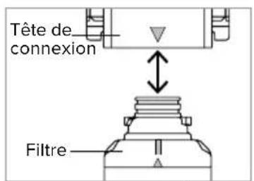
a. To insert the filters, first lineup the arrow on the filter heads with the arrow on the filters.

natural_image
Technical diagram of a pipe fitting with a valve and connecting rod (no text or labels)Step 1
natural_image
Illustration of a showerhead with water spray and pipe, no text or symbols presentStep 2
text_image
Filter Head FilterStep 4a
Filter Replacement
b. With the top and bottom arrows still lined up, insert the top of the filters into the housing and turn to the right until the filters will not turn anymore.
-
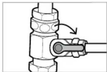
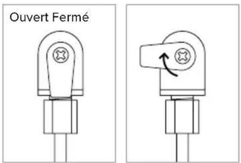
Open the T-valve to restore the flow of water to the Capella.
-
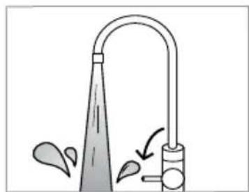
Flush the new filters and the system thoroughly with the following steps.
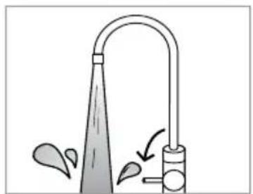
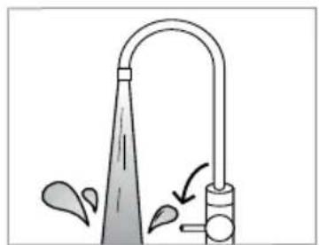
a. Turn the faucet on all the way for 10 minutes to purge all the air out of the system. It is normal for some water to flow out of the faucet during this first purge.
b. After the initial 10-minute purge, turn the faucet off and let the system run for 90 minutes or until the tank fills.
c. After 90 minutes, turn the faucet on all the way once more for 10 minutes (or until the tank empties) to flush the filters and the water tank.
d. Turn the faucet off.
e. The tank will fill again in about 90 minutes, and then filtered water will be ready to drink.
f. Record installation date on the filter change sticker chart, and place behind the sink cabinet door or another accessible place.
Battery Replacement For LED Indicator Faucet
- Replace the battery in the faucet LED indicator to reset the filter change reminder. The battery type is CR2032, and Brondell provides one with every set of RF-30 filters.
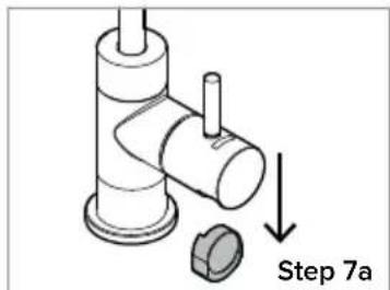
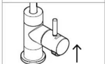
a. Under the faucet handle, locate the black rubber battery compartment. Grasp it from the sides, and pull down as shown.
b. Remove the old battery from the compartment by lifting the silver metal tab and sliding the battery out of the rubber casing. Wait 30 seconds for the residual energy to drain to reset the indicator.
c. Replace with a new CR2032 battery by sliding the battery under the silver tab, making sure that the words on the battery are facing out.
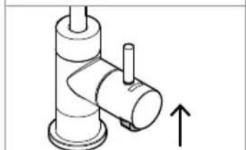
d. Push the black rubber battery compartment back up into the faucet handle.
e. The indicator will blink red once then blue once, then it will function as normal.
For California Residents: CR2032 batteries contain Perchlorate
Material — special handling may apply.
Visit www.dtsc.ca.gov/hazardouswaste/perchlorate for more information.
text_image
1 2 3Step 4b
natural_image
Mechanical component diagram showing a valve assembly with a rotating arrow (no text or symbols)Step 5
natural_image
Simple line drawing of a faucet with water spray and pipe (no text or symbols)Step 6a
text_image
Step 7a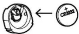
Step 7c
natural_image
Technical line drawing of a mechanical component with an upward arrow indicating motion (no text or symbols)Step 7d
MAINTENANCE
Extended Non-Use
If the system has not been used for two weeks or more, turn on the indicator faucet and allow the system to drain completely (about 10 minutes). After the system is drained, turn off the indicator faucet and allow the system to regenerate the water supply (about 90 minutes).
If the system will not be used for more than 45 days, close the T-valve under the sink to shut off the flow of water to the system. Turn on the indicator faucet, and allow the system to drain completely and the pressure to be released (about 10 minutes). Turn the faucet off.
When you are ready to use the system again, follow the instructions for “Flushing the System” on page 18.
H2O+ CAPELLA REVERSE OSMOSIS WATER FILTRATION SYSTEM
| Model | RC250 |
| Filters | Activated Carbon Plus, ER20 Membrane, Carbon Block |
| Product Dimensions | Assembled Filters & Hanger13.5"L x 3.75"W x 13.5"H (34.3 L x 9.5 W x 34.3 H cm)Tank with Stand14.5"H x 8.5"D (36.8 H x 21.6 D cm) |
| Net Weight | 11.4 lbs. (5.2 kg) |
WATER STORAGE TANK SPECIFICATIONS
| Product Dimensions | Tank with Stand14.5"H x 8.5"D(36.8 H x 21.6 D cm) |
| Volume | 3.2 gallons |
| Maximum Operating Pressure | 100 psi |
| Maximum Operating Temperature | 104°F (40°C) |
| Tank Pre-Charge | 6 psi |
| Diaphragm Material | Butyl Rubber |
| Construction Material | Stainless Steel |
WATER STORAGE TANK WARNINGS:
- Do not use the tank for any applications other than its intended use as this might cause failure or physical injury.
- Never exceed the maximum operating temperature of 104^ (40°C).
- Prior to any installation, re-installation, or work being performed on the tank or on the system, make sure that the tank is disconnected from the system and no water is able to leak.
- The air chamber of the tank contains compressed air.
- If the pressure tank leaks or shows signs of corrosion or damage, stop use and contact Brondell Customer Service.
The Capella RC250 RO system has been tested and certified by the Water Quality Association according to NSF/ANSI 42, 53, 58, and 401 for the reduction of Aesthetic Chlorine, Aesthetic Chloramine, Taste and Odor, Nominal Particulate Class 1, Cyst, VOCs, Asbestos, Mercury, Methyl Tert-Butyl Ether (MTBE), Turbidity, PFOA/PFOS, Fluoride, Pentavalent Arsenic, Barium, Radium 226/228, Cadmium, Hexavalent Chromium, Trivalent Chromium, Lead, Copper, Selenium, TDS, Atenolol, Bisphenol A, Carbamazepine, DEET, Estrone, Ibuprofen, Linuron, Meprobamate, Metolachlor, Naproxen, Nonyl Phenol, Phenytoin, TCEP, TCPP, Trimethoprim, and Microplastics as verified and substantiated by test data.
The system has been tested according to NSF/ANSI 42, 53, 58, and 401 for the reduction of the substances listed below. The concentration of the indicated substances in water entering the system was reduced to a concentration less than or equal to the permissible limit for water leaving the system, as specified in NSF/ANSI 42, 53, 58 and 401. The system has also been tested and certified by WQA according to NSF/ANSI/CAN 372 and CSA B483.1.
| Substance | Average Percent Reduction | Influent Challenge Concentration (Mg/L Unless Specified) | Maximum Permissible Product Water Concentration or Minimum Allowable % Reduction (mg/L unless specified) | |
| NSF/ANSI 42 Aesthetic Effects | Chlorine, Taste, & Odor 98.0% 2.00 ± 10% ≥ 50% Reduction | |||
| Chloramine 98.6% 3.00 ± 10% 0.5 | ||||
| Particulate Class 1 particles 0.5 to < 1 μm | 99.5% minimum 10,000 particles/mL | ≥ 85% Reduction | ||
| NSF/ANSI 53 Health Effects | Cyst 99.9% minimum 50,000 | particles/mL | ≥ 99.95% Reduction | |
| Mercury Reduction pH 8.5 93.3% 0.006 ± 10% 0.002 | ||||
| Mercury Reduction pH 6.5 96.9% 0.006 ± 10% 0.002 | ||||
| Lead Reduction pH 8.5 | 99.2% | 0.15 ± 10% | 0.005 | |
| Lead Reduction pH 6.5 | 99.7% | 0.15 ± 10% | 0.005 | |
| MTBE Reduction | 96.9% | 0.015 ± 10% | 0.005 | |
| Turbidity | 96.6% | 11 ± 1 NTU | 0.5 NTU | |
| VOC Surrogate Test | 99.8% | 3.00 ± 10% | ≥ 95% Reduction | |
| Asbestos Reduction | 99.96% | 100 - 1,000 MFL | ≥ 99% Reduction | |
| PFOA / PFOS Reduction | 99.0% | 0.0015 ± 10% | 0.00007 | |
| NSF/ANSI 58 Health Effects | Cadmium | 96.5% | 0.03 ± 10% | 0.005 |
| Trivalent Chromium III | 99.5% | 0.3 ± 10% | 0.1 | |
| Lead Reduction | 99.9% | 0.15 ± 10% | 0.005 | |
| Hexavient Chromium VI | 98.5% | 0.3 ± 10% | 0.1 | |
| Selenium Reduction | 98.5% | 0.10 ± 10% | 0.05 | |
| Copper Reduction | 99.2% | 3.0 ± 10% | 1.3 | |
| Arsenic | 99.1% | 0.30 ± 10% | 0.01 | |
| TDS Reduction | 96.4% | 750 ± 40 mg/L | 187 | |
| Radium 226/228 Reduction | 100.0% | 25 pCi/L ± 10% | 5 pCi/L | |
| Barium Reduction | 100.0% | 10 ± 10% | 2.0 | |
| Fluoride Reduction | 97.8% | 8.0 ± 10% | 1.5 | |
| NSF/ANSI 401 Emerging Contaminants | Bispherol A (BPA) | 95.0% | 2,000 ± 20% | 300 ng/L |
| Estrone | 96.0% | 140 ± 20% | 20 ng/L | |
| Ibuprofen | 95.0% 400 ± 20% 60 ng/L | |||
| Naproxen | 96.0% | 140 ± 20% | 20 ng/L | |
| Nonylphenol | 93.0% | 1,400 ± 20% | 200 ng/L | |
| Atenolol | 95.0% | 200 ± 20% | 30 ng/L | |
| NSF/ANSI 401 Emerging Contaminants | Carbamazepine | 97.0% | 1,400 ± 20% | 200 ng/L |
| Linuron 93.0% 140 ± 20% 20 ng/L | ||||
| Meprobamate | 95.0% | 400 ± 20% | 60 ng/L | |
| Phenytoin 95.0% 200 ± 20% 30 ng/L | ||||
| Trimethoprim | 96.0% | 140 ± 20% | 20 ng/L | |
| DEET 99.0% 1,400 ± 20% 200 ng/L | ||||
| Metolachlor | 100.0% | 1,400 ± 20% | 200 ng/L | |
| TCEP | 100.0% | 5,000 ± 20% | 700 ng/L | |
| TCPP | 100.0% | 5,000 ± 20% | 700 ng/L | |
| Microplastics | 99.5% | minimum 10,000 particles/mL | ≥ 85% Reduction | |
While testing was performed under laboratory conditions, actual performance may vary.
GENERAL OPERATING INFORMATION
| Rated Capacity | 300 gallons (1135.6 L) |
| Min-Max Operating Pressure | 35 - 100 psi(241 kPa – 689 kPa) |
| Min-Max Feed Water Temperature | 39°F – 100°F (4°- 38°C) |
| Rated Service Flow | 0.5 gpm (1.89 lpm) |
| Daily Water Production Rate | 21.9 gpd (82.9 lpd) |
| Product Efficiency Rating | 29.1% |
- Do not use with water that is microbiologically unsafe or of unknown quality without adequate disinfection before or after the system.
- Refer to the owners manual for specific installation instructions, manufacturer's limited warranty, user responsibility, and parts and service availability.
- The influent water to the system shall include the following characteristics:
- Systems certified for cyst reduction may be used on disinfected waters that may contain filterable cysts.
• No organic solvents
(5 - 35°C)
• Chlorine: < 2 mg/L
- Iron: < 2 mg/L
- pH: 7 - 8
• Turbidity: < 1 NTU
• Temperature: 41 - 95°F
• Hardness: < 1,000 mg/L
• For parts and service availability, please contact Brondell at 888-542-3355.
- The compounds certified under NSF/ANSI 401 have been deemed as "incidental contaminants/emerging compounds". Incidental contaminants are those compounds that have been detected in drinking water supplies at trace levels. While occurring at only trace levels, these compounds can affect the public acceptance/perception of drinking water quality.
This system has been tested for the treatment of water containing pentavalent arsenic (also known as As(V), As(+5), or arsenate) at concentrations of 0.050 mg/L or less. This system reduces pentavalent arsenic, but may not remove other forms of arsenic. This system is to be used on water supplies containing a detectable free chlorine residual at the system inlet or on water supplies that have been demonstrated to contain only pentavalent arsenic. Treatment with chloramines (combined chlorine) is not sufficient to ensure complete conversion of trivalent arsenic to pentavalent arsenic. Please see the Arsenic Facts section of this Performance Data Sheet for further information.
Efficiency rating means the percentage of the influent water to the system that is available to the user as reverse osmosis treated water under operating conditions that approximate typical daily usage.
The product water should be tested every 6 months to ensure that the contaminants are being reduced effectively. For any questions, please contact Brondell toll free at 888-542-3355.
This reverse osmosis system contains replaceable treatment components, critical for the effective reduction of total dissolved solids and that product water shall be tested periodically to verify that the system is performing properly. Replacement of reverse osmosis component should be with one of identical specifications, as defined by the manufacturer, to assure the same efficiency and contaminant reduction performance.
The estimated replacement time of filter, which is a consumable part, is not an indication of quality guarantee period, but it means the ideal time of filter replacement. Accordingly, the estimated time of filter replacement may be shortened in case it is used in an area of poor water quality.
System and installation shall comply with all state and local regulations.
Filter Replacement Cycle
| Part Number Filter Name Usable Period | ||
| RF-30 | Activated Carbon Plus FilterCarbon Block Filter | 6 Months6 Months |
| RF-50 E2RO Membrane Filter 24 Months | ||
* The filter replacement cycle may be reduced for areas with poor water quality or greater use.
ARSENIC FACTS
Arsenic (abbreviated As) is found naturally in some well water. Arsenic in water has no color, taste, or odor. It must be measured by a laboratory test. Public water utilities must have their water tested for arsenic. You can get the results from your water utility. If you have your own well, you can have the water tested. The local health department or the state environmental health agency can provide a list of certified labs. The cost is typically \15 to \30. Information about arsenic in water can be found on the internet at the U.S. Environmental Protection Agency website: www.epa.gov/safewater/arsenic.html.
There are two forms of arsenic: pentavalent arsenic (also called As(V), As(+5), and arsenate) and trivalent arsenic (also called As(III), As(+3), and arsenite). In well water, arsenic may be pentavalent, trivalent, or a combination of both. Special sampling procedures are needed for a lab to determine what type and how much of each type of arsenic is in the water. Check with the labs in your area to see if they can provide this type of service.
Reverse osmosis (RO) water treatment systems do not remove trivalent arsenic from water very well. RO systems are very effective at removing pentavalent arsenic. A free chlorine residual will rapidly convert trivalent arsenic to pentavalent arsenic. Other water treatment chemicals such as ozone and potassium permanganate will also change trivalent arsenic to pentavalent arsenic. A combined chlorine residual (also called chloramine) may not convert all the trivalent arsenic. If you get your water from a public water utility, contact the utility to find out if free chlorine or combined chlorine is used in the water system.
The RC250 system is designed to remove pentavalent arsenic. It will not convert trivalent arsenic to pentavalent arsenic. The system was tested in a lab. Under testing conditions, the system reduced 0.30 mg/L (ppm) or 0.050 mg/L (ppm) pentavalent arsenic to 0.010 mg/L (ppm) (the USEPA standard for drinking water) or less. The performance of the system may be different at your installation. Have the treated water tested for arsenic to check whether the system is working properly.
The RO component of the RC250 system must be replaced every 24 months to ensure that the system will continue to remove pentavalent arsenic. The component identification and locations where you can purchase the component are listed in the installation/operation manual.
Volatile Organic Chemicals (VOCs) Included by Surrogate Testing*
| Chemical | Drinking Water Regulatory level ^1 (MCL/MAC) mg/L | Influent Challenge Concentration ^2 mg/L | Chemical Reduction Percent (%) | Maximum Product Water Concentration mg/L |
| alachlor 0.002 0.050 >98 0.001 | 3 | |||
| atrazine | 0.003 | 0.100 | >97 | 0.003 ^3 |
| benzene 0.005 0.081 >99 0.001 | 3 | |||
| carbofuran | 0.040 | 0.190 | >99 | 0.001 ^3 |
| carbon tetrachloride 0.005 0.078 98 0.0018 | 4 | |||
| chlorobenzene | 0.100 | 0.077 | >99 | 0.001 ^3 |
| chloropicrin | - | 0.015 | 99 | 0.0002 ^2 |
| 2,4-D | 0.070 | 0.110 | 98 | 0.0017 ^2 |
| dibromochloropropane(DBCP) | 0.0002 | 0.052 >99 0.00002 | 3 | |
| o-dichlorobenzene | 0.600 | 0.080 | >99 | 0.001 ^3 |
| p-dichlorobenzene | 0.075 | 0.040 | >98 | 0.001 ^3 |
| 1,2-dichloroethane | 0.005 0.088 95 | 5 | 0.0048 ^2 | |
| 1,1-dichloroethylene | 0.007 | 0.083 | >99 | 0.001 ^3 |
| cis-1,2-dichloroethylene | 0.070 | 0.170 | >99 | 0.0005 ^2 |
| trans-1,2-dichloroethylene | 0.100 | 0.086 | >99 | 0.001 ^3 |
| 1,2-dichloropropane | 0.005 | 0.080 | >99 | 0.001 ^3 |
| cis-1,3-dichloropropylene | - | 0.079 | >99 | 0.001 ^3 |
| dinoseb | 0.007 | 0.170 | 99 | 0.0002 ^2 |
| endrin | 0.002 0.053 99 0.00059 | 4 | ||
| ethylbenzene | 0.700 | 0.088 | >99 | 0.001 ^3 |
| ethylene dibromide (EDB) | 0.00005 | 0.044 | >99 | 0.00002 ^3 |
| haloacetonitriles (HAN) | ||||
| bromochloroacetonitrile | - | 0.022 | 98 | 0.0005 ^3 |
| dibromoacetonitrile | - | 0.024 | 98 | 0.0006 ^3 |
| dichloroacetonitrile | - | 0.0096 | 98 | 0.0002 ^2 |
| trichloroacetonitrile | - | 0.015 | 98 | 0.0003 ^3 |
| haloketones (HK): | ||||
| 1,1-dichloro-2-propanone | - | 0.0072 | 99 | 0.0001 ^3 |
| 1,1,1-trichloro-2-propanone | - | 0.0082 | 96 | 0.0003 ^3 |
| heptachlor | 0.0004 | 0.025 | >99 | 0.0001 ^3 |
| heptachlor epoxide | 0.0002 | 0.010 ^2 | 98 0.0002 | 6 |
| hexachlorobutadiene | - | 0.044 | >98 | 0.001 ^3 |
| hexachlorocyclopentadiene | 0.050 | 0.060 | >99 | 0.000002 ^3 |
| lindane | 0.0002 | 0.055 | >99 | 0.00001 ^3 |
| methoxychlor | 0.040 | 0.050 | >99 | 0.0001 ^3 |
| pentachlorophenol | 0.001 | 0.096 | >99 | 0.001 ^3 |
| simazine | 0.004 | 0.120 | >97 | 0.004 ^2 |
| styrene | 0.100 | 0.150 | >99 | 0.0005 ^3 |
| 1,1,2,2-tetrachloroethane | - | 0.081 | >99 | 0.001 ^3 |
| tetrachloroethylene | 0.005 | 0.081 | >99 | 0.001 ^3 |
| toluene | 1.000 | 0.078 | >99 | 0.001 ^3 |
| 2,4,5-TP (silvex) | 0.050 | 0.270 | 99 | 0.0016 ^4 |
| tribromoacetic acid | - | 0.042 | >98 | 0.001 ^3 |
| 1,2,4-trichlorobenzene | 0.070 | 0.160 | >99 | 0.0005 ^3 |
| 1,1,1-trichloroethane | 0.200 | 0.084 | 95 | 0.0046 ^4 |
| 1,1,2-trichloroethane | 0.005 | 0.150 | >99 | 0.0005 ^3 |
| trichloroethylene | 0.005 | 0.180 | >99 | 0.0010 ^3 |
| trihalomethanes (includes): | ||||
| chloroform (surrogate chemical) | ||||
| bromoform | ||||
| bromodichloromethane | 0.080 | 0.300 | 95 | 0.015 |
| chlorodibromomethane | ||||
| xylenes (total) | 10 | 0.070 | >99 | 0.001 ^3 |
* Chloroform was used as the surrogate chemical for VOC reduction claims.
-
These harmonized values were agreed upon by representatives of USEPA and Health Canada for the purpose of evaluating products to the requirements of this Standard.
-
Influent challenge levels are average influent concentrations determined in surrogate qualification testing.
-
Maximum product water level was not observed but was set at the detection limit of the analysis.
-
Maximum product water level is set as a value determined in surrogate qualification testing.
-
Chemical reduction percent and maximum product water level calculated at chloroform 95% break through point as determined in surrogate qualification testing.
-
The surrogate test results for heptachlor epoxide demonstrated a 98% reduction. These data were used to calculate an upper occurrence concentration which would produce a maximum product water level at the MCL.
If the Capella appears to be operating abnormally, please review the troubleshooting tips before calling the Brondell Service Center as most issues are easily resolved with a few simple steps. If you are unable to resolve the issue after checking the following items, please call the Service Center at 888-542-3355, Mon–Fri, 9am–5pm PST (English and Spanish spoken), or email us at support@brondell.com.
If the Capella experiences difficulties, close the T-valve to shut off the incoming water to the unit.
| Problem Possible Cause(s) Solution(s) | ||
| My TDS meter is not reading zero | It could be normal operation, or the filters may need to be changed | Generally, RO systems lower TDS readings by as much as 90% when compared to tap water readings. This is a normal working range. For example, if your tap water TDS reading is 100, then a normal TDS reading for the RO filtered water is in the range of 0–10. If the TDS reading for the RO filtered water is higher than 15% of normal tap water, this indicates it's time for a filter change (including RO membrane). |
| No water, not enough water, or low water flow | 1. Incoming water supply valve or T-valve is turned off | 1. Turn on incoming water supply valve or T-valve. |
| 2. Low incoming water pressure | 2. Verify pressure is above 35 psi; install a booster pump if needed. | |
| 3. Capacity is exhausted | 3. Allow time for the Capella to replenish the water storage tank. | |
| 4. Plumbing restriction | 4. Check connections and tubes for obstructions. | |
| 5. Other filter or RO membrane is clogged | 5. See Filter Replacement (page 21). | |
| 6. Tank shut-off valve is closed | 6. Ensure tank shut-off valve is in the open position and lined up in the same direction of the tank tubing. | |
| 7. System is starting up | 7. Normally it takes up to two hours to fill the water storage tank. Low incoming water pressure and/or temperature can also reduce production rate. | |
| 8. Check air pressure in water storage tank. | 8. Tank air pressure should be 5-7 psi when empty of water. If below 5 psi, add air, or release air if above 7 psi. Check only when the tank is empty of water. | |
| Unexpected flow in drain line | The auto shut-off valve is inoperative | See product warranty in last page of manual, and contact Brondell. |
| No drain flow 1. | Other filters or E2RO Membrane is clogged | 1. See Filter Replacement (page 21). |
| 2. The flow restrictor is inoperative | 2. See product warranty in last page of manual, and contact Brondell. | |
| Bad tasting water 1. Carbon Block Filter is exhausted | 1. See Filter Replacement (page 21). | |
| 2. Newly replaced Carbon Block Filter is not flushed completely | ||
| 3. E2RO Membrane filter is exhausted | ||
| 4. Water has been sitting in the tank for too long | ||
| Cloudy water Dissolved air in incoming water supply | Problem should clear up as the condition of the incoming water changes. Letting water stand will allow the dissolved air to dissipate. | |
| Leaking water from the Capella | Tube is not fully inserted into a connection | Make sure the tube is at least 12 -inch into the connection. |
| Filter is not installed correctly | Ensure that all three filters are locked into place. | |
| The tip of the tube is damaged | Cut the damaged part of the tube, and reconnect or replace the tube. | |
Brondell products are backed by some of the most comprehensive warranties in the industry. Brondell warrants that the H2O+ water filtration system shall be free from defects in material and workmanship under normal use and service.
Brondell H2O+ Capella
One Year Warranty 100% Coverage of all parts and labor for the entire product for the first year from original date of purchase. This does not apply, however, to consumable filters.
Exclusions and Limitations
- BRONDELL warrants its products to be free from manufacturing defects under normal use and service. This warranty is extended only to the ORIGINAL PURCHASER.
- BRONDELL's obligations under this warranty are limited to repairs or replacement, at BRONDELL's option, of products or parts found to be defective, provided that such products were properly installed and used in accordance with instructions. BRONDELL reserves the right to make such inspections as may be necessary in order to determine the cause of the defect. BRONDELL will not charge for labor or parts in connection with warranty repairs for the first full year from date of purchase on all products except those that may be subject to commercial use limitations.
- BRONDELL is not responsible for the cost of removal, return (shipping), and/or reinstallation of products. This warranty does NOT apply to:
- Damage or loss that occurs during shipment.
- Damage or loss sustained through any natural or man-made causes beyond the control of BRONDELL, including but not limited to fire, earthquake, floods, etc.
- Damage or loss resulting from sediments or foreign matter contained in a water system.
- Damage or loss resulting from negligent or improper installation including installation of a unit in a harsh or hazardous environment.
- Damage or loss resulting from removal, improper repair, modification of the product, or improper maintenance including damage caused by chlorine or chlorine related products.
-
Damage or loss resulting from acts that are not the fault of Brondell or that the Product is not specified to tolerate.
-
This warranty gives you specific legal rights. You may have other rights, which vary from state to state.
THIS WRITTEN WARRANTY IS THE ONLY WARRANTY MADE BY BRONDELL. REPAIR OR REPLACEMENT AS PROVIDED UNDER THIS WARRANTY SHALL BE THE EXCLUSIVE REMEDY AVAILABLE TO THE PURCHASER. BRONDELL SHALL NOT BE RESPONSIBLE FOR LOSS OF USE OF THE PRODUCT OR FOR OTHER INCIDENTAL, SPECIAL, OR CONSEQUENTIAL DAMAGES OR EXPENSES INCURRED BY THE PURCHASER OR FOR LABOR OR OTHER COSTS DUE TO INSTALLATION OR REMOVAL OR COSTS OF REPAIRS BY OTHERS, OR FOR ANY OTHER EXPENSE NOT SPECIFICALLY STATED ABOVE. EXCEPT TO THE EXTENT PROHIBITED BY APPLICABLE LAW, ANY IMPLIED WARRANTIES, INCLUDING THAT OF MERCHANTABILITY, ARE EXPRESSLY LIMITED TO THE DURATION OF THIS WARRANTY. SOME STATES DO NOT ALLOW LIMITATIONS, SO THE ABOVE LIMITATION AND EXCLUSION MAY NOT APPLY TO YOU.
How to Obtain Service
To obtain repair service under this warranty, you must contact an authorized BRONDELL Service Center to obtain an RMA (Return Merchandise Authorization) number. Proof of purchase in the form of a copy of the original receipt must accompany the returned unit for the warranty to be valid. Take or ship the unit prepaid to the closest Brondell authorized service center along with the RMA number and proof of purchase. To obtain the RMA number and locate the BRONDELL Service Center location nearest you, please call 1-888-542-3355.
brondell®
a healthy home experience
CONTACT:
Brondell, Inc.
PO Box 470085
San Francisco, CA 94147-0085
Phone: 1-888-542-3355
Email: support@brondell.com
Web: www.brondell.com
For questions, contact Brondell
Customer Service:
1-888-542-3355, Monday – Friday,
9am – 5pm PST
MANUFACTURED BY:
Brondell, Inc.
PO Box 470085
San Francisco, CA 94147-0085
Made in Korea
REPLACEMENT FILTERS:
RF-30 Two-Filter Set,
Activated Carbon Plus and
Carbon Block Filter
RF-50 E2RO Membrane Filter
Please retain receipt records for any warranty claims.
natural_image
Line drawing of a water treatment tank with multiple pressure vessels and piping (no text or symbols)natural_image
Diagram of a mechanical or electrical component with three pipes and a central valve (no text or symbols)Paso1
natural_image
Technical line drawing of a mechanical assembly with pipes and a valve (no text or symbols)Paso 3
natural_image
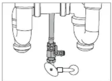
Technical line drawing of a mechanical valve assembly with three pipes and a handle (no text or symbols)Paso 4
natural_image
Two identical illustrations of a showerhead with adjustable tubing and a valve, shown in side and top views (no text or symbols)Paso 1
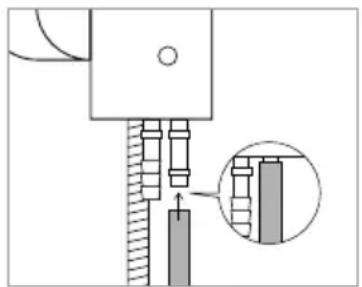
natural_image
Pure mechanical assembly diagram without any text, numbers, or symbolsPaso 3
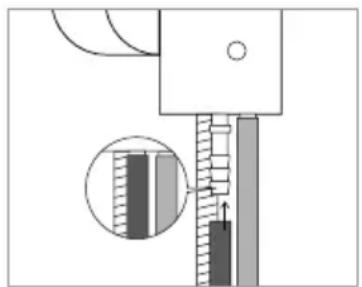
natural_image
Mechanical assembly diagram showing a piston and shaft with a magnified inset of internal components (no text or symbols)Paso 4
natural_image
Mechanical assembly diagram showing a piston and connecting rod assembly (no text or labels)Paso 5
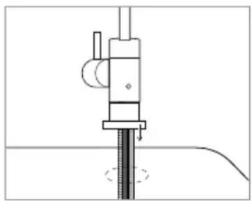
natural_image
Pure mechanical assembly diagram without any text, numbers, or symbolsPaso 6
natural_image
Technical diagram showing a mechanical assembly with a rotating component and a magnified inset (no text or symbols)Paso 7
natural_image
Pure technical line drawing of a mechanical component with no text or symbolsPaso 8
natural_image
Mechanical assembly diagram showing a bolt and nut assembly with an inset close-up of the component (no text or labels)Paso 9
natural_image
Technical line drawing of a drill bit with a tool and screw head (no text or symbols)Paso 2
natural_image
Mechanical clamp assembly diagram with threaded pins and central shaft (no text or labels)Paso 3a
natural_image
Technical line drawing of a mechanical clamp or bracket assembly (no text or symbols)Paso 3b
natural_image
Technical line drawing of a mechanical clamp or bracket assembly (no text or symbols)Paso 4
natural_image
Technical line drawing of a mechanical assembly with dimension annotation (35 cm) and no readable text or symbolsPaso 2
natural_image
Technical line drawing of a mechanical assembly with a cylindrical component and multi-wire components (no text or symbols)Paso 3
natural_image
Technical line drawing of a mechanical device with three cylindrical components and a multi-tiered arm (no text or symbols)Paso 4
natural_image
Simple line drawing of a container with a spool and a small object on top, no text or symbols present.Paso 1
natural_image
Pure mechanical cross-section diagram without any text, numbers, or symbolsPaso b
natural_image
Pure mechanical diagram showing a piston-cylinder assembly with no text, numbers, or symbolsPaso c
natural_image
Technical line drawing of a mechanical valve assembly with a shaft and adjustment knob (no text or symbols)Paso 1a
text_image
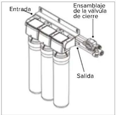
EntradaPaso 1b
natural_image
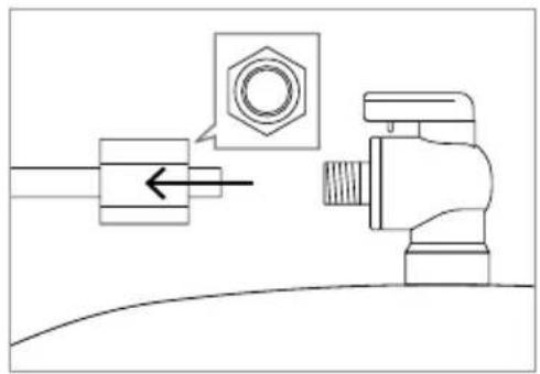
Technical diagram of a mechanical valve assembly with a highlighted circular component (no text or symbols)Paso 4a
natural_image
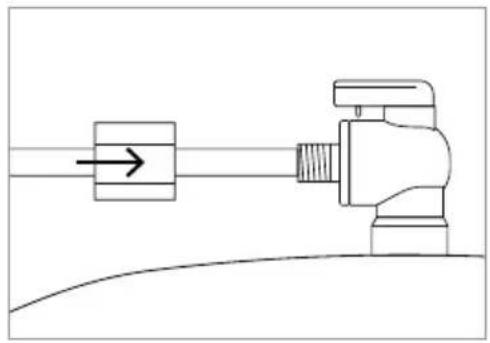
Technical diagram showing a mechanical assembly with a nut and valve, no text or symbols presentPaso 4b
natural_image
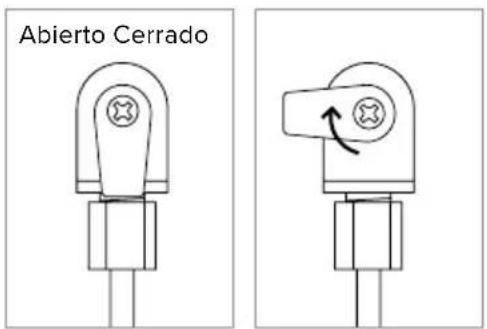
Pure mechanical diagram showing a lever and pivot point without any text, numbers, or symbolsPaso 4c
natural_image
Technical diagram of a pipe fitting with a valve mechanism (no text or labels)Paso 1
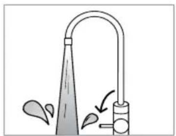
natural_image
Illustration of a showerhead with water spray and pipe, showing fluid flow (no text or symbols)Paso 2
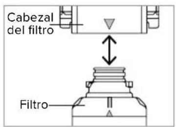
text_image
Cabezal del filtro FiltroPaso 4a
natural_image
Mechanical component diagram showing a valve assembly with a rotating arrow (no text or symbols)Paso 5
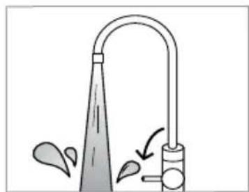
natural_image
Simple line drawing of a faucet with water spray and pipe (no text or symbols)Paso 6a
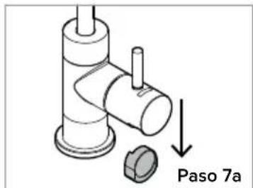
text_image
Paso 7a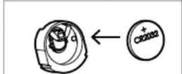
text_image
CR20S2Paso 7c
natural_image
Technical diagram of a mechanical component with an upward arrow indicating motion (no text or symbols present)Paso 7d
MANTENIMIENTO
Desuso prolongado
trihalomethanes (includes):
| cloroformo (producto químicosustitutivo) bromoformobromodiclorometanoclorodibromometano | 0.080 | 0.300 | 95 | 0.015 |
| xilenos (total) | 10 | 0.070 | >99 | 0.001^3 |
a healthy home experience
CONTACTO:
Brondell, Inc.
PO Box 470085
San Francisco, CA 94147-0085
natural_image
Line drawing of a water treatment tank with multiple pressure vessels and piping (no text or symbols)Table des matières
INSTALLATION DU PRODUIT
natural_image
Diagram of a mechanical valve assembly with two pipes and a central hub (no text or labels)Étape 1

natural_image
Technical line drawing of a mechanical assembly with pipes and a valve (no text or symbols)Étape 3
natural_image
Technical line drawing of a mechanical valve assembly with three pipes and a handle (no text or symbols)Étape 4
natural_image
Two identical hand-painted illustrations of a shower faucet with no text or symbolsÉtape 1
natural_image
Mechanical assembly diagram showing a shaft and housing with a magnified inset of a component detail (no text or symbols)Étape 3
natural_image
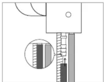
Mechanical assembly diagram showing a piston and shaft with a magnified inset of internal components (no text or symbols)Étape 4
natural_image
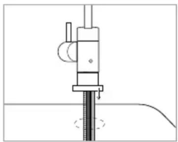
Mechanical assembly diagram showing a piston and shaft assembly (no text or labels)Étape 5
natural_image
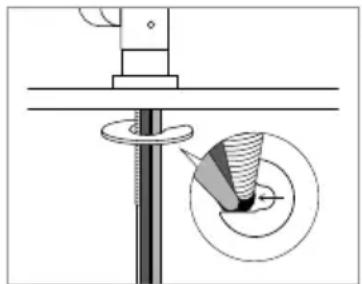
Pure mechanical assembly diagram without any text, numbers, or symbolsÉtape 6
natural_image
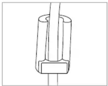
Technical diagram showing a mechanical assembly with a rotating shaft and circular component, no visible text or symbolsÉtape 7
natural_image
Pure technical line drawing of a mechanical component with no text or symbolsÉtape 8
natural_image
Mechanical assembly diagram showing a bolted joint with a magnified inset detail (no text or symbols)Étape 9
natural_image
Technical line drawing of a mechanical device emitting a pipe or wire (no text or symbols)Étape 2
natural_image
Mechanical clamp assembly diagram with threaded pins and central shaft (no text or labels)Étape 3a
INSTALLATION DU PRODUIT
natural_image
Technical line drawing of a mechanical clamp or bracket assembly (no text or symbols)Étape 3b
natural_image
Technical line drawing of a mechanical component with a shaft and curved housing (no text or symbols)Étape 4
natural_image
Technical line drawing of a mechanical assembly with dimension annotation (35 cm) and directional arrows, no readable text or symbols present.Étape 2
natural_image
Technical line drawing of a mechanical assembly with a cylindrical component and multi-wire components (no text or symbols)Étape 3
natural_image
Technical line drawing of a mechanical device with three cylindrical components and a multi-junction assembly (no text or symbols)Étape 4
natural_image
Simple line drawing of a mechanical component with a lever and base, no text or symbols presentÉtape 1
natural_image
Pure mechanical cross-section diagram without any text, numbers, or symbolsÉtape b

natural_image
Cross-sectional diagram of a mechanical assembly with internal components and fluid flow arrows (no text or labels)Étape c
natural_image
Technical line drawing of a mechanical valve assembly with a shaft and adjustment knob (no text or symbols)Étape 1a
text_image
EntréeÉtape 1b
natural_image
Technical diagram of a mechanical valve assembly with a highlighted circular component (no text or symbols)Étape 4a
natural_image
Technical diagram showing a mechanical assembly with a nut and valve, no text or symbols presentÉtape 4b
natural_image
Pure mechanical diagram showing a valve or actuator with a directional arrow, no text or symbols presentÉtape 4c
text_image
Ouvert FerméÉtape 5
natural_image
Diagram of a pipe fitting with a valve and connecting rod (no text or labels)Étape 1
natural_image
Simple line drawing of a faucet with water spray and valve (no text or symbols)Étape 2
text_image
Tête de connexion FiltreÉtape 4a
natural_image
Mechanical assembly diagram showing a valve with a rotating shaft (no text or symbols)Étape 5
natural_image
Simple line drawing of a showerhead with water spray and pipe (no text or symbols)Étape 6a
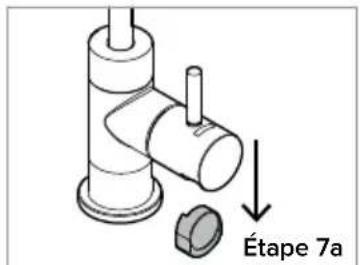
text_image
Étape 7a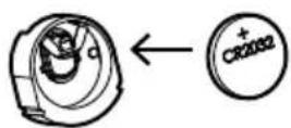
Étape 7c
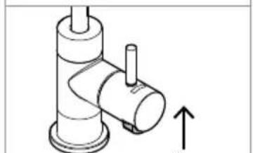
natural_image
Technical diagram of a mechanical component with an upward arrow indicating motion (no text or symbols)Étape 7d
ENTRETIEN
a healthy home experience
COORDONNÉES :
Brondell, Inc.
PO Box 470085
San Francisco, CA 94147-0085
Téléphone : 1-888-542-3355