Coral - Water filter Brondell - Free user manual and instructions
Find the device manual for free Coral Brondell in PDF.

| Product Type | Under-sink water filtration system |
| Model | Coral UC300 (3 stages) / UC100 (1 stage) |
| Brand | Brondell |
| Dimensions (UC300) | 9 in (W) x 13.5 in (H) x 3.75 in (D) |
| Dimensions (UC100) | 3.5 in (W) x 13.5 in (H) x 3.75 in (D) |
| Net weight (UC300) | 3.8 lb (1.72 kg) |
| Net weight (UC100) | 1.8 lb (0.82 kg) |
| Indicator faucet power | CR2032 battery (included) |
| Operating temperature | 4°C to 38°C (39°F to 100°F) |
| Operating pressure | 241 kPa to 689 kPa (35 psi to 100 psi) |
| Flow rate | 1.89 L/min (0.50 gpm) |
| Capacity UC300 | 600 gallons (2271 L) |
| Capacity UC100 | 300 gallons (1135 L) |
| UC300 filtration method | Sediment filter, carbon pre-filter, carbon block filter |
| UC100 filtration method | Carbon block filter |
| UC300 replacement filters | UF-35 set (sediment filter + carbon pre-filter + carbon block) |
| UC100 replacement filters | UF-15 set (carbon block filter) |
| UC300 filter lifespan | 12 months or 600 gallons |
| UC100 filter lifespan | 6 months or 300 gallons |
| Replacement indicator | LED on faucet: blue = OK, red = change filter |
| Installation | Quick connect, fits existing sinks (hole ≥ 17/40 in) |
| Certifications | WQA certified to NSF/ANSI 42, 53, 372 |
| Warranty | 1-year limited (parts and labor) |
| UC300 box contents | Filter head, 3 filters, LED faucet, T-valve, adapters, tubing, screws, 90° elbows, battery |
| UC100 box contents | Filter head, 1 filter, LED faucet, T-valve, adapters, tubing, screws, 90° elbows, battery |
Frequently Asked Questions - Coral Brondell
User questions about Coral Brondell
0 question about this device. Answer the ones you know or ask your own.
Ask a new question about this device
Download the instructions for your Water filter in PDF format for free! Find your manual Coral - Brondell and take your electronic device back in hand. On this page are published all the documents necessary for the use of your device. Coral by Brondell.
USER MANUAL Coral Brondell
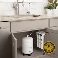
natural_image
Exterior view of a modern water treatment stand with three H2O+ units and a stainless steel faucet (no visible text or symbols on the main components)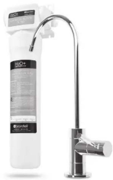
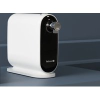
natural_image
Product photo of a Brondell water dispenser with a stainless steel faucet (no visible text or symbols on the device itself)
natural_image
Blank document page with a thin line at the top and a rounded corner frame (no text or symbols)CONTENTS
Read this Owner's Manual for correct installation, use and maintenance of this product. After reading and completing installation, keep this manual in a place that is easily accessible.
GENERAL INFO
02 SAFETY INFORMATION
03 TDS METER INFORMATION
04 FEATURES
05 UC 300 PRODUCT COMPONENTS
06 UC 100 PRODUCT COMPONENTS
07 UC300 WATER FLOW DIAGRAM
08 UC100 WATER FLOW DIAGRAM
MAINTENANCE
16 FILTERS & FILTER CHANGE INDICATOR
Filters
Filter Change Indicator
Filter Replacement Cycle
17 REPLACING THE FILTERS
19 TROUBLESHOOTING
PRODUCT INSTALLATION
09 T-VALVE INSTALLATION
10 FAUCET INSTALLATION
12 FILTER HEAD CONNECTION
ASSEMBLY INSTALLATION
13 INSTALLING THE FILTERS
14 CONNECTING THE TUBING
Using "Quick Connectors"
15 PREPARING FOR USE
TECHNICAL INFO
20 PRODUCT SPECIFICATIONS
21 UC 300/UC100 PERFORMANCE DATA SHEET
24 WARRANTY
25 CONTACT BRONDELL
26 SPANISH VERSION
53 FRENCH VERSION
SAFETY INFORMATION
Be careful to keep this safety information. Please read this information to prevent property loss and ensure safety.
DANGER: If not observed, serious injury or even death may occur as a result.
WARNING: If not observed, serious physical injury or property damage may occur as a result. Read all the instructions before using or installing the Coral UC300/UC100.
Never disassemble, repair or reconstruct the filter head housing. This may cause the product to fail.
Never unscrew the filters while the product is in use. This may cause failure due to high water pressure, or it may cause a water leak.
Do not install near radiators. This may cause fire, or the product could be damaged, resulting in leakage.
CAUTION: If not observed, minor physical injury or property damage may occur as a result.
Use or place the unit on a level area and do not apply force to the unit. This may cause physical injury and/or damage to the product that may void your warranty.
Turn the water supply valve off if the filter system will not be used for an extended period of time.
Especially during very cold weather, the water pressure may rise and may cause a water leak. Replace the filters according to their scheduled replacement intervals. If one or more of the filters are exhausted, the purification quality will diminish.
When replacing the filter or moving the product, do not pull on the water supply hose. The water supply hose may become detached, damaged, or the quick connection coupling may be weakened.
If a water leak occurs while using the product, or the area around the product is wet, turn the water supply valve off immediately.
IMPORTANT NOTE ABOUT "TDS METERS" AND TESTERS
Q) When I use a Total Dissolved Particle (TDS) reader to test my water after it goes through the Coral Undercounter Water Filtration System, why don't the levels of dissolved particles go down or decrease? I don't think the product is working.
The Coral Undercounter Water Filtration System is not designed to remove beneficial minerals from your drinking water. These minerals that occur naturally are a healthy part of your drinking water and should remain. The Brondell Coral Undercounter Water Filtration System is designed to dramatically reduce water-soluble harmful contaminants, including industrial chemicals, pesticides, herbicides, turbidity, volatile organic compounds (VOCs), and microorganisms, most of which cannot be "read" with a TDS reader.
Since these harmful components are water-soluble, they cannot be picked up by a simple TDS meter. Contrary to its name (Total Dissolved Solids or TDS Meter), these inexpensive products cannot detect most harmful water-soluble contaminants. There is a major misconception that low TDS readings mean healthy water and that is simply not always true.
The best method for testing the performance of a water filtration device is to have a nationally recognized independent organization, such as WQA (Water Quality Association) or NSF International, test and certify the products. The certified data is then available in a Performance Data Sheet, which you should request from the manufacturer. For more clarification of what the Coral Undercounter Water Filtration System does remove from your water, please see our Certified Performance Data Sheets on pages 21-23.
BRONDELL H2O+ CORAL FEATURES
+ Superior Filtration Performance
Best in class water filtration for a healthy home and family
+ Elegant Chrome Faucet with Integrated LED Filter Change Indicator
Simple intuitive LED indicator reminds you when it's time to change your filters
+ Easy Quick Change Filter Replacement
Brondell's special "twist & seal" filter system makes changing your filters a breeze
+ One Year (UC300) or Six Month (UC100) Filter Lifespan
Simplified maintenance and low cost of operation
+ Easy DIY Installation
Pre-installed faucet tubing and "quick-connect" water supply connections simplifies installation
+ WQA Gold Seal Certified Filtration Technology
Filtration performance claims you can trust!
+ One Year Manufacturers Warranty
Backed by Brondell's commitment to superior customer service and support
UC300 PRODUCT COMPONENTS
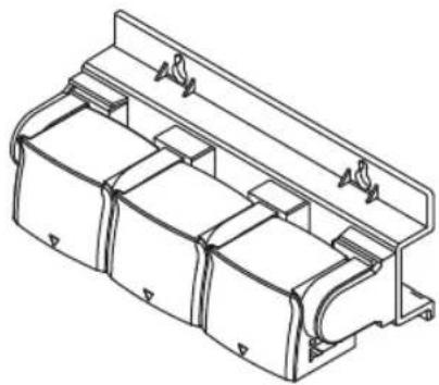
natural_image
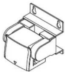
Technical line drawing of a mechanical housing or enclosure component (no text or symbols)Filter Head Connection Assembly
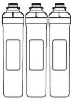
natural_image
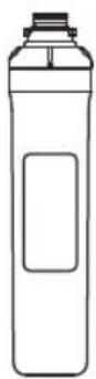
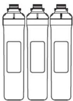
Three identical line-drawn bottles with blank labels, no text or symbols present3 Filters: Sediment Filter Pre-Carbon Filter Carbon Block Filter
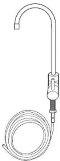
natural_image
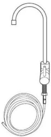
Line drawing of a laboratory gas collection device with tubing and cap (no text or symbols)LED Indicator Faucet Assembly with attached tubing (blue)
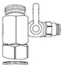
natural_image
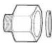
Technical line drawing of a mechanical valve assembly (no text or symbols)Water Supply T-Valve with Rubber Washer (1/2" connection)
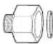

T-Valve Adapters with Rubber Washer 1/2" to 3/8"
natural_image
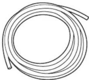
Simple line drawing of a coiled cable or hose (no text or symbols)Water Supply Tubing

Mounting Screws
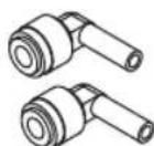
Quick Connect
90° Elbows
UC100 PRODUCT COMPONENTS
natural_image
Technical line drawing of a mechanical bracket or housing component (no text or symbols)Filter Head Connection Assembly
1 Filter: Carbon Block Filter
natural_image
Line drawing of a medical or laboratory device with a coiled tube and tubing (no text or symbols)LED Indicator Faucet Assembly with attached tubing (blue)

natural_image
Technical line drawing of a mechanical valve assembly (no text or symbols)Water Supply T-Valve with Rubber Washer (1/2" connection)

T-Valve Adapters with Rubber Washer 1/2" to 3/8"

natural_image
Simple line drawing of a coiled cable or tube (no text or symbols)Water Supply Tubing

Mounting Screws

Quick Connect 90° Elbows
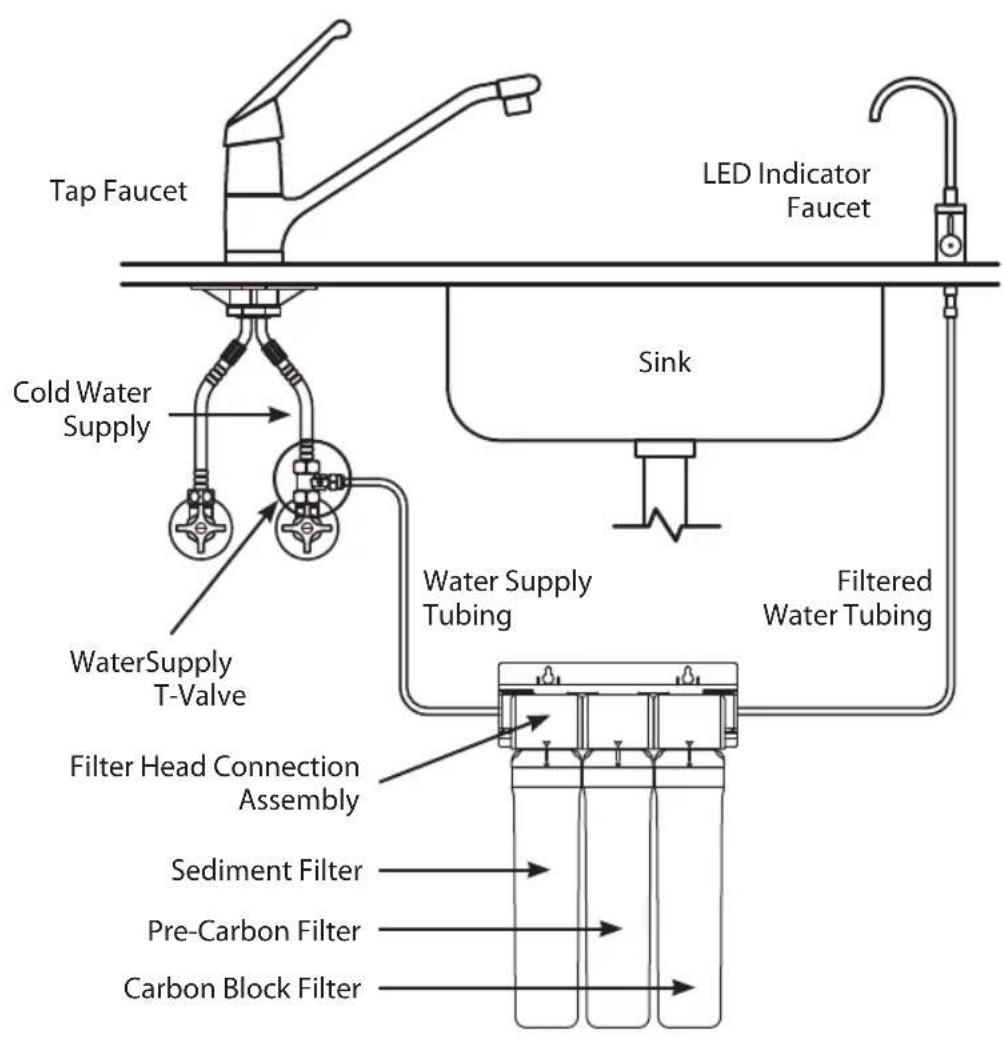
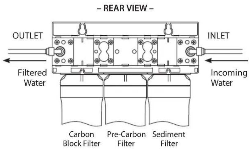
UC300 WATER FLOW DIAGRAM
flowchart
graph TD
    A["Tap Faucet"] --> B["Cold Water Supply"]
    B --> C["WaterSupply T-Valve"]
    C --> D["Filter Head Connection Assembly"]
    D --> E["Sediment Filter"]
    D --> F["Pre-Carbon Filter"]
    D --> G["Carbon Block Filter"]
    H["LED Indicator Faucet"] --> I["Sink"]
    I --> J["Water Supply Tubing"]
    J --> K["Filtered Water Tubing"]
    K --> L["End"]
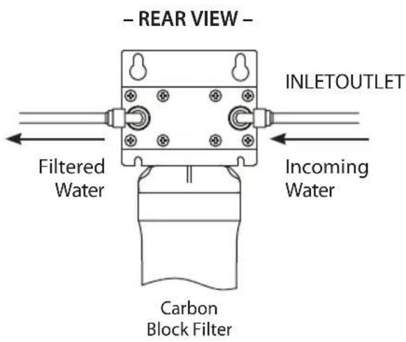
UC100 WATER FLOW DIAGRAM
flowchart
graph TD
    A["Tap Faucet"] --> B["Cold Water Supply"]
    B --> C["WaterSupply T-Valve"]
    C --> D["Filter Head Connection Assembly"]
    D --> E["Carbon Block Filter"]
    F["LED Indicator Faucet"] --> G["Sink"]
    G --> H["Water Supply Tubing"]
    H --> I["Filtered Water Tubing"]
    I --> J["End"]
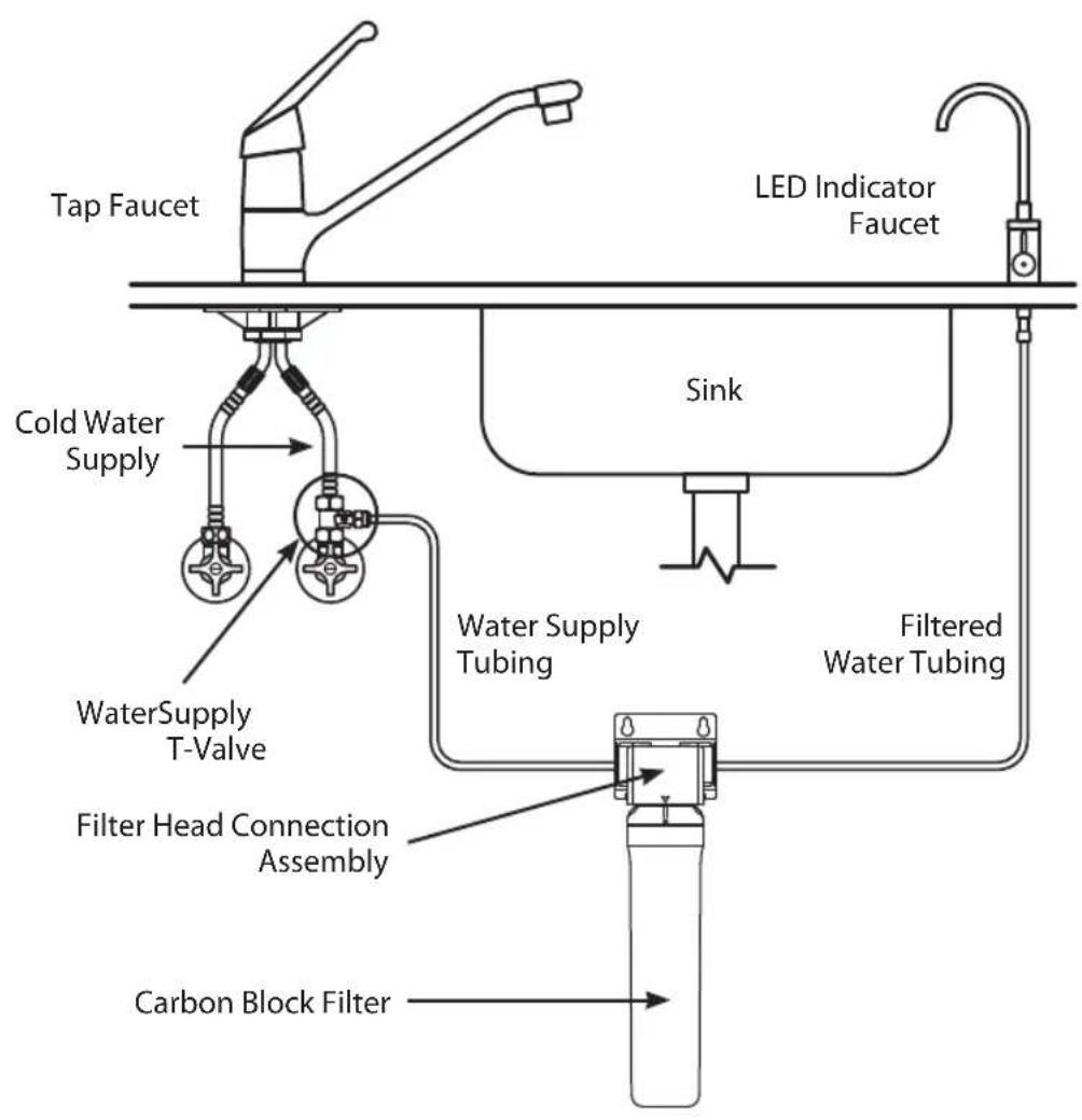
PRODUCT INSTALLATION

Do not install the Filter Head Connection Assembly further than 12 feet away from either the water supply valve, or the Indicator Faucet.
Avoid unnecessary slack in the supply hoses when connecting to the water supply, Filter Head Connection Assembly, or Indicator Faucet.
Do not install in direct sunlight, or a place where it will be directly exposed to freezing temperatures.
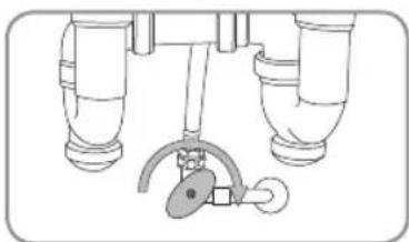
STEP 1: T-VALVE INSTALLATION

Be sure to install the T-Valve on the cold water supply line. Running hot water through the Coral Water Filtration System will damage the filters.
- Close the cold water supply valve. Place a bucket, or similar item, underneath the valve to catch any water that may spill out during installation.
- Unscrew the hose that connects the cold water supply valve to the existing tap water faucet.
- Ensure the rubber washer is inside the T-Valve, and then screw the T-Valve Adapter onto the cold water supply valve.
NOTE: If the water supply valve is smaller than the 1/2" connection on the T-Valve, use the included 3/8" Valve Adapters with Rubber Washers to connect the T-Valve and the water supply hose.
- Screw the cold water supply hose to the top of the T-Valve. Be sure to keep the water supply valve closed.
natural_image
Diagram of a mechanical or plumbing assembly with two vertical pipes and a curved pipe attachment (no text or symbols)
natural_image
Technical line drawing of a mechanical assembly with three cylindrical components and a valve (no text or symbols)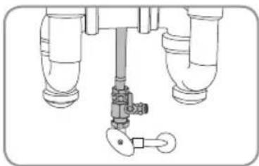
natural_image
Technical diagram of a mechanical valve assembly with three pipes and a key (no text or labels)PRODUCT INSTALLATION (cont.)
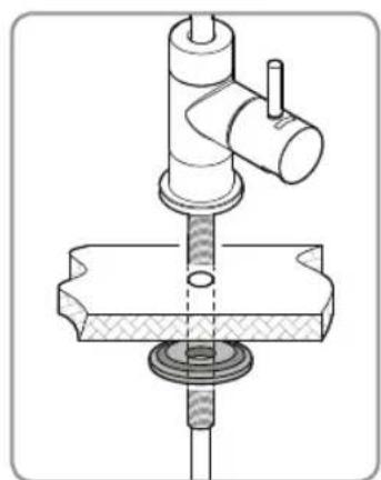
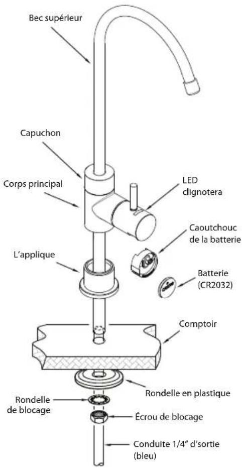
STEP 2: FAUCET INSTALLATION
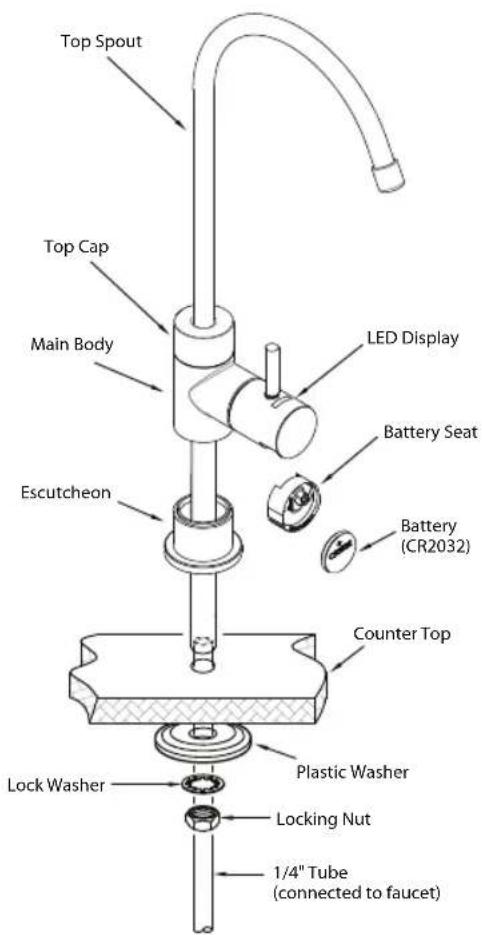
Before Installation
You will need an existing faucet hole at least 7/16 inches in diameter in the sink or countertop to install the supplied filtered water faucet. You may also replace an existing kitchen sprayer, soap dispenser, or plug already on the countertop or sink.

If drilling a new hole is required for the faucet installation, please consult a professional. Brondell will not be liable for any damages including those to the sink or countertop due to installation of the faucet or drilling a hole.
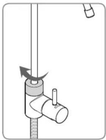
- Unpack the faucet and insert the Top Spout into the Main Body by pushing down until inserted then screw the Top Cap clockwise until secured in place.
- Cut zip tie on the blue water connection tubing and unroll to straighten tubing. Be careful not to cut the tube when removing the zip tie.
natural_image
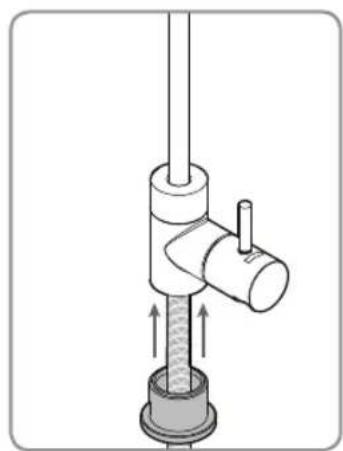
Diagram of a mechanical device with a rotating lever and adjustment knob (no text or symbols)- Attach the Escutcheon to the Main Body by inserting the blue tubing through it and pushing it all the way up until connected to the Main Body.
natural_image
Mechanical assembly diagram showing a valve with internal components and directional arrows (no text or labels)- Install the faucet on top of the countertop or sink and feed the blue tubing through the hole to the cabinet below. Then slide the large Plastic Washer as shown up through the blue tubing until snug against the bottom of the countertop or sink hole. Be sure that the flat part of the Washer is facing down and the raised area is facing up as shown here.
natural_image
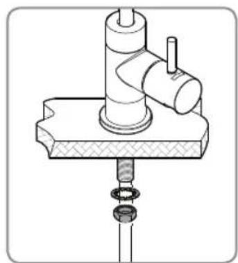
Technical line drawing of a mechanical assembly with no visible text or symbols- Install the Lock Washer and the Locking Nut the same way and tighten until the plastic washer is holding the faucet assembly firmly in place. The faucet is now installed.
natural_image
Technical illustration of a mechanical assembly with a cylindrical component and threaded base (no text or symbols)- Pull the plastic tab out from the battery compartment to activate the faucet indicator. The LED light will blink red once, blue once, and then will be ready to go.
PRODUCT INSTALLATION (cont.)
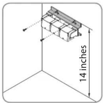
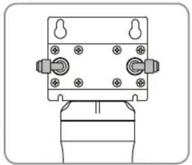
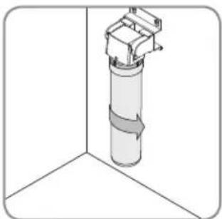
STEP 3: FILTER HEAD CONNECTION ASSEMBLY INSTALLATION
- Attach the two Quick Connect 90° Elbows to back side of the Connection Assembly Inlet and Outlet as shown
natural_image
Technical line drawing of a mechanical assembly with mounting holes and housing (no text or symbols)UC300 UC100
natural_image
Technical line drawing of a mechanical component with mounting holes and a base (no text or symbols)
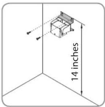
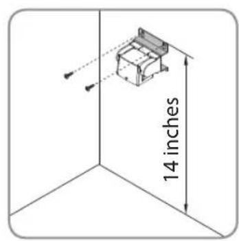
Be sure to install the Filter Head Connection Assembly so that the top of the assembly is at least 14 inches from the floor of the sink cabinet. Otherwise the filters will not install or seat correctly.
- Using a pencil, mark where the Filter Head Connection Assembly will be mounted to the sidewall of the cabinet (at least 14" from the cabinet floor). Use a level to make sure that the Assembly will be mounted straight.
NOTE: Before you mount the Connection Assembly, it may be a good idea to practice inserting and removing the filters.
- Insert the two mounting screws through the holes in the Assembly frame and screw into the cabinet sidewall.
UC300 UC100
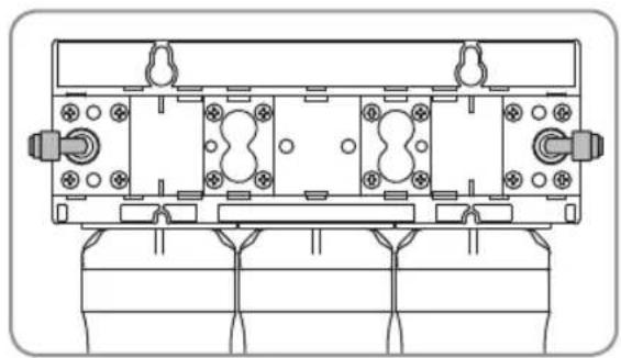
STEP 4: INSTALLING THE FILTERS
NOTE: For purchasers of the Coral UC300, it is very important to install the filters in the correct order. Simply match the same label colors to the filter head labels. From left-to-right, the proper order is
1) Sediment filter
2) Pre-Carbon filter
3) Carbon Block filter
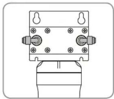
- To insert the filters, first line up the arrow on the filter head with the arrow on the filter
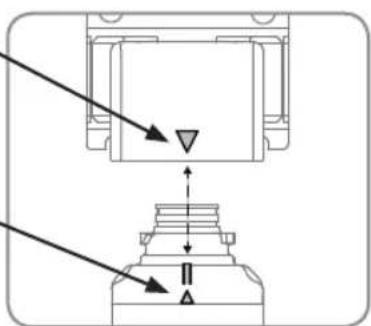
- With the top and bottom arrows still lined up, insert the top of the filter into the housing and turn 90 degrees to the right, until the filter will not turn any more.
The Filter Head arrow should now be lined up with the "Circle" icon and notch on the top of the filter.
natural_image
Diagram of a cylindrical structure with directional arrows indicating flow or movement, no text or symbols presentUC300 UC100

natural_image
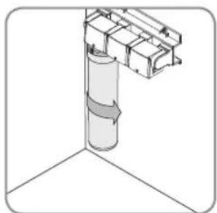
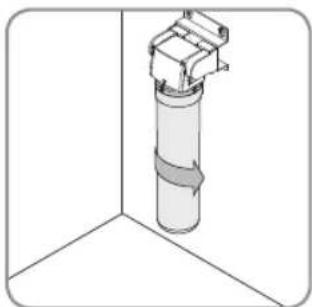
3D diagram of a cylindrical mechanical component mounted on a vertical surface, with no visible text or symbols.3a. For UC300 – Repeat the process for the Pre-Carbon filter and Carbon Block filter.
3a. For UC100 - This process is complete.
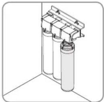
natural_image
3D diagram of a cylindrical container with two transparent containers mounted on top, enclosed in a corner frame (no text or symbols)PRODUCT INSTALLATION (cont.)
STEP 5: CONNECTING THE TUBING
Using "Quick Connectors"
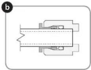
Tube connections on the T-Valve, Filter Head Connection Assembly, and Indicator Faucet are all of the "Quick Connect" variety. The steps below illustrate how to connect and disconnect the Tubes from these connectors.
a. Push the Tube into the Collette. The Collette is a collar that provides a secure fit for the Tube and prevents water leaks.
b. Push the Tube in until it stops. The Tube will be secure, and resistant to tugs or pulls. The Collette will be rigid and raised slightly from the connector housing.
c. To disconnect the Tube, push down and hold the Collette first, and then pull the Tube out gently.
natural_image
Pure mechanical assembly diagram without any text, numbers, or symbols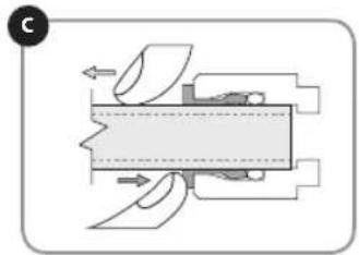
natural_image
Pure mechanical assembly diagram without any text, numbers, or symbols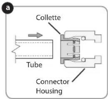
- Water Supply Connection
Use the supplied white color Water Supply Tubing to connect the T-valve to the Filter Head Connector Assembly by pushing one end of the tubing firmly into the Quick Connector Collette on the open side of the T-Valve. Be sure to push in all the way and ensure the Tube is not bent or kinked.
Then connect the other open end of the Tubing to the Filter Head Connector Assembly "Inlet" by inserting the tube into the Collette on the Quick Connect 90 (degree symbol) Elbow on the side labeled "Inlet" (nearest to the Sediment filter)
- Faucet Connection
Now, connect the open end of the Blue Tubing coming from the Faucet to the Filter Head Connector Assembly "Outlet" by inserting the Tube into the Collette on the Quick Connect 90° Elbow on the side labeled "Outlet" (nearest to the Carbon Block Filter). Be sure to push in firmly all the way and ensure the Tube is not bent or kinked.
PREPARING FOR USE
TURN ON WATER & CHECK FOR LEAKS

Before turning the cold water valve back on, review the installation instructions to ensure that the T-Valve and water hoses are connected correctly and securely.
- Turn on water supply
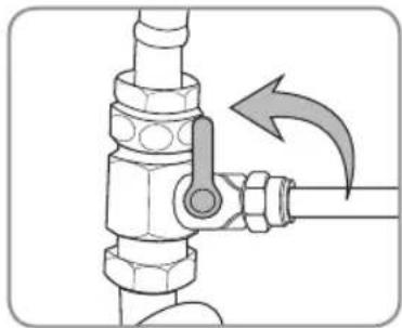
a. Open the T-Valve by turning the valve arm 90° as shown.
b. Turn the cold water supply valve at the wall counterclockwise to turn on. The cold water supply will then begin to supply water to the Coral UC300 or UC100.
natural_image
Mechanical diagram showing a valve assembly with a rotating arrow indicating motion (no text or symbols)- Checking for leaks
a. Once the water supply has been turned on, check for any signs of leaking throughout the system.
b. If no leaks are found, wait 5 minutes and check one more time. If still no leaking, then continue to next step to flush the system.

Failure to properly install this product or to properly check for leaks may cause damage to the property. In these instances, Brondell, Inc. will not be held responsible for any damages.
FLUSHING THE SYSTEM
- Turn the Indicator Faucet on and let the water flow from the faucet for 5 minutes continuously to flush the system and activate the filter(s).
- Check one last time for any leaks during this process.
- Your Coral system is now ready to use!
FILTERS & FILTER CHANGE INDICATOR
FILTERS
The filters are critical to the performance of the Coral UC Water Filtration system, and it is important to replace all of the filters on a regular basis. If any of the filters are overused beyond the recommended service life, the performance of the water filtration device can deteriorate. Do not miss the filter replacement cycle or use non-compatible filters as this can affect system performance or damage the unit.
Contact Brondell at 888-542-3355, or visit us at www.brondell.com to order replacement filters.
FILTER CHANGE INDICATOR
The LED filter change indicator in the faucet works by tracking both time and water flow from the Coral UC system.
UC300 – When 12 months have elapsed or 600 gallons of water has been filtered through the system (whichever comes first), the LED will flash red when dispensing water instead of flashing blue.
UC100 – When 6 months have elapsed or 300 gallons of water has been filtered through the system (whichever comes first), the LED will flash red when dispensing water instead of flashing blue.
When the faucet LED indicator begins to flash red, it's now time to change the filters and reset the faucet indicator by replacing the battery.
A new battery is always included with the UF-35, or UF-15 filter replacement set.
FILTER REPLACEMENT CYCLE
| Part Number Filter | Name Usable period** | |
| UC300 | ||
| UF-35 | Sediment Filter 12 months | |
| Pre-Carbon Plus Filter 12 months | ||
| Carbon Block Filter 12 months | ||
| UC100 | ||
| UF-15 Carbon Block Filter 6 months | ||
* The filter replacement cycle may be reduced for areas with poor water quality or greater use.
** The period for the filter exchange is based on an average production of 1.64 gallons of drinking water per day.
MAINTENANCE
REPLACING THE FILTERS
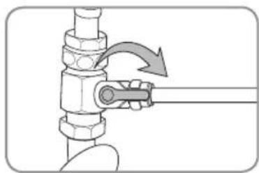
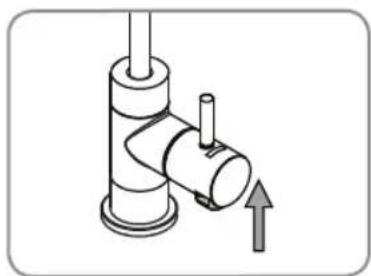
- Close the T-Valve under the sink to shut off the flow of water to the Coral.
natural_image
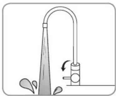
Diagram of a pipe valve assembly with a directional arrow indicating motion (no text or symbols present)- Once the T-valve is shut off, turn the Indicator Faucet on all the way and keep it on until all the residual water in the tubes has been expelled.
natural_image
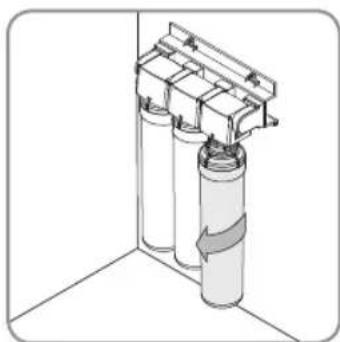
Diagram of a faucet with water spray and valve mechanism (no text or symbols)- Turn the filter(s) to be replaced 90^ to the left, until the filter comes out of the Filter Head Connection Assembly. For the Coral UC300, remove the remaining two filters. For the Coral UC100, the process is complete.
natural_image
Diagram of a cylindrical tank with attached housing and internal components, no text or symbols present-
Install the new filter(s). Review the procedure outlined on Page 13.
-
Open the T-Valve to restore the flow of water and turn the Indicator Faucet on for 5 minutes continuously to flush and activate the new filter(s).
Be sure to reset the Indicator Faucet by following the next steps.
MAINTENANCE (cont.)
REPLACING THE FILTERS (cont.)
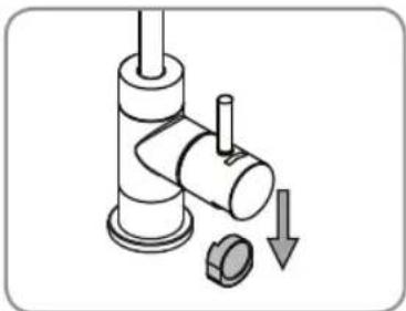
- Replace the battery in the faucet LED indicator to reset the filter change reminder. The battery type is CR2032 and Brondell provides one with every set of UF-35 and UF-15 filters.
a. Under the faucet handle, locate the black rubber battery compartment. Grasp it from the sides and pull down as shown.
b. Remove the old battery from the compartment by lifting the silver metal tab and sliding the battery out of the rubber casing. Wait 30 seconds for the residual energy to drain to reset the indicator.
c. Replace with a new CR2032 battery by sliding the battery under the silver tab, making sure that the words on the battery are facing out. A fresh CR2032 battery comes with every UF-35 and UF-15 Replacement Filter pack.
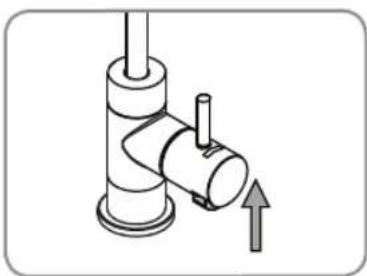
d. Push the black rubber battery compartment back up into the faucet handle.
e. The indicator will blink red once, blue once, and then the indicator will function as normal.
natural_image
Diagram of a pipe fitting with a valve and a bolt, showing a downward arrow indicating a process (no text or symbols present)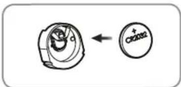
natural_image
Mechanical diagram showing a valve assembly with a directional arrow (no text or symbols)TROUBLESHOOTING
| Problem Possible | Cause Solution | |
| There is no water flow. | Incoming cold water supply valve is turned off. | Turn on incoming cold water supply valve. |
| There is not enough water flow. | The tubing is bent or twisted. | Straighten out the hose. If water flow is still impacted, replace the hose. |
| The water supply valve is not turned on all the way. | Ensure the water supply valve is open completely. | |
| The temperature of the tap water decreased sharply. | If the water temperature decreases due to inclement weather, water will flow more slowly through the system than normal. | |
| The life of one or more of the filters has run out. | Replace the filters, per the instructions on Page 17. | |
| The water tastes or smells bad. | The life of the filters has expired. | Replace the filters, per the instructions on Page 17. |
| There is a leak surrounding one of the hose connections. | The tubing is not inserted into the quick connector completely. | Ensure the hose is inserted completely. |
| The end of the tube is damaged. | Cut the tubing off at the damaged area and connect the tube again, or replace the tubing entirely. | |
| Water is leaking from the head Connection Assembly. | An O-ring on one of the filters is damaged. | Determine which filter or filters are affected and contact the Brondell service center. |
PRODUCT SPECIFICATIONS
| Product name Coral Three-Stage Undercounter Water Filtration System | |
| Model | UC300 |
| Filters | Sediment, Pre-Carbon, Carbon Block (UF-35) |
| Product Dimensions | 9" (W) x 13.5" (H) x 3.75" (D) |
| Working temperature | 39°F – 100°F (4°C – 38°C) |
| Working pressure | 35 psi – 100 psi (241 kPa – 689 kPa) |
| Net weight | 3.8 lbs. (1.72 kg) |
| Product name Coral Single-Stage Undercounter Water Filtration System | |
| Model | UC100 |
| Filter | Carbon Block (UF-15) |
| Product Dimensions | 3.5" (W) x 13.5" (H) x 3.75" (D) |
| Working temperature | 39°F – 100°F (4°C – 38°C) |
| Working pressure | 35 psi – 100 psi (241 kPa – 689 kPa) |
| Net weight | 1.8 lbs. (0.82 kg) |
Service flow rate and production rate can differ with varying water temperature and water pressure.
Without any prior notice, all or parts of the product are subject to change for the purpose of improving the performance of the product.
CORAL UC300/UC100 Filtration System Performance Data Sheet


Models: Coral UC300 & UC100
This system has been tested and certified by the Water Quality Association according NSF/ANSI 42 and 53 for the reduction of the substances listed below. The concentration of the indicated substances in water entering the system was reduced to a concentration less than or equal to the permissible limit for water leaving the system, as specified in NSF/ANSI 42 and 53. The system has also been tested and certified by WQA according to NSF/ANSI 372 and CSA B483.1.
| Substance | Average Percent Reduction | Influent Challenge Concentration (mg/L unless specified) | Maximum Permissible Product Water Concentration or Minimum Allowable % Reduction (mg/L unless specified) | |
| NSF/ANSI 42 Aesthetic Effects | Chlorine, Taste, & Odor 98.0% | 2.00 ± 10% ≥ 50% Reduction | ||
| Chloramine 98.6% 3.00 | ± 10% 0.5 | |||
| Particulate Class 1 particles 0.5 to < 1μm | 99.8% | minimum 10,000 particles/mL | ≥ 85% Reduction | |
| NSF/ANSI 53 Health Effects | Cyst 99.99% | minimum 50,000 particles/L | ≥ 99.95% Reduction | |
| Mercury Reduction pH 8.5 96.9% | 0.006 ± 10% 0.002 | |||
| Mercury Reduction pH 6.5 96.9% | 0.006 ± 10% 0.002 | |||
| Lead Reduction pH 8.5 99.2% | 0.15 ± 10% 0.010 | |||
| Lead Reduction pH 6.5 99.7% | 0.15 ± 10% 0.010 | |||
| MTBE Reduction 96.9% | 0.015 ± 10% 0.005 | |||
| Turbidity 96.6% 11 ± 1 NTU 0.5 NTU | ||||
| VOC Surrogate Test 99.8% | 3.00 ± 10% ≥ 95% Reduction | |||
| Asbestos Reduction | 99.96% | 100-1000 MFL | ≥ 99% Reduction | |
While testing was performed under laboratory conditions, actual performance may vary.
General Operating Information:
| UC300 Rated Capacity | 600 gallons (2271 L) |
| UC100 Rated Capacity | 300 gallons (1135 L) |
| Min-Max operating pressure: | 35 psi – 100 psi (241 kPa – 689 kPa) |
| Min-Max feed water temperature: | 39^ F - 100^ F (4^ C - 38^ C) |
| Rated Service Flow | 0.50 gpm (1.89 lpm) |
- Do not use with water that is microbiologically unsafe or of unknown quality without adequate disinfection before or after the system.
- Refer to the owners manual for specific installation instructions, manufacturer's limited warranty, user responsibility, and parts and service availability.
• For parts and service availability, please contact Brondell. - The estimated replacement time of filter, which is a consumable part, is not an indication of quality guarantee period, but it means the ideal time of filter replacement. Accordingly, the estimated time of filter replacement may be shortened in case it is used in an area of poor water quality.
• System and installation shall comply with all state and local regulations.
• Systems certified for cyst reduction may be used on disinfected waters that may contain filterable cysts.
CORAL UC300/UC100 Filtration System Performance Data Sheet
| Part Number Filter | Name Usable period | |
| UF-35 for UC300 | Sediment Filter 12 months | |
| Pre-Carbon Filter 12 months | ||
| Carbon Block Filter 12 months | ||
| UF-15 for UC300 | Carbon Block Filter 6 months |
* The filter replacement cycle may be reduced for areas with poor water quality or greater use.
* The period for the filter exchange is based on an average production of 2.6 gallons of drinking water per day.
* Chloroform was used as the surrogate chemical for VOC reduction claims
Brondell, Inc
PO Box 470085
San Francisco, CA 94147
www.brondell.com 1-888-542-3355
1 These harmonized values were agreed upon by representatives of USEPA and Health Canada for the purpose of evaluating products to the requirements of this Standard.
2 Influent challenge levels are average influent concentrations determined in surrogate qualification testing.
3 Maximum product water level was not observed but was set at the detection limit of the analysis.
4 Maximum product water level is set at a value determined in surrogate qualification testing.
5 Chemical reduction percent and maximum product water level calculated at chloroform 95% breakthrough
point as determined in surrogate qualification testing.
6 The surrogate test results for heptachlor epoxide demonstrated a 98% reduction. These data were used to
calculate an upper occurrence concentration which would produce a maximum product water level at the MCL.
WARRANTY
Brondell products are backed by some of the most comprehensive warranties in the industry. Brondell warrants that the H2O+ water filtration system shall be free from defects in material and workmanship under normal use and service.
Brondell H2O+ Coral Water Filtration System, Models UC100 and UC300 – One Year Warranty 100% Coverage of all parts and labor for the entire product for the first year from original date of purchase. This does not apply, however, to consumable filters.
Exclusions and Limitations
-
BRONDELL warrants its products to be free from manufacturing defects under normal use and service. This warranty is extended only to the ORIGINAL PURCHASER.
-
BRONDELL's obligations under this warranty are limited to repairs or replacement, at BRONDELL's option, of products or parts found to be defective, provided that such products were properly installed and used in accordance with instructions. BRONDELL reserves the right to make such inspections as may be necessary in order to determine the cause of the defect. BRONDELL will not charge for labor or parts in connection with warranty repairs for the first full year from date of purchase on all products except those that may be subject to commercial use limitations.
-
BRONDELL is not responsible for the cost of removal, return (shipping) and/or reinstallation of products. This warranty does NOT apply to:
Damage or loss which occurs during shipment.
Damage or loss sustained through any natural or man-made causes beyond the control of BRONDELL, including but not limited to fire, earthquake, floods, etc.
Damage or loss resulting from sediments or foreign matter contained in a water system.
Damage or loss resulting from negligent or improper installation including installation of a unit in a harsh or hazardous environment.
Damage or loss resulting from removal, improper repair, modification of the product, or improper maintenance including damage caused by chlorine or chlorine related products
Damage or loss resulting from acts which are not the fault of Brondell or which the Product is not specified to tolerate.
- This warranty gives you specific legal rights. You may have other rights which vary from state to state.
THIS WRITTEN WARRANTY IS THE ONLY WARRANTY MADE BY BRONDELL. REPAIR OR REPLACEMENT AS PROVIDED UNDER THIS WARRANTY SHALL BE THE EXCLUSIVE REMEDY AVAILABLE TO THE PURCHASER. BRONDELL SHALL NOT BE RESPONSIBLE FOR LOSS OF USE OF THE PRODUCT OR FOR OTHER INCIDENTAL, SPECIAL, FOR CONSEQUENTIAL DAMAGES OR EXPENSES INCURRED BY THE PURCHASER OR FOR LABOR OR OTHER COSTS DUE TO INSTALLATION OR REMOVAL OR COSTS OF REPAIRS BY OTHERS, OR FOR ANY OTHER EXPENSE NOT SPECIFICALLY STATED ABOVE. EXCEPT TO THE EXTENT PROHIBITED BY APPLICABLE LAW, ANY IMPLIED WARRANTIES, INCLUDING THAT OF MERCHANTABILITY, ARE EXPRESSLY LIMITED TO THE DURATION OF THIS WARRANTY. SOME STATES DO NOT ALLOW LIMITATIONS, SO THE ABOVE LIMITATION AND EXCLUSION MAY NOT APPLY TO YOU.
How to Obtain Service
To obtain repair service under this warranty, you must contact an authorized BRONDELL Service Center to obtain an RMA (Return Merchandise Authorization) number. Proof of purchase in the form of a copy of the original receipt must accompany the returned unit for the warranty to be valid. Take or ship the unit prepaid to the closest Brondell authorized service center along with the RMA number and proof of purchase.
To obtain the RMA number and locate the BRONDELL Service Center location nearest you, please call 1-888-542-3355.
brondell®
a healthy home experience
CONTACT:
Brondell, Inc.
PO Box 470085
San Francisco, CA 94147-0085
Phone: 1-888-542-3355
Email: support@brondell.com
Web: www.brondell.com
For questions, contact Brondell Customer Service: 1-888-542-3355
MANUFACTURED BY:
Brondell, Inc.
PO Box 470085
San Francisco, CA 94147-0085
ESTIMATED COST OF REPLACEMENT FILTERS:
UF-15 1-filter for UC100 - \$59.95
UF-35 3-filter set for UC300 - \$119.95
California Department of Public Health Certification: Certification Number: on file*
Iowa Department of Public Health Registration: WTD Number: on file*
Wisconsin Department of Commerce: Product File Number: on file*
Brondell's H2O+ Coral UC300 Three-Stage & UC100 Single-Stage Under Counter Water Filtration System has been tested and certified by WQA according to NSF/ANSI 42 (for the reduction of Aesthetic Chlorine – taste & odor, Chloramine, and Particulate Class 1), NSF/ANSI 53 (for Cyst, Turbidity, Asbestos, Mercury, Lead, MTBE, and VOC reduction), and NSF/ANSI 372 (for low lead compliance) as verified and substantiated by test data.

C USA
The following is required for Iowa purchases only. A copy of this document must be retained by seller for 2 years.
Buyer: ____
Date: ____
Buyer's Address:
Seller:
Date: ____
Seller's Address:
CORAL
MANUAL DEL USUARIO
natural_image
Product photos of three Brondell water purifiers with metal fittings and control valves (no visible text or labels)ÍNDICE
natural_image
Technical line drawing of a mechanical housing or enclosure component (no text or symbols)Cabeza del filtro 3 Filtros:
natural_image
Three identical plastic bottles with black caps and blue labels, arranged horizontally (no text or symbols)natural_image
Line drawing of a hand pump with a coiled hose and valve (no text or symbols)natural_image
Technical line drawing of a mechanical valve assembly (no text or symbols)natural_image
Simple line drawing of a coiled cable or hose (no text or symbols)natural_image
Technical line drawing of a mechanical bracket or housing component (no text or symbols)Cabeza del filtro 1 Filtro:
natural_image
Line drawing of a medical catheter with tubing and cap (no text or symbols)natural_image
Technical line drawing of a mechanical valve assembly (no text or symbols)natural_image
Simple line drawing of a coiled cable or tube (no text or symbols)natural_image
Diagram of a mechanical or electrical component with two vertical pipes and a curved pipe connection (no text or symbols)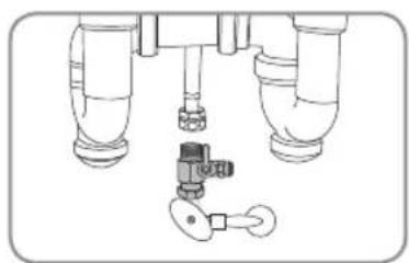
natural_image
Diagram of a mechanical valve assembly with three pipes and a key (no text or labels)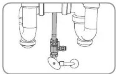
natural_image
Technical line drawing of a mechanical valve assembly with no visible text or symbolsnatural_image
Diagram of a mechanical device with a lever and adjustment arrow (no text or symbols)natural_image
Diagram of a mechanical device with a shaft and valve, showing fluid flow direction (no text or symbols)natural_image
Technical line drawing of a mechanical assembly with no visible text or symbolsnatural_image
Technical line drawing of a mechanical assembly with no visible text or symbolsnatural_image
Technical line drawing of a mechanical assembly with mounting holes and internal components (no text or symbols)UC300 UC100
natural_image
Technical line drawing of a mechanical component with mounting holes and a base (no text or symbols)
UC300 UC100
natural_image
3D diagram of a cylindrical mechanical component with directional arrows indicating flow or movement (no text or symbols)UC300 UC100
natural_image
3D diagram of a cylindrical mechanical component with a bracket, shown in isometric view against a 3D cube (no text or symbols)natural_image
3D diagram of two cylindrical containers mounted on a shelf, no text or symbols presentnatural_image
Pure mechanical assembly diagram without any text, numbers, or symbols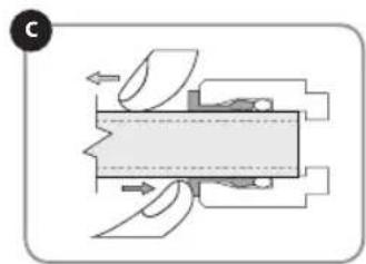
natural_image
Mechanical assembly diagram showing internal components and motion arrows (no text or labels)natural_image
Diagram of a mechanical valve assembly with a hand holding a shaft (no text or symbols)- Revisión de fugas
natural_image
Diagram of a pipe fitting with a valve and directional arrow indicating motion (no text or symbols)natural_image
Illustration of a showerhead spraying water with an arrow indicating flow direction (no text or symbols)natural_image
3D diagram of a cylindrical container with attached housing and a curved pipe, no text or symbols presentnatural_image
Diagram of a pipe fitting with a valve and a circular component, showing a downward arrow (no text or symbols)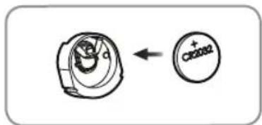
natural_image
Mechanical diagram showing a pipe fitting with a valve and directional arrow (no text or symbols)While testing was performed under laboratory conditions, actual performance may vary.
General Operating Information:
| Capacidad de UC300 | 600 galones (2271 L) |
| Capacidad de UC100 | 300 galones (1135 L) |
| Min-Max Presión Operacional | 35 psi – 100 psi (241 kPa – 689 kPa) |
| Min-Max Temperatura del Agua de Salida | 39°F – 100°F (4°C – 38°C) |
| Flujo de Servicio | 0.50 gpm (1.89 lpm) |
a healthy home experience
CONTACTO:
Brondell, Inc.
PO Box 470085
San Francisco, CA 94147-0085
ESTIMATED COST OF REPLACEMENT FILTERS:
UF-15 Un fi ltro para UC100 - \$59.95
natural_image
Three white watersupers with H2O+ labels being processed by a stainless steel faucet (no visible text or symbols on the devices themselves)
natural_image
Product photo of a Brondell water purifier with a stainless steel faucet (no visible text or symbols on the main subject)
natural_image
Blank document page with a thin line at the top and a rounded corner frame (no text or symbols)TABLE DES MATIÈRES
INSTALLATION DU PRODUIT
63 INSTALLATION DE LA VALVE EN T
64 INSTALLATION DU ROBINET
66 INSTALLATION DE L'ASSEMBLAGE DE CONNEXION DE LA TÊTE DE FILTRE
67 INSTALLATION DES FILTRES
68 CONNEXION DE LA TUYAUTERIE Utilisation des "Quick Connectors"
natural_image
Technical line drawing of a mechanical housing or enclosure component (no text or symbols)natural_image
Three identical line-drawn bottles with blank labels, no text or symbols presentnatural_image
Line drawing of a laboratory gas collection device with tubing and cap (no text or symbols)natural_image
Technical line drawing of a mechanical valve assembly (no text or symbols)natural_image
Simple line drawing of a coiled cable or hose (no text or symbols)natural_image
Technical line drawing of a mechanical bracket or housing component (no text or symbols)natural_image
Line drawing of a laboratory gas collection device with tubing and cap (no text or symbols)natural_image
Technical line drawing of a mechanical valve assembly (no text or symbols)natural_image
Simple line drawing of a coiled cable or tube (no text or symbols)INSTALLATION DU PRODUIT

natural_image
Diagram of a mechanical or plumbing system with two vertical pipes and a curved pipe (no text or symbols)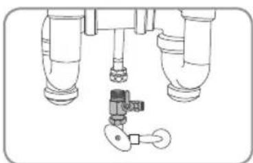
natural_image
Technical line drawing of a mechanical assembly with three cylindrical components and a valve (no text or symbols)
natural_image
Technical line drawing of a mechanical valve assembly with no visible text or symbolsINSTALLATION DU PRODUIT (suite)
ÉTAPE 2 - INSTALLATION DU ROBINET
natural_image
Diagram of a mechanical device with a rotating shaft and lever mechanism (no text or symbols)natural_image
Mechanical assembly diagram showing a valve or pump with directional arrows indicating flow or movement (no text or symbols present)natural_image
Technical line drawing of a mechanical assembly with no visible text or symbolsnatural_image
Technical illustration of a mechanical assembly with a cylindrical component and threaded fastener (no text or symbols)INSTALLATION DU PRODUIT (suite)
ÉTAPE 3 : INSTALLATION DE L'ASSEMBLAGE DE CONNEXION DE LA TÊTE DE FILTRE
natural_image
Technical line drawing of a mechanical assembly with mounting holes and housing (no text or symbols)UC300 UC100

natural_image
Technical line drawing of a mechanical component with mounting holes and a base (no text or symbols)
natural_image
3D diagram of a cylindrical object with directional arrows indicating flow or movement, no text or symbols presentUC300 UC100
natural_image
3D diagram of a cylindrical mechanical component with directional arrows, no text or symbols presentnatural_image
Isometric line drawing of two cylindrical containers mounted on a support structure (no text or symbols)INSTALLATION DU PRODUIT (suite)
ÉTAPE 5 : CONNEXION DE LA TUYAUTERIE
Utilisation des "Quick Connectors"
natural_image
Pure mechanical assembly diagram without any text, numbers, or symbols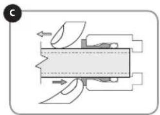
natural_image
Mechanical assembly diagram showing fluid flow through a chamber with no visible text or symbols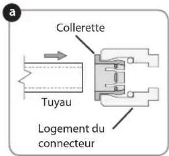
natural_image
Diagram of a mechanical valve assembly with a rotating shaft and valve (no text or symbols)REMPLACEMENT DES FILTRES
natural_image
Diagram of a pipe fitting with a valve and directional arrow indicating motion (no text or symbols)natural_image
Diagram of a showerhead spraying water with a valve, showing fluid flow direction (no text or symbols)natural_image
Diagram of a vertical cylindrical device mounted on a wall, with no visible text or symbolsREMPLACEMENT DES FILTRES (suite)
CARACTÉRISTIQUES DU PRODUIT
a healthy home experience
CONTACTER:
Brondell, Inc.
PO Box 470085
San Francisco, CA 94147-0085
Téléphone: 1-888-542-3355
Email: support@brondell.com
site Web: www.brondell.com