ES1074MG - Basket Atag - Free user manual and instructions
Find the device manual for free ES1074MG Atag in PDF.


User questions about ES1074MG Atag
0 question about this device. Answer the ones you know or ask your own.
Ask a new question about this device
Download the instructions for your Basket in PDF format for free! Find your manual ES1074MG - Atag and take your electronic device back in hand. On this page are published all the documents necessary for the use of your device. ES1074MG by Atag.
USER MANUAL ES1074MG Atag
natural_image
Line drawing of a kitchen air conditioner unit (no text or symbols)GEBRUIKSAANWIJZING
Afzuigkap
NL
WS9074MG
ES1074MG
natural_image
Two black rectangular icons: a plus sign and two gray circular icons with symbols (no text or labels)- Raakde+(plus)toetsaan.
natural_image
Simple circular graphic with a white half-circle and dashed border on black background (no text or symbols)- Raakkortdeverlichtingstoetsaan.
natural_image
Two black-and-white icons: a pie chart and a digital display with Wi-Fi signal, no text or symbols present.natural_image
Three technical diagrams showing structural components of a ceiling frame, with no visible text or symbols.natural_image
Isometric technical diagram of a mechanical assembly with directional arrows indicating movement or force (no text or symbols present)2
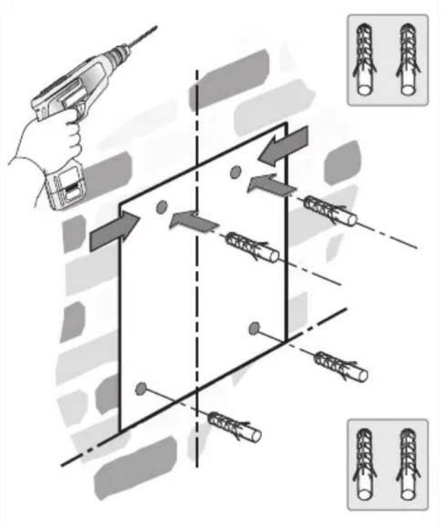
text_image
Diagram illustrating a 3D mechanical assembly with tool, arrows indicating movement, and two inset images showing cylindrical structures.3
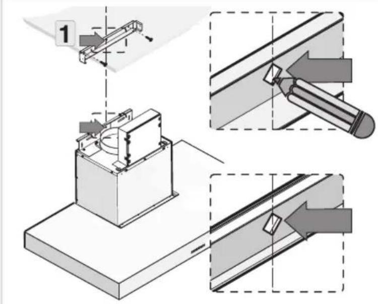
text_image
Technical diagram illustrating a mechanical assembly with labeled components and directional arrows indicating process steps.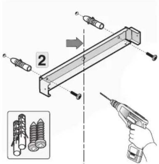
text_image
Technical diagram showing assembly of two screws with a tool, labeled with component '2', and an inset image of screw arrangement.4

text_image
Technical diagram showing mechanical assembly with screws and a pipe connection, annotated with directional arrows and shaded regions.5
text_image
1 D6
text_image
2 G G7
text_image
1
text_image
Technical diagram showing mechanical assembly with labeled component '2' and directional arrow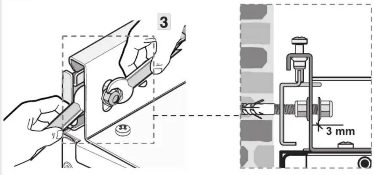
text_image
3 3 mm8
text_image
Technical diagram illustrating a mechanical assembly process with labeled components and directional arrows indicating motion or movement.9
text_image
Technical diagram illustrating four different mechanical assembly steps with numbered instructions and labeled components.Installatie
10
text_image
Technical diagram showing mechanical assembly with two labeled components and a close-up of screw parts, including inset images of bolts.11
natural_image
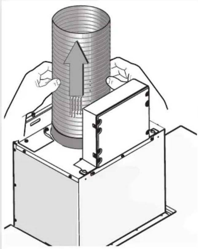
Illustration of hands operating a cylindrical device with an upward arrow, no text or symbols present12
text_image
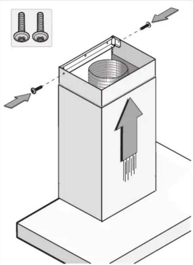
Technical diagram showing a mechanical component with arrows indicating assembly or movement, and inset images of two bolts labeled 'S16' and 'S26'.Eilandafzuigkappen

text_image
1 A A 28 23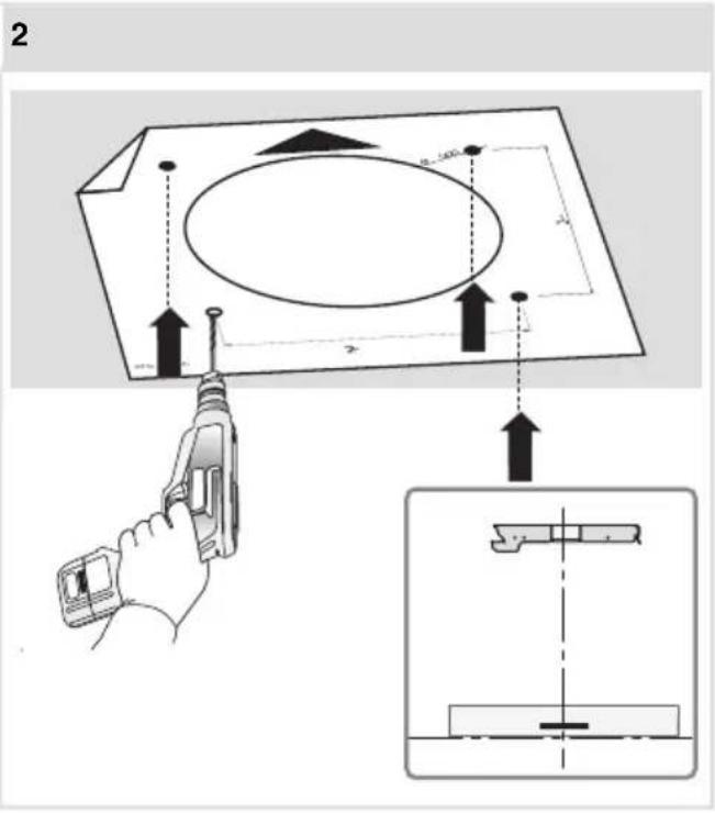
text_image
2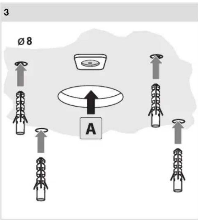
text_image
3 Ø 8 A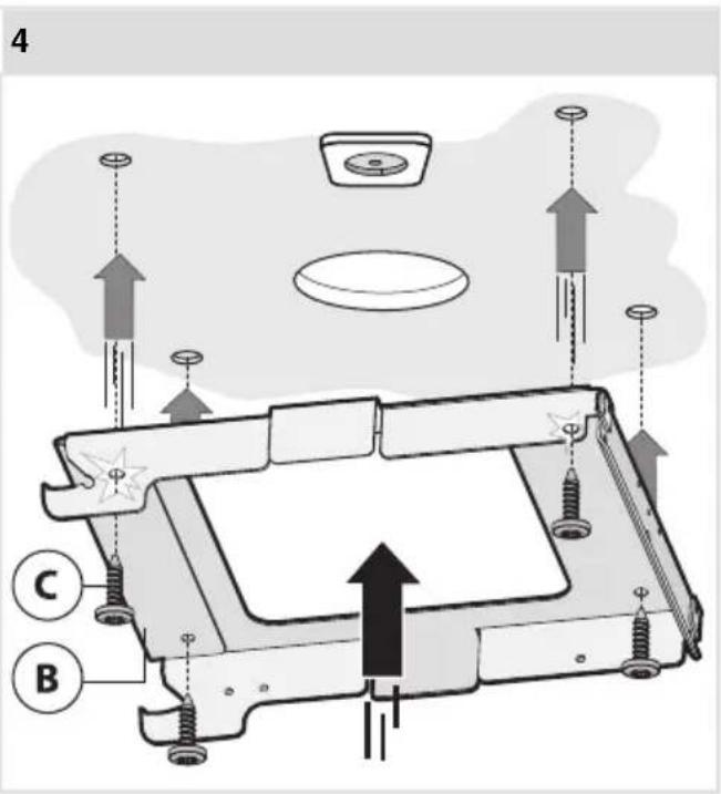
text_image
4 C BInstallatie
5
text_image
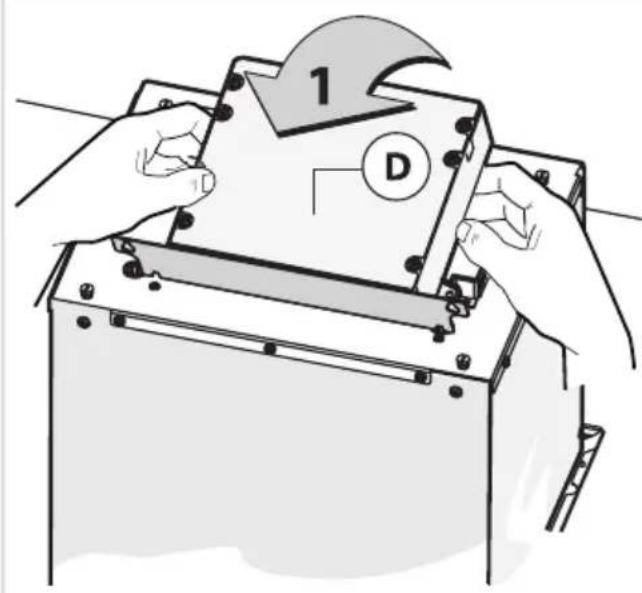
1 D6
text_image
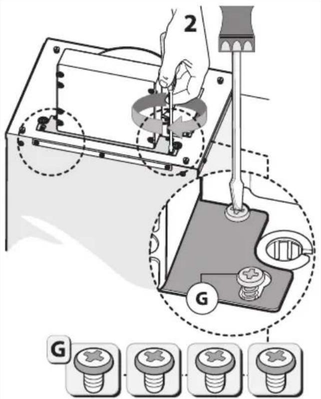
2 G G7
text_image
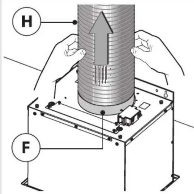
H F8
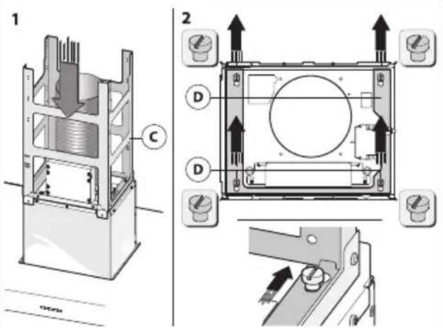
text_image
Technical diagram showing cross-sectional views of a mechanical device with labeled components and directional arrows indicating assembly or movement.9
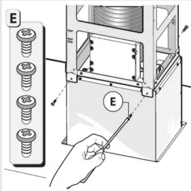
text_image
E E10
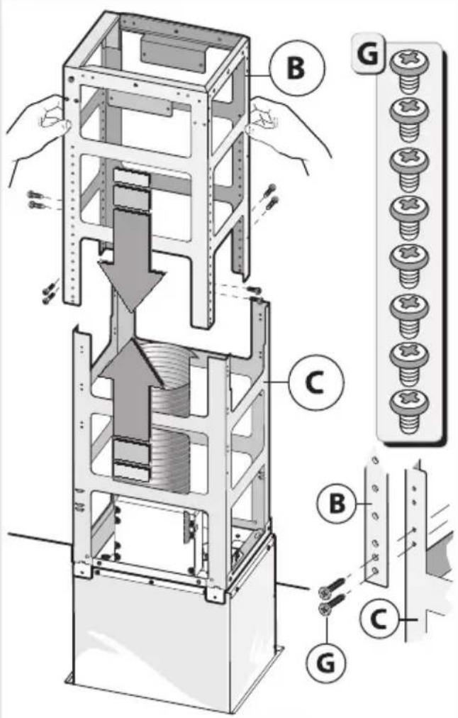
text_image
Technical diagram of a mechanical assembly with labeled parts (B, C, G) and directional arrows indicating movement or force.11
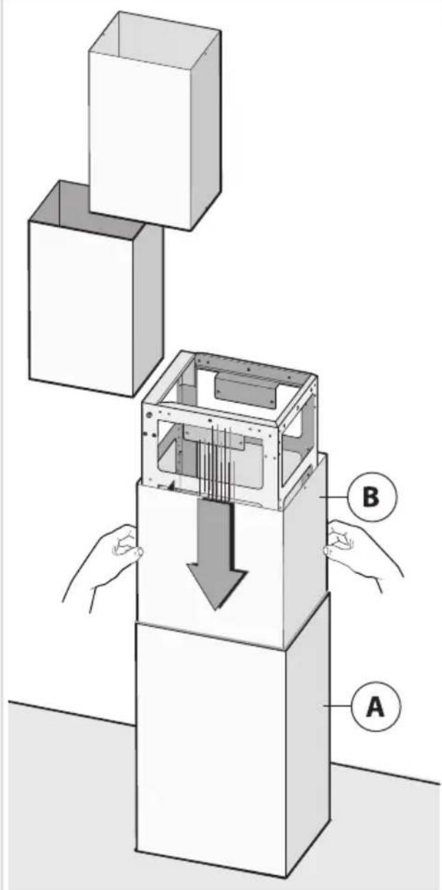
text_image
Diagram illustrating a mechanical assembly with labeled components A and B, showing a downward force on the internal structure.12
text_image
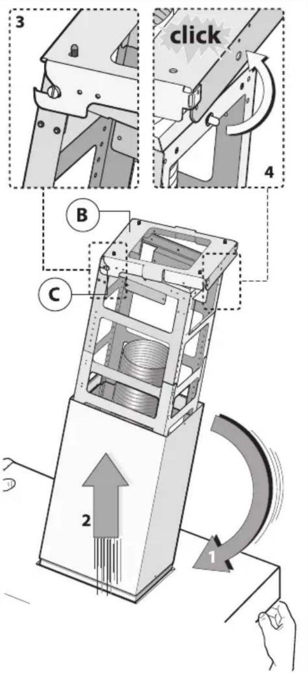
3 click 4 B C 2 113
text_image
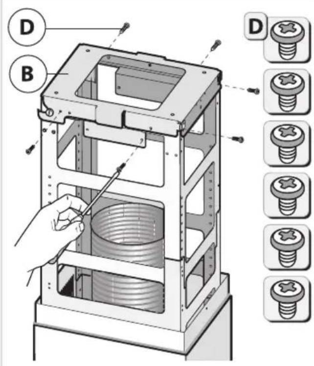
Technical diagram of a mechanical device with labeled parts (D, B) and corresponding screw assembly diagrams.14
text_image
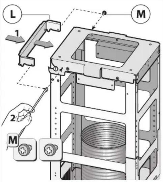
L 1 M 2 M15
text_image
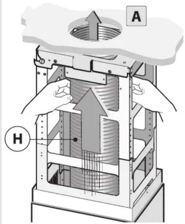
A H16
natural_image
Illustration of a hand using a cable to lift a cylindrical component, with no visible text or symbols.17
text_image
F 2 1 B F Ftext_image
Warning symbol for a trash bin with crossed x and y lines, indicating no waste or discharge.natural_image
Line drawing of a kitchen air conditioner unit with a chimney and ventilation duct (no text or symbols)NOTICED'UTILISATION
Hotteaspirante
FR
WS9074MG
ES1074MG
Tablesdesmatières
natural_image
Two black rectangular icons: a plus sign and two gray circular indicators with icons for smart devices (no text or symbols)natural_image
Simple circular graphic with a white semicircle on a black background, no text or symbols present.natural_image
Simple circular graphic with a white half-circle and radiating lines on a dark background (no text or symbols)Wi-Fi/appConnectLife
natural_image
Three technical diagrams showing structural components of a ceiling frame, with no visible text or symbols.flowchart
graph TD
    A["Top-Down"] --> B["Intermediate"]
    B --> C["Final"]
    C --> D["Recyclable to Disposal"]
flowchart
graph TD
    A["警告"] --> B["操作步骤1"]
    B --> C["操作步骤2"]
    C --> D["操作步骤3"]
    D --> E["操作步骤4"]
    E --> F["操作步骤5"]
    F --> G["操作步骤6"]
    G --> H["操作步骤7"]
    H --> I["操作步骤8"]
    I --> J["操作步骤9"]
    J --> K["操作步骤10"]
    K --> L["操作步骤11"]
    L --> M["操作步骤12"]
    M --> N["操作步骤13"]
    N --> O["操作步骤14"]
    O --> P["操作步骤15"]
    P --> Q["操作步骤16"]
    Q --> R["操作步骤17"]
    R --> S["操作步骤18"]
    S --> T["操作步骤19"]
    T --> U["操作步骤20"]
    U --> V["操作步骤21"]
    V --> W["操作步骤22"]
    W --> X["操作步骤23"]
    X --> Y["操作步骤24"]
    Y --> Z["操作步骤25"]
Éclairage
ATTENTION!
text_image
Technical diagram showing mechanical assembly with screws and a pipe connection, annotated with directional arrows and shaded regions.5
text_image
1 D6
text_image
2 G G7
text_image
1
text_image
Technical diagram showing mechanical assembly with labeled component '2' and directional arrow
text_image
3 3 mm8
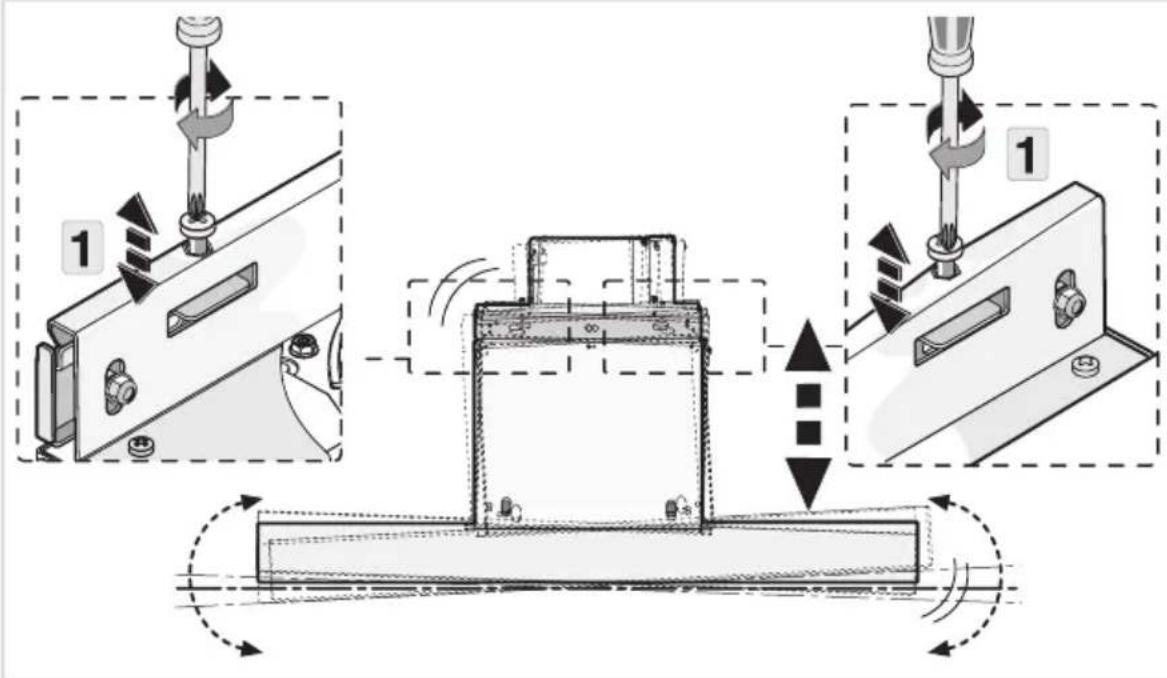
text_image
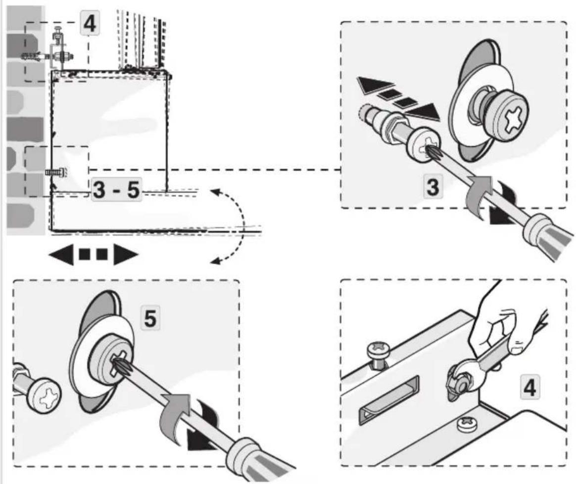
Technical diagram illustrating mechanical assembly steps with labeled components and motion indicators9
text_image
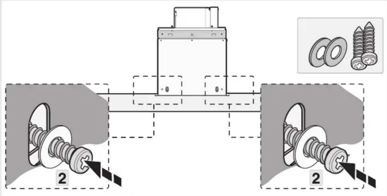
Technical diagram illustrating four different mechanical assembly steps with numbered instructions and labeled components.Installation
10
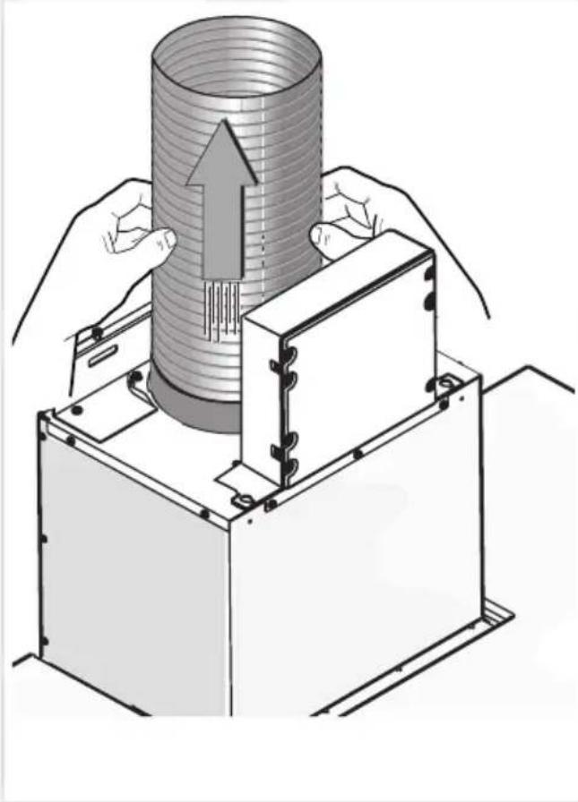
text_image
Technical diagram showing mechanical assembly with two labeled components and a close-up of screw parts, including inset images of washers.11
natural_image
Illustration of hands operating a cylindrical device with an upward arrow, no text or symbols present12

text_image
Technical diagram showing a mechanical component with arrows indicating assembly or movement, and an inset image of two bolts labeled 'SRB' with arrows pointing to the components.Hottesd'îlot
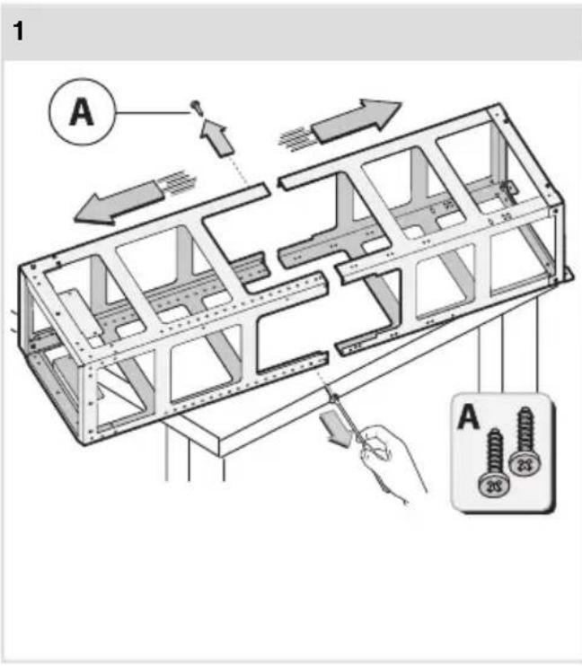
text_image
1 A A 28 23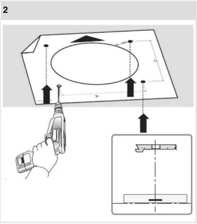
text_image
2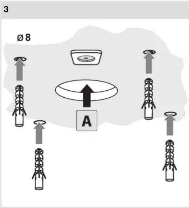
text_image
3 Ø 8 A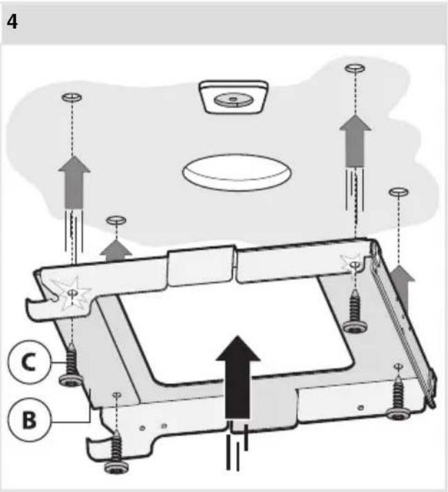
text_image
4 C BInstallation
5
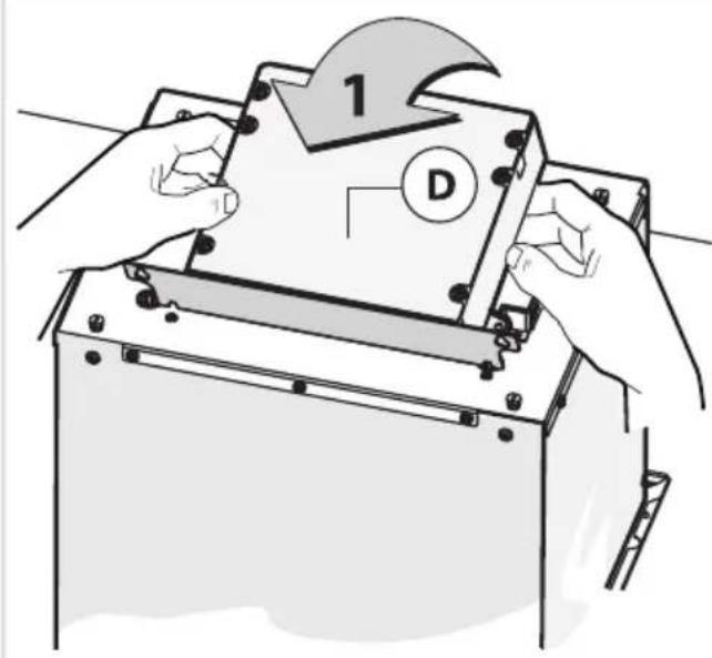
text_image
1 D6
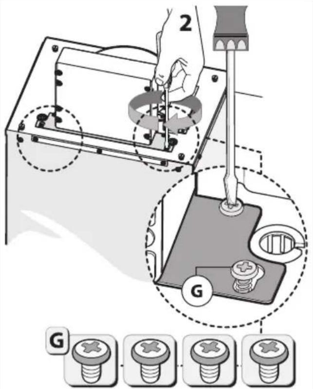
text_image
2 G G7
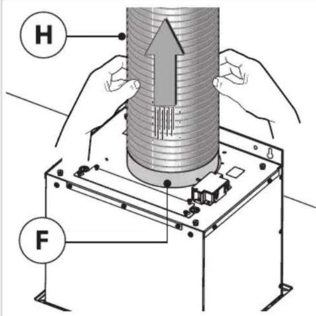
text_image
H F8
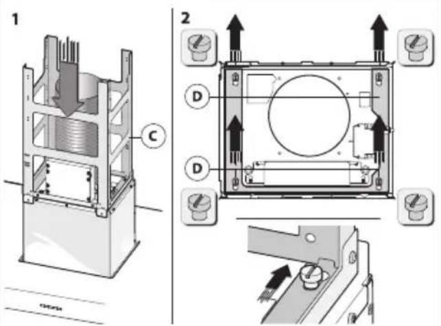
text_image
Technical diagram showing cross-sectional views of a mechanical device with labeled components and directional arrows indicating assembly or operation.9
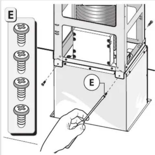
text_image
E E10
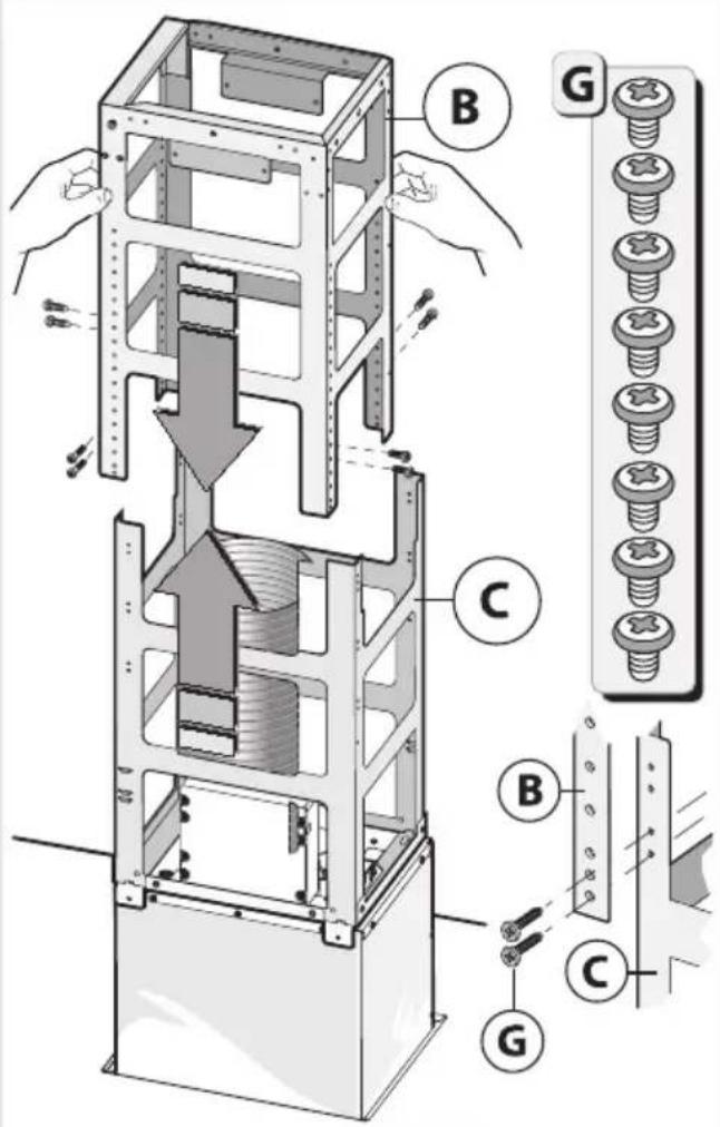
text_image
Technical diagram of a mechanical assembly with labeled parts (B, C, G) and directional arrows indicating movement or force.11
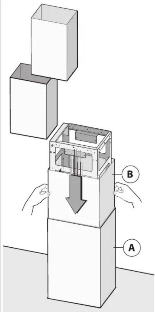
text_image
Diagram illustrating a mechanical assembly with labeled components A and B, showing a downward force on the internal structure.12
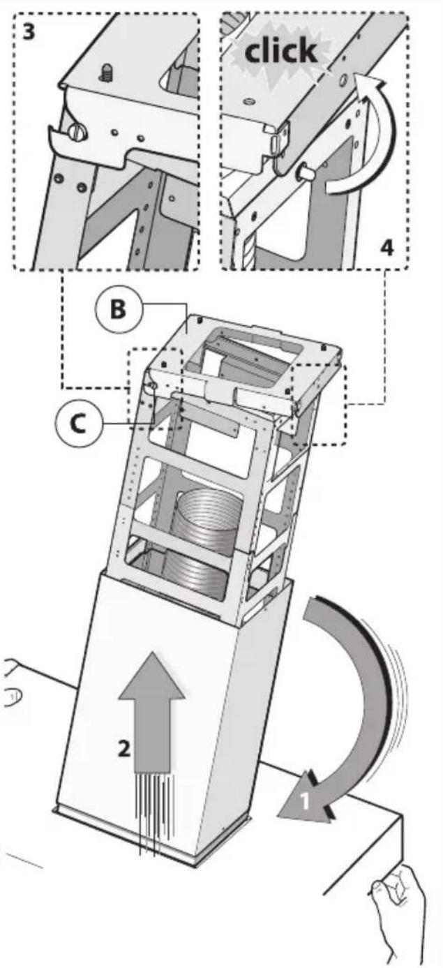
text_image
3 click 4 B C 2 113
text_image
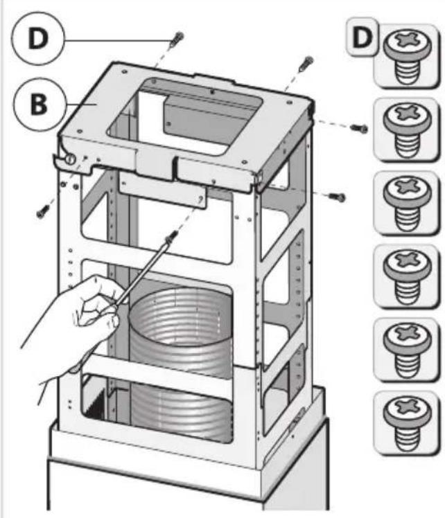
Technical diagram of a mechanical device with labeled parts (D, B) and corresponding screw assembly diagrams.14
text_image
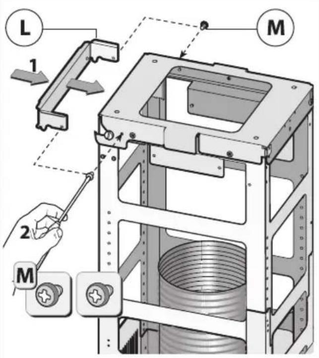
L 1 M 2 M15
text_image
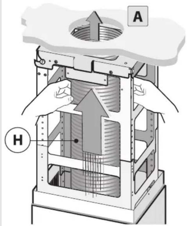
A H16
natural_image
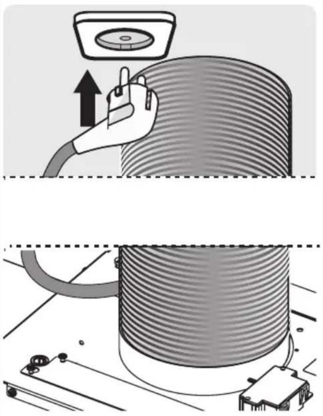
Illustration of a hand using a cable to lift a cylindrical component, with no visible text or symbols.17
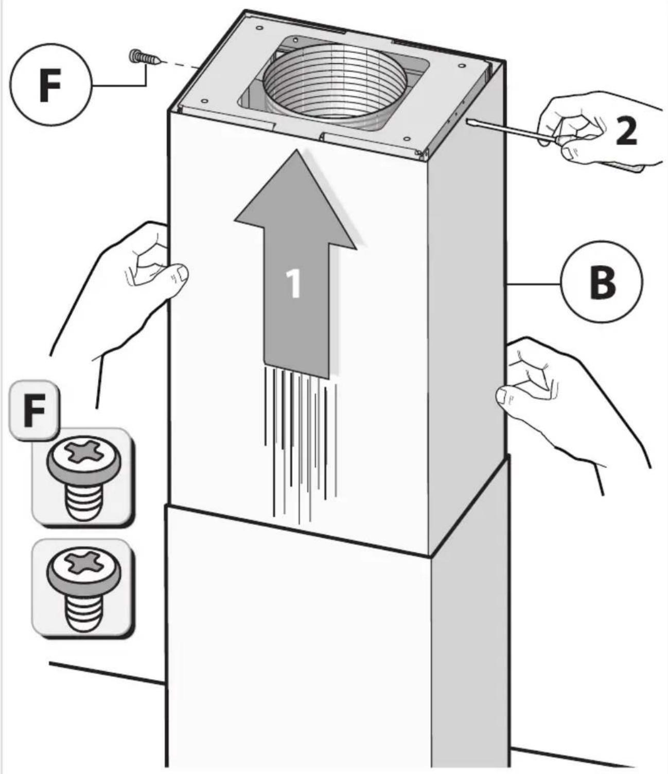
text_image
Warning symbol for a trash bin with crossed lines indicating no waste, and a black rectangle below.natural_image
Line drawing of a kitchen air conditioner unit (no text or symbols)GEBRAUCHSANWEISUNG
Abzugshaube
DE
WS9074MG
ES1074MG
natural_image
Two black rectangular icons: a plus sign and two gray circular indicators with icons for smart devices (no text or symbols)natural_image
Simple black-and-white graphic with a white semicircular shape and radial lines on a dark background (no text or symbols)natural_image
Simple circular graphic with a white semicircle inside a dashed border on a dark background (no text or symbols)natural_image
Simple white circular icon with a lightning bolt inside, on a dark background (no text or symbols)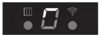
text_image
Digital display showing a grid, '0', and Wi-Fi icons on a dark backgroundWLAN/ConnectLife-App
natural_image
Three technical diagrams showing structural components of a ceiling frame, with no visible text or symbols.flowchart
graph TD
    A["Top Row: Column with Vertical Bars"] --> B["Bottom Row: Column with Vertical Bars"]
    B --> C["Top Row: Column with Unrolled Bars"]
    C --> D["Unrolled Section: Column with Unrolled Bars"]
    D --> E["Top Row: Column with Unrolled Bars"]
    E --> F["Unrolled Section: Column with Unrolled Bars"]
    F --> G["Top Row: Column with Unrolled Bars"]
    G --> H["Unrolled Section: Column with Unrolled Bars"]
flowchart
graph TD
    A["警告"] --> B["操作步骤1"]
    B --> C["操作步骤2"]
    C --> D["操作步骤3"]
    D --> E["操作步骤4"]
    E --> F["操作步骤5"]
    F --> G["操作步骤6"]
    G --> H["操作步骤7"]
    H --> I["操作步骤8"]
    I --> J["操作步骤9"]
    J --> K["操作步骤10"]
    K --> L["操作步骤11"]
    L --> M["操作步骤12"]
    M --> N["操作步骤13"]
    N --> O["操作步骤14"]
    O --> P["操作步骤15"]
    P --> Q["操作步骤16"]
    Q --> R["操作步骤17"]
    R --> S["操作步骤18"]
    S --> T["操作步骤19"]
    T --> U["操作步骤20"]
    U --> V["操作步骤21"]
    V --> W["操作步骤22"]
    W --> X["操作步骤23"]
    X --> Y["操作步骤24"]
    Y --> Z["操作步骤25"]
Beleuchtung
⚠️ WARNING!
natural_image
Isometric technical diagram of a mechanical assembly with directional arrows indicating movement or force (no text or symbols present)2
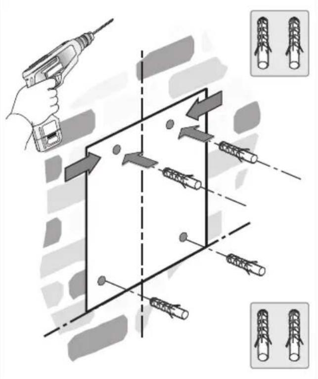
text_image
Diagram illustrating a 3D mechanical assembly with tool, arrows indicating movement, and two inset images showing cylindrical components.3
text_image
Technical diagram illustrating a mechanical assembly with labeled components and directional arrows indicating process steps.
text_image
Diagram illustrating a mechanical assembly with labeled parts and a hand holding a tool, accompanied by an inset showing screw thread arrangement.Installation
4
text_image
Technical diagram showing mechanical assembly with screws and a magnified inset of a threaded component with directional arrows.5
text_image
1 D6
text_image
2 G G7
text_image
1
text_image
Technical diagram showing mechanical assembly with labeled component '2' and directional arrow
text_image
3 3 mm8
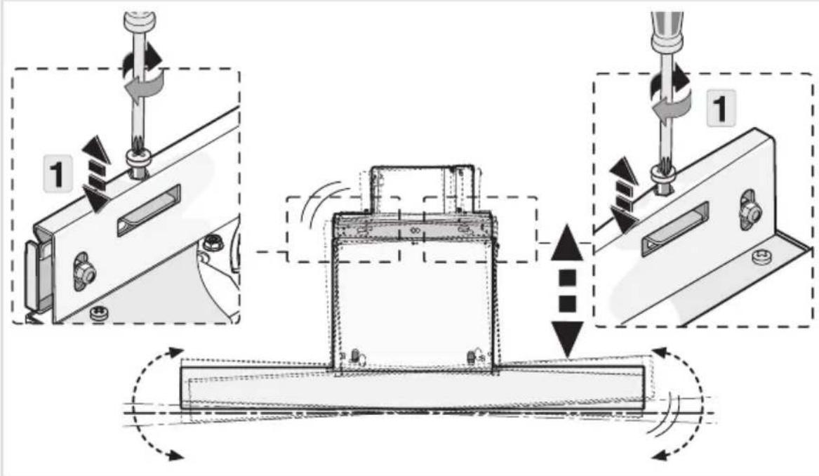
text_image
Technical diagram illustrating mechanical assembly steps with labeled components and motion indicators9
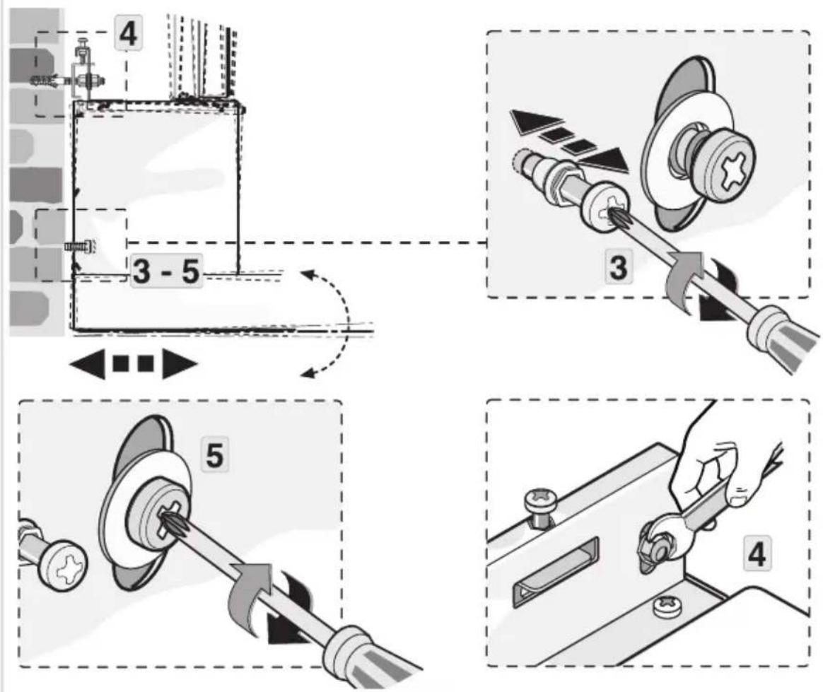
text_image
Technical diagram illustrating four different mechanical assembly steps with numbered instructions and labeled components.10
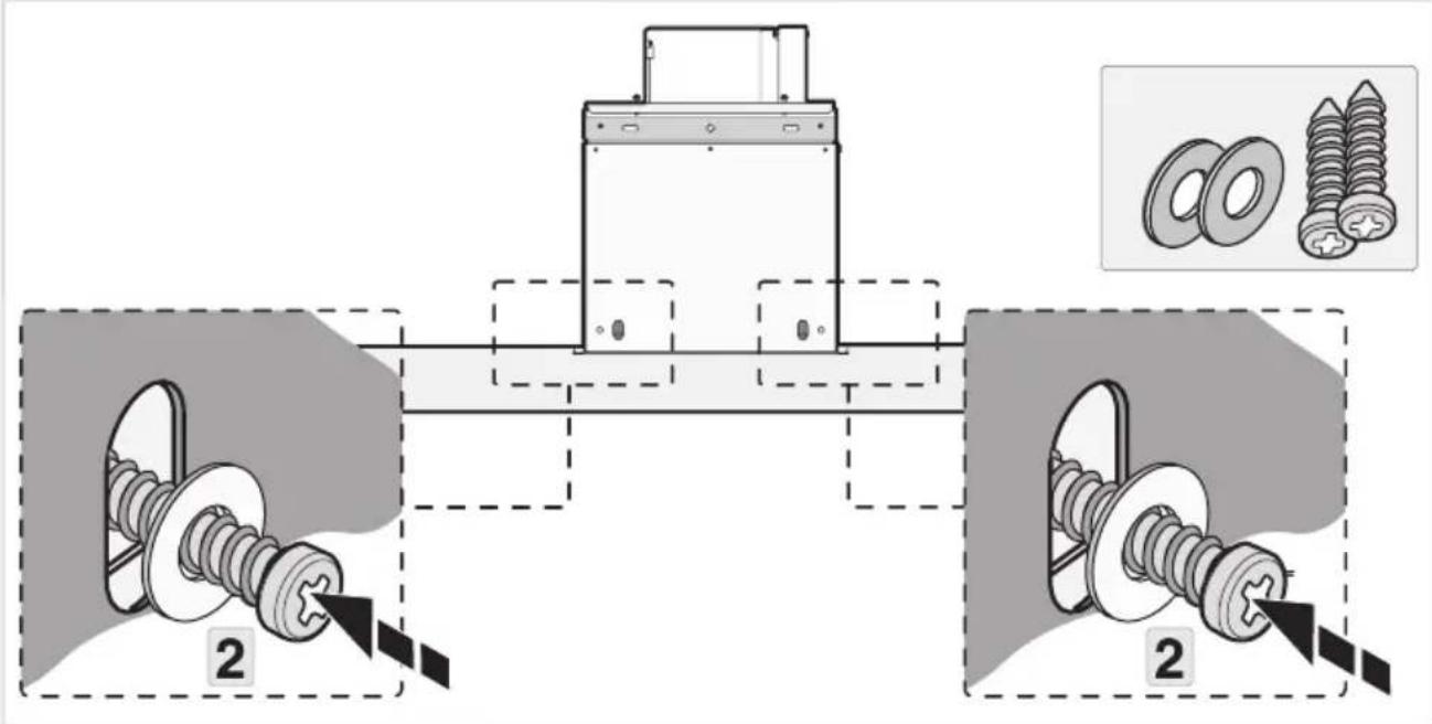
text_image
Technical diagram showing mechanical assembly with two labeled components and a close-up of screw parts, including inset images of washers.11
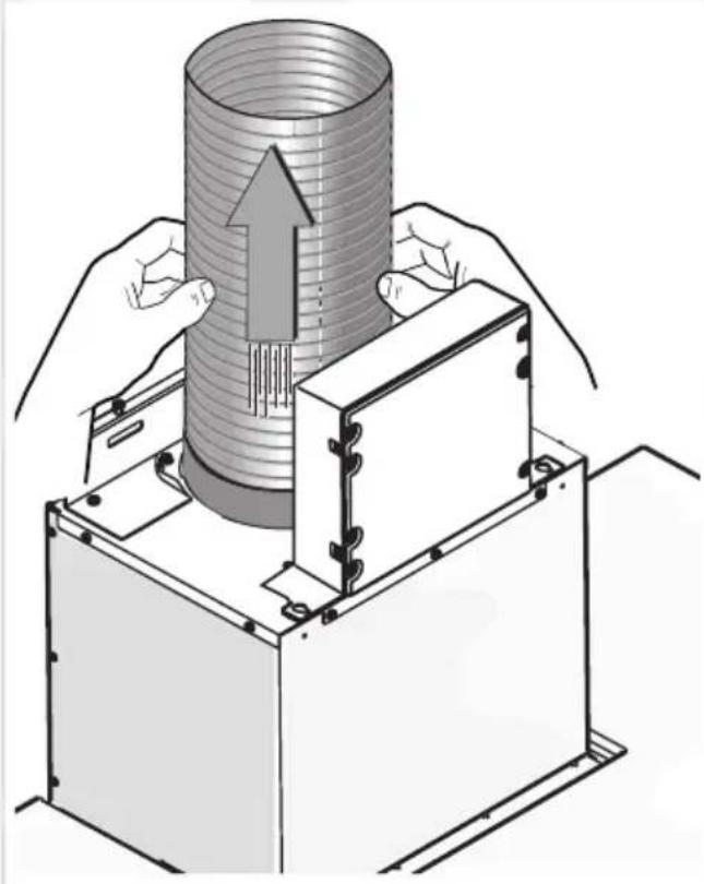
natural_image
Illustration of hands operating a cylindrical device with an upward arrow, no text or symbols present12
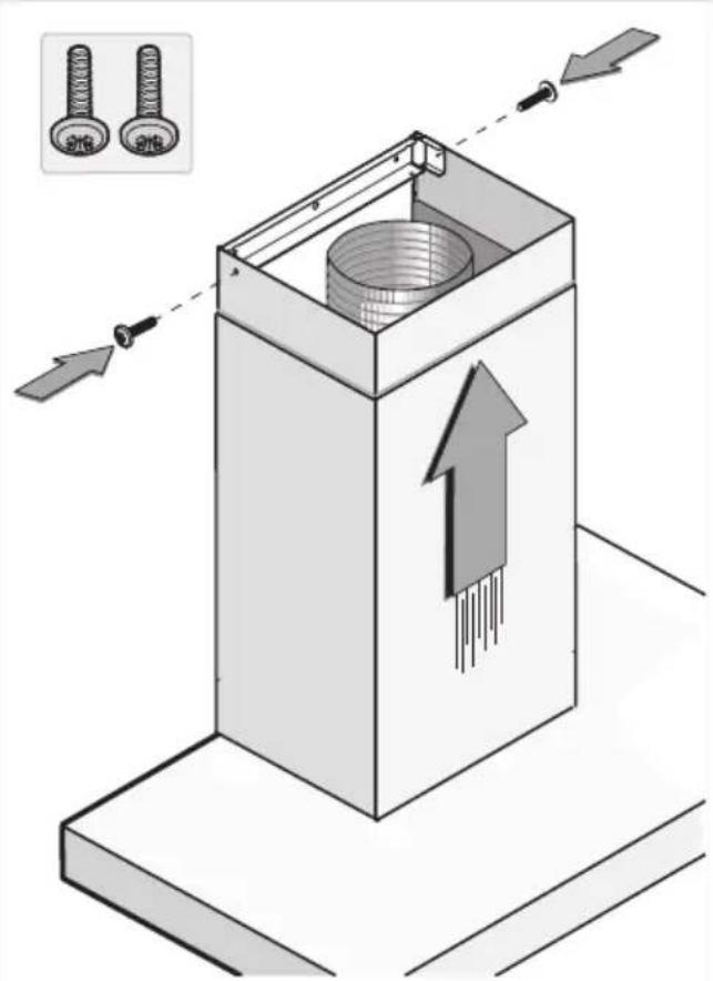
text_image
Technical diagram showing a mechanical component with arrows indicating assembly or movement, and inset images of two bolts labeled 'S16' and 'S26'.Inselhauben
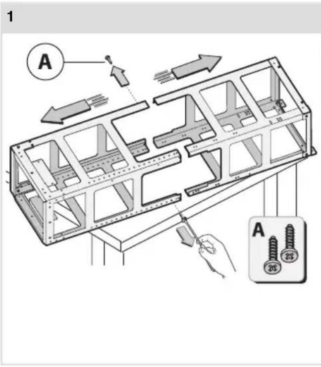
text_image
1 A A 28 23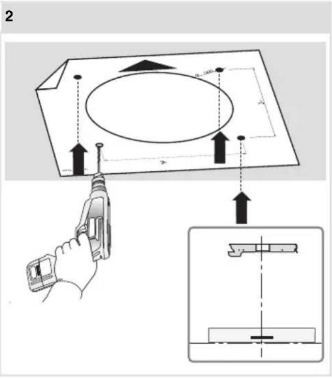
text_image
2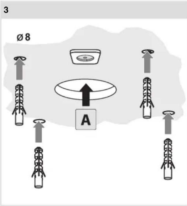
text_image
3 Ø 8 A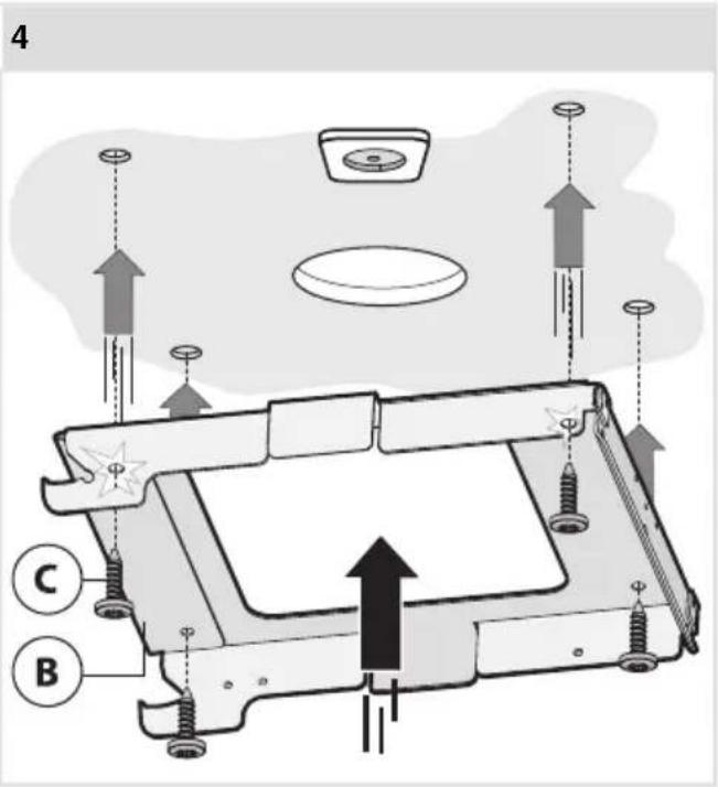
text_image
4 C B5
text_image
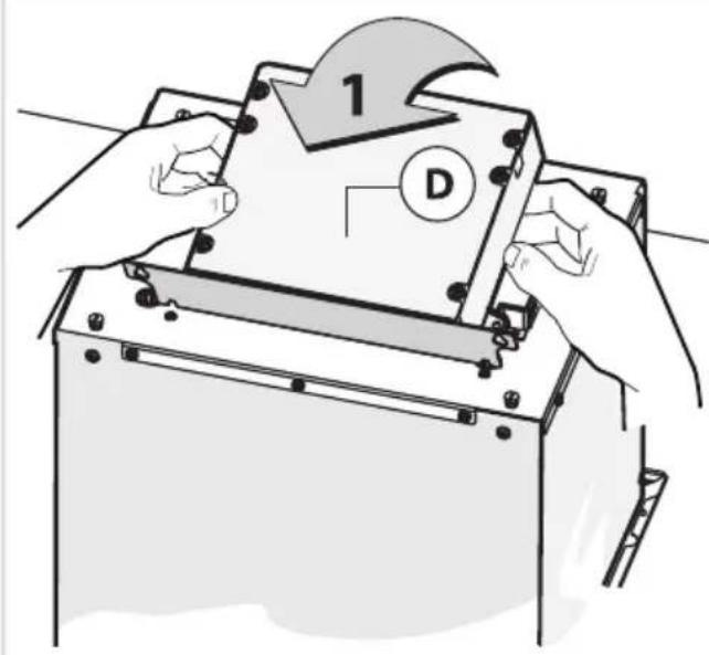
1 D6
text_image
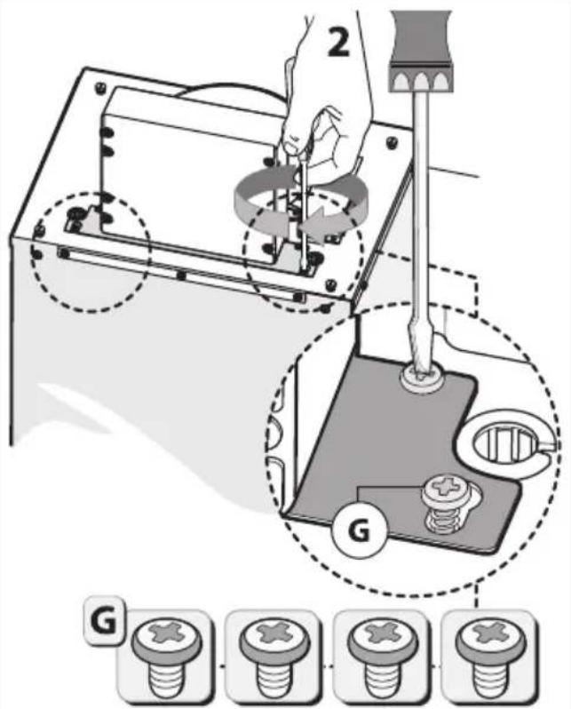
2 G G7
text_image
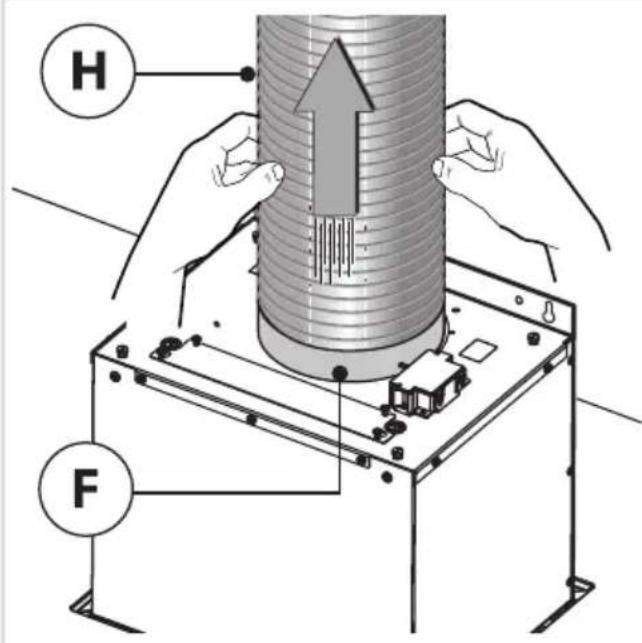
H F8
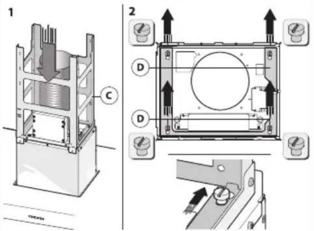
text_image
Technical diagram showing cross-sectional views of a mechanical device with labeled components and directional arrows indicating assembly or movement.9
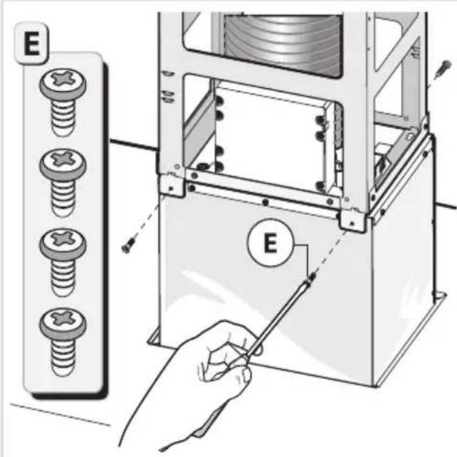
text_image
E E10
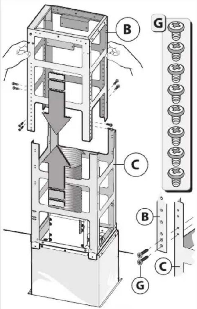
text_image
Technical diagram of a mechanical assembly with labeled parts (B, C, G) and directional arrows indicating movement or force.11
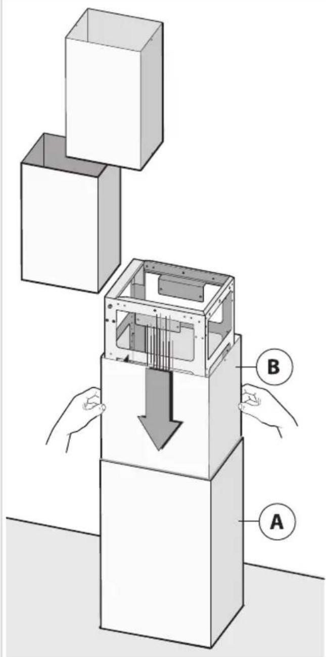
text_image
Diagram illustrating a mechanical assembly with labeled components A and B, showing a downward force on the internal structure.12
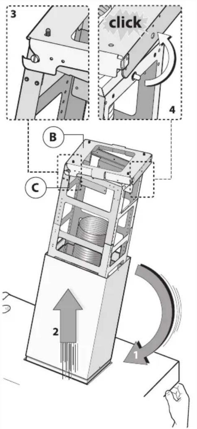
text_image
3 click 4 B C 2 113
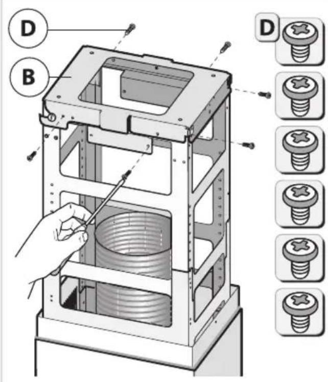
text_image
Technical diagram of a mechanical device with labeled parts (D, B) and corresponding screw assembly diagrams.14
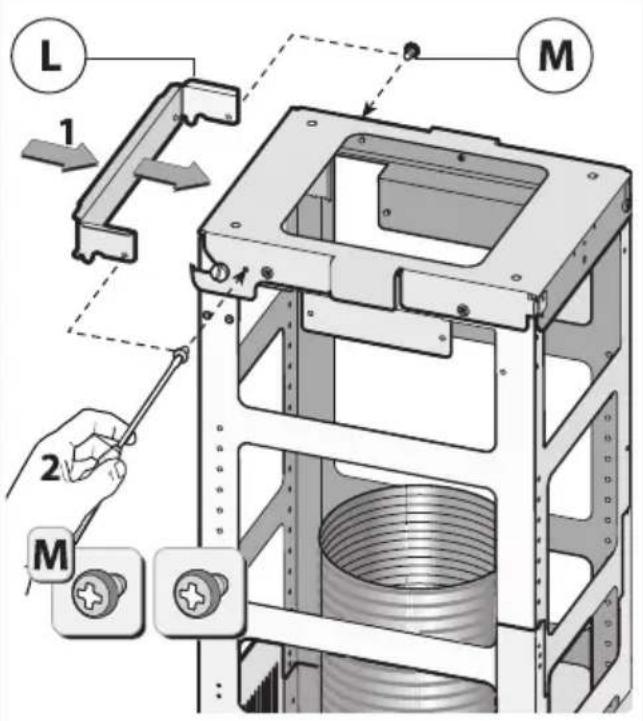
text_image
L 1 M 2 M15
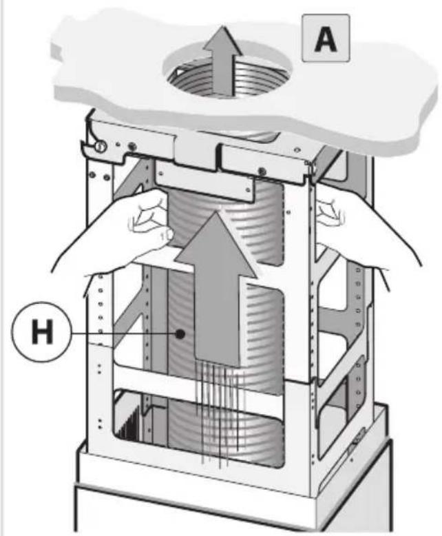
text_image
A H16
natural_image
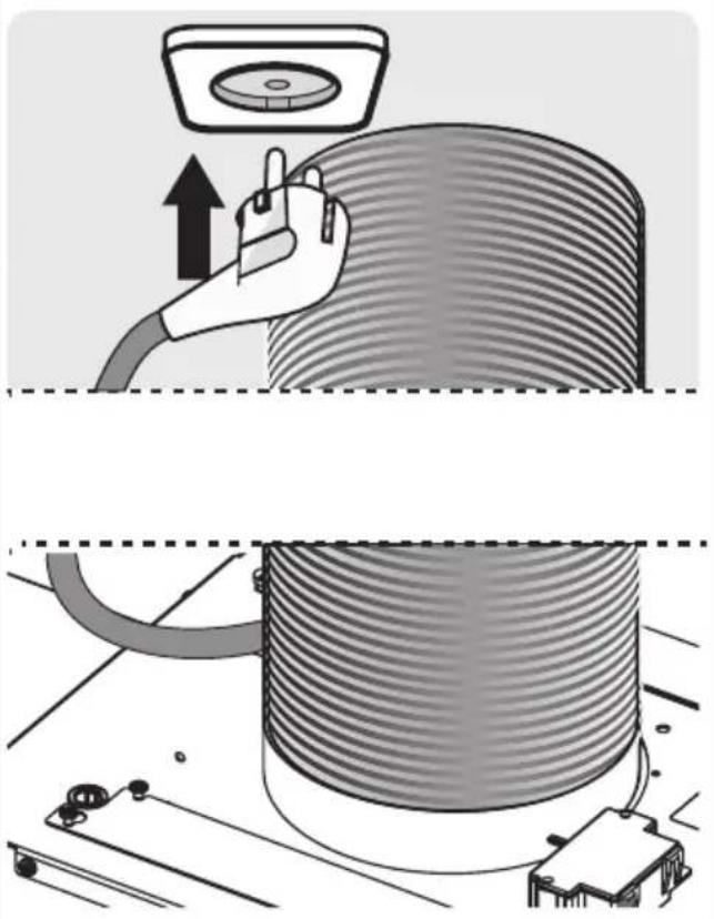
Illustration of a hand using a cable to press down a cylindrical component, with no visible text or symbols.17
text_image
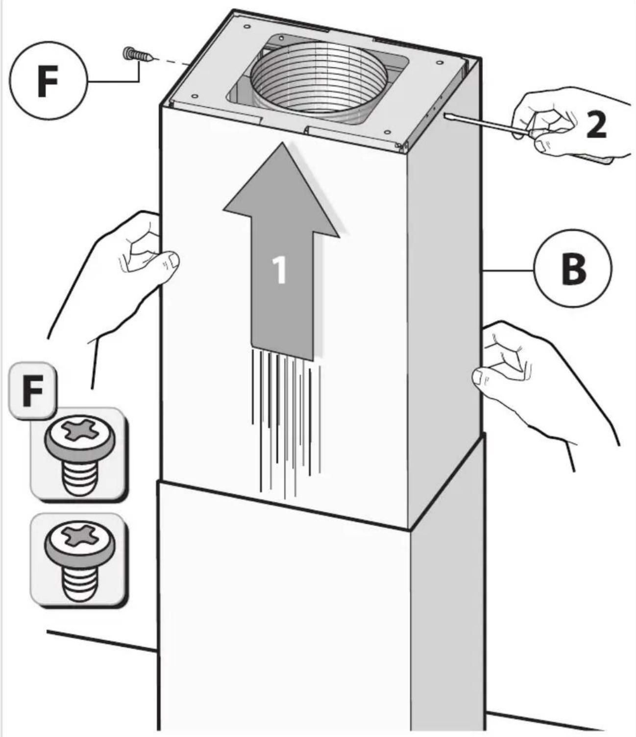
Warning symbol for a trash bin with crossed lines indicating no waste or discharge, and a black rectangle below.natural_image
Line drawing of a kitchen air conditioner unit (no text or symbols)INSTRUCTIONSFORUSE
Cookerhood
EN
WS9074MG
ES1074MG
Contents
3Pictogramsused......
4Safety......
4.....Replacingtheodour/particulatematters...
7YouPc&kerhood....
7Dearcustomer!......
8Descriptionuserinterface......
8Cookerhoodfunctions......
9Operation....
9Switchingextractiononandoff......
9Switchontheboostsetting......
9Switchingonautomaticdelayedshut-off.....
10Switchingthelightonandoff......
10Changingthecolourtemperature......
10Recirculationuse......
10Switchingontherecirculationfunction......
10Switchofftherecirculationfunction......
11 CleTipA for energy-efficient cooking with .....
11 Activordede....
12
13Wi-Fi-connectivity......
13Wi-Fi/ConnectLife-app......
17Maintena
17Cleaning.
18
19Lighting...
20Technica
20EUProduc
21EUProduc
21Compliant
22Installatic
22......
24Preparatic
24Electrical
25Appliance
26Built-in.....
37Environn
37
37Disposalo
38Yournote
Making the connection between cookerhood and hob....
The following symbols are used throughout the manual, and they have the following meanings:

INFORMATION!
Information, advice, tip, or recommendation

WARNING!
Warning-general danger

ELECTRICSHOCK!
Warning-dangerofelectricshock

HOTSURFACE!
Warning-dangerofhotsurface

DANGEROFFIRE!
Warning-dangeroffire
It is important that you carefully read the instructions.
WARNING!
READCAREFULLYANDKEEPITFORFUTUREREFERENCE!
Safeuse
- This appliance is only designed for household use.
- CAUTION: Accessible parts may become hot when used with cooking appliances.
- This appliance can be used by children aged from 8 years and above and persons with reduced physical, sensory or mental capabilities or lack of experience and knowledge if they have been given supervision or instruction concerning use of the appliance in asafeway and understand the hazards involved.
- Donotallowchildrentoplaywiththeappliance.
- Donotallowchildrentocleanormaintaintheapplianceunless supervised.
•Alwaysprovideadequateventilation!
- Thereshallbeadequateventilationoftheroomwhentherange hoodisusedatthesametimeasappliancesburninggasorother fuels.
- Whentherangehoodandappliancesuppliedwithenergyother thanelectricityaresimultaneouslyinoperation,thenegative pressureintheroommustnotexceed4Pa(4×10 -5 bar).
- Localregulationsconcerningthedischargeofairhavetobe fulfilled.
- Neveruseapressurecleanerorsteamcleanertocleanthe appliance.
ELECTRICSHOCK!
Avoidtheriskofelectricshock;makesuretheapplianceis switchedoffbeforecleaningtheappliance.
- Onlyusetheapplianceinsidethehome.
- Donotusethecookerhoodifthegreasefilterhasnotbeenfitted properly!
- Donotleanagainstthecookerhood.
- Neverusethecookerhoodasaworkingsurfaceunlessthisis indicatedexplicitly.
- Grease and oil are inflammable when overheated. Remain in the cooking area when preparing meals.
- Topreventhotfatfromcatchingfire,youshouldonlydeep-fry undercontinuoussupervision.
- Thecookerhoodshouldbecleanedregularlybothontheoutside aswellastheinside(atleast1xpermonth).Insufficientcleaning oradelayinthereplacementoffilterscancauseafirehazard.
- Cleanthefiltersontime.
- Thegreasefilterscanbecomehotduringuse.Aftercookingwait atleast30minutesbeforecleaning.
- Plesenote!Intensiveusecanleadtocondensationonthe cookerhood.Condensationissimpletoremovewithadrycloth.
- Followtheinstructionsinthemanualforcleaningorreplacingthe greasefiltersand/orcarbonfilters!

DANGEROFFIRE!
Thereisariskoffireiftheinstructionsforcleaningorreplacing greasefiltersand/orcarbonfiltersarenotfollowed.
Throughgreasedepositsinthemetalgreasefilter.Neverwork withopenflameundertheappliance(eg.flambéing).Alwaysuse theappliancewiththemetalgreasefilter.Cleanthegreasefilter regularly.
Throughoverheatedfatoroil. Neverextinguishafirewithwater; alwaysuseafireblanket, lidorplate.
- The appliance may have sharpedges; please be careful during cleaning.
Safety
- ThelightemittedbyLEDlightsisverydazzlingandcandamage theeyes.DonotlookdirectlyintotheswitchedonLEDlightsfor longerthan100seconds.
- Whenwashinggreasefiltersinthedishwasheritisrecommended touseashort,non-intensiveprogramme.Checkthegreasefilter afterwashinginthedishwasherforwear(loosematerial).Wear canoccurasaresultoffrequentwashing.Ifloosematerialis visible,replacethefiltersinordertopreventthisloosematerial fromendingupinthefoodthatiscooked.
- Donotusetheapplianceintemperaturesbelow5°C.
Dearcustomer!
Pleasereadtheoperatinginstructionsbeforeuse. Theyincludegeneraltips,informationaboutthe settingsandadjustmentsyoucanmake,andthebestwaytotakecareofyourappliance.
TIP!
You can find them most recent version of the instructions for use on our website.
Enjoyyourcooking!
Descriptionuserinterface
text_image
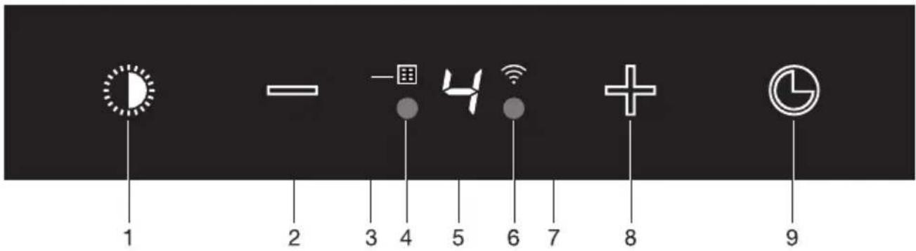
1 2 3 4 5 6 7 8 9- Switchingon/offanddimmingthelighting
- Reducingairextractioncapacityandswitchingoff
- Greasefilterandcombifiltercleaningindicator
- Proximity sensor
- Displaystatus
- Proximity sensor
7.Wi-Fi - Switching on and increasingairextractioncapacity
9.Switchonautomaticdelayedshut-off
Cookerhoodfunctions
Recirculation
Ifitisnotpossibletodischargetheairtotheoutsideviaanexhaustduct,youcanchoosetofilter theextractedairandblowitbackintothekitchen,therecirculationsystem.Whenusingthe recirculationsystem,theairafterpassingthegreasefiltersispurifiedbyacombi-filterandblown backintothekitchen.Thissystemisenergyefficientbecausenowarmairisdischargedtothe outside.
If you usethere circulationsystem, you should activate the 'Filtercleaning indicator' described in the 'Maintenance' paragraph.
Activemode
Theproximitysensordetectsauserstandinginfrontofthehoodandwillilluminatetheicons.
Automaticdelayedshut-off
Thetime-controlleddelayedshut-offensuresthatthelastcookingvapoursarestillextracted. Thedelayedshut-offmodeswitchesoffautomaticallyafter10minutes.
CleanAirfunction
TheCleanAirfunctionswitchonautomaticallyfor10minutesevery24hoursatthelowestspeed setting.
Switchingextractiononandoff
natural_image
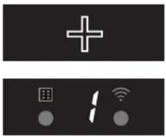
Two black rectangular icons: a white plus sign and two gray circular icons with icons for smart devices (no text or symbols)- Touchthe+(plus)key.
- Thecookerhoodwillswitchonatthelowestsetting.
- Touchthe+(plus)keyforahigherfansetting.Touchthe+(plus)keyfor2secondstoselectthehighestsetting(boost)(see'Switch ontheboostsetting').
- Touchthe—(minus)keytoselectalowersetting.
- Theextractionsettingcanbereadinthedisplay.
- Theextractionsettingcanbesetbetweenspeedslevel1to5.
- If the extraction setting is set at 1, you can switch to the cooker hood by touching the minus key.
- Touchthe—(minus)keyforatleast2secondstoswitchoffthe cookerhood.
Switchontheboostsetting
text_image
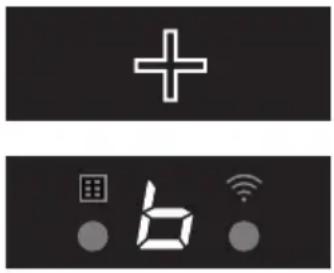
+ b- Touchthe+(plus)keyforatleast2seconds.
- The boost setting (setting 'b') is switched on for 10 minutes. Thedisplaywillflashduringthisperiod. Theoriginalextraction settingwillbereactivatedafterthisperiod.
- Shorttouchthe-(minus)keytoswitchofftheboostsetting.
NOTE!
Boostisnotavailableinrecirculationmode.
Switchingonautomaticdelayedshut-off

natural_image
Simple white pie chart icon on black background (no text or symbols)-
Touch the automatic delayed shut-off key.
-
Theautomaticdelayedshut-offindicatorwillflash.
-
Thecookerhoodwillswitchoffautomaticallyafter 10minutes.
-
Switchoffautomaticdelayedshut-offbytouchingarandomkey (exceptthelightingkey).
NOTE!
If the boost setting has been selected, the timer function cannot be activated.
Operation
Switchingthelightonandoff

natural_image
Simple circular graphic with a white half-circle and dashed border on black background (no text or symbols)- Shorttouchthelightingkey.
- Thelightingchangesfrommaximumtominimumstrengthand viceversa.
- Longtouchthelightingkeytosetthelightingstrength.
3.Shorttouchthelightingkeytoturnoffthelight.
Changingthecolourtemperature
Youcanadjustthelightingtemperature.
- Long touch the lighting key and simultaneously the – (minus) key to make the light 'colder' or the+(plus)keytoselecta'warmer'light.
Recirculationuse
NOTE!
Ondelivery, this cooker hoodissetforexhaustairtotheoutside. The hoodcanalsobesetto recirculationuse (the airisblownbackintotheroomafterfiltrationthroughgreasefiltersanda combi-filter).
WithanRMSkit(recirculationmodificationset), the air will first be cleaned by the grease filters, and then odours will be filtered by the combi-filter. The cleanedair is recirculated back into the kitchen.
Switchingontherecirculationfunction

- Continuouslytouchthetimerkeyandthelightingkeysimultaneously untilthefilterindicatorflashes3times.
• Thecookerhoodissetforrecirculationuse.

Switchofftherecirculationfunction
- Simultaneously shorttouch the timer key and the lighting key until the filter indicator stay on.
CleanAirfunction
text_image
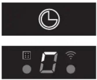
Digital display icons including pie chart, grid, and Wi-Fi symbols on black backgroundTheCleanAirfunctionallowsyoutofreshentheairinyourkitchenforamaximumof24hoursatlevel1.
-
Switchoffthecookerhood.
-
Touch the timer key for approximately 3 seconds.
- Thecookerhoodwillswitchonautmaticallyfor10minutes everyhouratthelowestspeedsetting.Duringextraction,the displaywillshowafast-moving'snake'.Whenthehoodswitches offafter10minutes,thedisplaywillshowaslow-moving'snake' untilthehoodswitchesonagainafter50minutes.
3.SwitchofftheCleanAirfunctioninthemeantimebytouchingarandomkey(anykeyotherthanthelightingkey).
Activemode
Theproximitysensordetectsauserstandinginfrontofthehoodandwillilluminatetheicons.
Disabletheactivemode
text_image
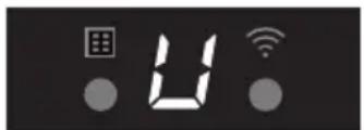
Digital display showing 'U' with grid icon, Wi-Fi signal, and circular buttons below- Simultaneouslytouchthe+(plus)keyandtimerkeyfor3seconds.
• Theactivemodeisdisabled.
• Thedisplayshowsastatic 'U'.
Enabletheactivemode
- Simultaneouslytouchthe+(plus)keyandtimerkeyfor3seconds.
• Theactivemodeisenabled. - Thedisplayshows3timesablinking‘U’.
Operation
Making the connection between cooker hood and hob
Tooperatethecookerhoodwiththehob,youmustmakeaconnectionbetweenthehobandthe hood.
Tomaketheconnection, the Connection setup mode of the cooker hood and the hob must be activated.
Seealsothemanualforthehob.Checkourwebsiteforthefullrangeofhobsthatcanbeconnected toyourcookerhood.
- The hood and lights must be switched off.
- Touchandholdsimultaneouslythe-(minus:keyandthe+(plus:keyfor3seconds.
- The lighting key, the + (plus) key, the – (minus) key and the timer key will flash simultaneously for a maximum of 3 minutes.
- On your hob, activatethepairingmodeintheusermenu(seethehobmanual)
• The connection to the hobis established.
- If the connection is successful, the cookerhood will return to standby.
NOTE!
When manually operating the hood in connection mode, the pairing will belost and must be paired again.
Wi-Fi/ConnectLife-app
The appliance is fitted with a Wi-Fi module that allows the appliance to connect to a mobile device such as a smartphone or tablet. It offers a monitor the appliance status via a mobile device.
NOTE!
Themonitoringfunctionviamobiledeviceshallnotbeusedtoreplacethepersonalsupervision ofthecookingprocessdirectlyontheappliance.
Requirements:
- To use the Wi-Fi connectivity of the appliance, the range of your Wi-Fi router must extend to the appliance. The appliance only supports 2.4GHz networks. If during the connection setup, your homenetwork is not shown, check their outersettings for 2.4GHz, that thenetwork is no hidden, and the signal is strong enough.
- Additionally, amobiledevicewithaninstalledConnectLife-appendaregistereduseraccount isrequired(seechapter'ConnectLife-app').

ConnectLife-app
The ConnectLife-app is available on the Apple App Store and Google Play Store. After pairing with the appliance, the app can be used to monitor the status of the appliance.
Gotowww.connectlife.io/getstartedtodownloadtheConnectLife-app,informationaboutthesystem, supportandavailablefeatures.Findadditionaloptionsunderwww.connectlife.io.
GettingstartedwiththeConnectLife-app
Get started with your ConnectLife-app in 3 easy steps. Please check as addition chapter "First steps to setup the Wi-Fi connectivity". More help under www.connectlife.io/getstarted.
1. Registration:
•InstalltheConnectLife-app.
- Starttheapp.
- Choose "Get Started" and follow the process.
- If you are already registered, use the "Sign In" option.
2.Addtheappliance:
- Intheapp:Goto"Appliances".
- Choose "Add Appliances" or touch the + (plus) key.
- Make sure Wi-Fi on the appliance is turned ON and the appliance is in Connection Setup Mode(seeasaddition'FirststepstosetuptheWi-Ficonnectivity').
- FollowtheinstructionsoftheConnectLife-app.
3.Startcooking:
Congratulations, you can now start using ConnectLifetogether with your appliance.
FirststepstosetuptheWi-Ficonnectivity:
Within the following steps, the "Connection setup" is performed:
- Checkthe "Requirements" as described above.
- The hood and lights must be switched off.
- Touchandholdsimultaneouslythe-(minus)andtimerkeyfor 3secondstoentertheWi-Fimenu.The'Light'iconwillbeturned off.
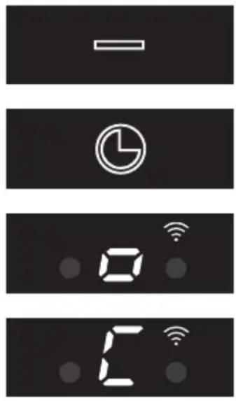
- Touchandholdsimultaneouslythe-(minus)andtimerkeyfor 3secondstoturnonWi-Fi.'o'willblink3times.Wi-Fisymbolwill blink.
- Touchandholdsimultaneouslythe+(plus)andtimerkeyfor 3seconds. Thedisplaywillshowan'C'. Confirmwiththetimerkey tostartthe'Connectionmenu'. Thismodewillbedisabled automaticallyafter5minutes.
- In the ConnectLife-app, select the option 'AddAppliance' and follow the instructions.
- If the ConnectLife-app does not connect to the device, wait 10 minutes and repeat the steps described.
- Optionally: Whentheprocesswassuccessful, and you want topair another user, you can us the Pairing mode of the Wi-Fimenu and the Pairing or Discovery option of the Connect Life-app.

INFORMATION!
TroubleshootquicklybyturningtheWi-Fimoduleoffandonagain.Youcanfindmorehelpinthe "Wi-Fitroubleshooting"section.
DependingontheWi-Fistate,thereare1to3optionsavailableinthemenu:
•TheConnectionSetupMode
•ThePairingMode
- Remotecontrolmode
If more than 1 option is available then us the + (plus) and - (minus) keystotoggle between the options.
ConnectionSetupMode
The appliance must be connected to the Cloud for the application to monitor and control the appliance remotely.
'C' is shown on the display. Touch the timer key to enable 'Connection Setup Mode'. The Wi-Fi symbol willflash.Thismodewillbedisabledautomaticallyafter5minutes.
PairingMode
Bypairing,yougainmonitoringfunctionalityinsidetheConnectLife-app.Duringpairing,youconnect yourappliancetoyourConnectLifeuseraccount.
PairingModeisonlyavailableiftheWi-Ficonnectivitysetuphasbeenperformed.
'P' is shown on the display. Touch the timer key to enable 'Pairing mode'. The Wi-Fi symbol will flash. Thismodewillbedisabledautomaticallyafter3minutes.
On the ConnectLife-app, use the 'Pairing' or 'Discovery' option of the ConnectLife app to pair another user.
Remotecontrolmode
Tochangefunctionsettingsremotely,theappliancemustbeswitchedon,andtheConnectLife-app mustbeenabled.
'c' is shown on the display. Remote control mode is only available if the Wi-Fi connectivity setup has been performed. Touchthetimerkeytoenable'Remotecontrol'.
Blinking'c': Remotecontrolisenabled.
Static'c': Remotecontrolisdisabled.
To close the Wi-Fi menu, touch and hold the – (minus) key for 3 seconds. If no key is touched within 10 minutes, the Wi-Fimenu will be switched off automatically; the hood will be back in standby mode.
Wi-Fimenu
To access the Wi-Fi menu, the hood must be on standby. Touch and hold simultaneously the – (minus) keyandtimerkeyfor3seconds.DependingontheWi-Fistate,thereare1to3optionsavailablein the menu: 'C', 'P', and 'c'. If more than 1 option is available, then use the + (plus) and – (minus) keys totogglebetweentheoptions.Confirmtheselectedoptionbytouchingthetimerkey.
SwitchingonWi-Fi:
•Thehoodmustbeswitchedoff.
- Touch and hold simultaneously the – (minus) and timer key for 3 seconds to enter the Wi-Fi menu. The 'Light' icon will be turned off.
- Touch and hold simultaneously the – (minus) and timer key for 3 seconds to turn on Wi-Fi. 'o' willblink3times.Wi-Fisymbolwillblink.
SwitchingoffWi-Fi:
•Thehoodmustbeswitchedoff.
- Touch and hold simultaneously the – (minus) and timer key for 3 seconds to enter the Wi-Fi menu. The 'Light' icon will be turned off.
- Touch and hold simultaneously the – (minus) and timer key for 3 seconds to turn off Wi-Fi. 'o' will bestatically lightened. The Wi-Fisymbolwillturnoff.
DisplayingtheWi-Fistatus:
- Wi-Fimoduledisabled:Wi-Fisymbolnotdisplayed.
- Configurationinprogress:Wi-Fisymbolflashes.
- Connectedtohomenetworkrouter:Wi-Fisymbolflashes.
- Connectedtohomenetworkrouterandcloud:Wi-Fisymbolcontinuouslylit.
Wi-Fitroubleshooting
| SolutionPossiblecauseSymptom | ||
| Wi-Fiturnedoff.Wi-Fiiconnotsh | SwitchonWi-Fi(see'Switchingon Wi-Fi'). | |
| Homenetworkissues.Wi-Fisetup | Chieldhatyourhomenetworksignal isstrongandinternetconnectionis working. | |
| Homenetworkisnot displayedduringconnection setup. | Thehomenetworkisnoton 2.4GHz,thenetworkis hidden,orthesignalstrength istoowek. | Pleasecheckthenetworksettings.Ensurea2.4GHzandvisiblenetwork.Ifthesignalistoowek,trytomovethe networkrouterclosertotheappliance. |
| Applianceisshown disconnectedonthemobile app. | Wi-Fiisdisabledorhome networkissues. | EnsurethatWi-Fiisenabledandthe internetconnectioninyourhome networkisworking.Repeatthe connectionsetupifnecessary. |
| Differentcauses.OtherWi-Fipro | FiletdisabletheWi-Fiandenableit again.Checkthattheinternet connectioninyourhomenetworkis working.Repeattheconnectionsetup ifnecessary.Furthertroubleshootingavailableon www.connectlife.ioorcontactthe servicedepartment. |
Cleaning
WARNING!
Important!Forallmaintenance,first,switchoffthemainspowertothecookerhoodbypulling theplugoutofthesocketorbyturningoffthehome'smasterswitch.Thehoodneedstobe cleanedregularly,bothinsideaswellasoutside(atleastasoftenasthegreasefilter).
Donotuseabrasivecleaningproducts.Donotusealcohol!
If the instructions regarding cleaning the appliance or replacing the filters are not followed, this can cause a fire. These instructions must be followed! The manufacturer is not liable for damage to the hood or fired damage resulting from incompetent maintenance or from non-adherence to the safety instruction above.
Cookerhood
Cleanthecookerhoodwithsoapywaterandasoftcloth.
Thenrinsewithcleanwater.Donotuseaggressivecleaningagentssuchascausticsoda.Thecooker hoodfinishstaysingoodconditionifitisbuffedperiodicallyfollowingtheapplicationofwax.
NOTE!
Stainlesssteelcookerhoods
Donotusescouringpadsorotherabrasivecleanersonstainlesssteelcookerhoods.Finishwith anon-abrasive,non-polishingagentandbuffthestainlesssteelinthedirectionofthegrain.
Filtercleaningindicator
Thefilterindicatorwilllightafter30operatinghours.
• The greasefilters should then be cleaned.
- Metalgreasefiltersshouldbecleanedonceamonth(orwhenindicatedbythefiltercleaning indicator)usinganeutralcleaningagent,eitherbyhandorinthedishwasheronashort, low-temperatureprogram.
- Place the grease filters with the openings facing downwards in the dishwasher so the water can drainoutofthefilter.Aluminiumgreasefiltersbecomedullasaresultofdishwashercleaning agents.Thisisnormalanddoesnotaffecttheworking.Allowthefilterstodrainwellbefore replacing.
- Reset the memory by long touching the – (minus) key until the filter indicator goes off.
Maintenance
Removingcassettefilter
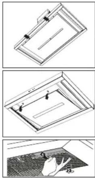
natural_image
Three technical diagrams showing structural components of a ceiling frame, with no visible text or symbols.- Switchoffthemotorandlighting.
2.Pushinthelatchesandopenthepanel. - Openthefilter'saccesslatch.Supportthefilterwithyourhand.
- Removethefilterfromthehood.
Insertingcassettefilter
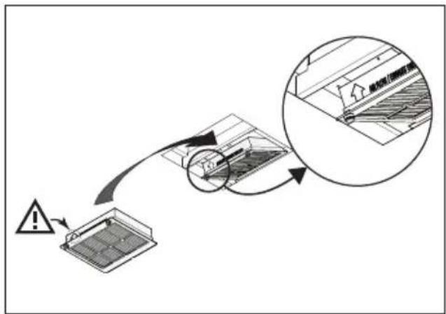
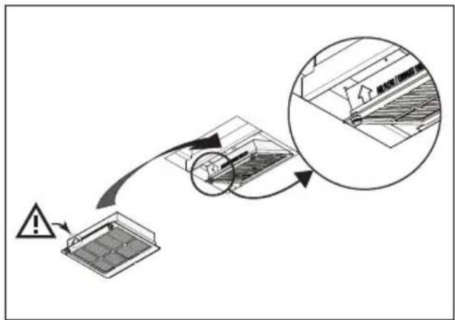
Thefiltershouldbeplacedwiththelockingmechanismonthefront. Openthefilteraccesslatch. Thenotchesatthefrontofthefilterwillthenslotin.Holdtheaccesslatchinthispositionwhenplacing thefilters.
- Slotthenotchesatthebackofthefilterinthespeciallydesignedopeningofthecookerhood.
- Tiltthefilterupwards.
- Releasethefilteraccesshatch. Thenotchesatthebackofthefilterwillextendoutwardsand slotintothespeciallydesignedopeningsofthecookerhood.
Thefilterisnowinpositionagain. - Presstheglassplatefirmlyinthesealagain(youwillhearaclick).
WARNING!
Theglassplatecanberemovedforcleaning. Twooplearerequiredwhenremovingtheglass plate(duetoitsweight)!
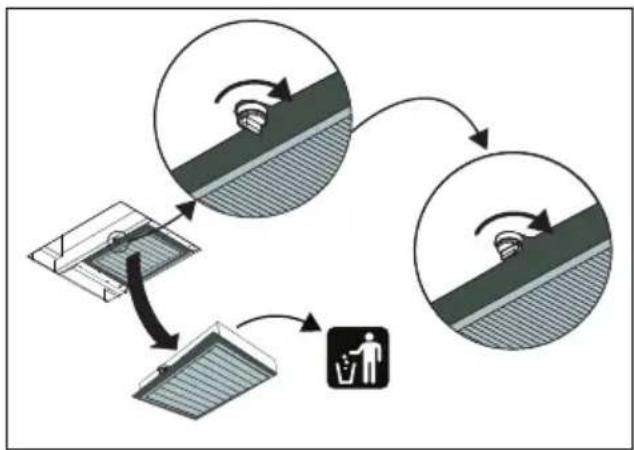
Replacingtheodour/particulatematters(PM2.5)filter
Theodour/fineparticlefiltermustbereplacedannually(orindicatedbytheodour/fineparticlefilter cleaningindicator).
Thefilterindicatorwillflashafter360operatinghours.
- Removethescrewatthefrontsecuringthefilterholderbyturningitanti-clockwise.
- Removethefilterholderwiththefilteroutofthehood.
- Removetheoldfilteranddisposeofitwithyourresidualwaste.
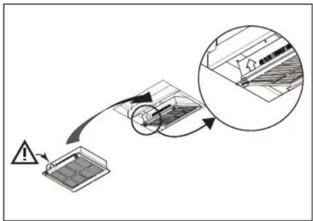
- Replacethenewfilterintheholder. Note: The arrowontheside indicate the airflow direction.
-
Replacethefilterholderbyfirstinsertingthebackintothenotches.
-
Re-tightenthefilterholder.
-
Resetthememorybylongtouchingthe-(minus)keyuntilthefilterindicatorgoesoff.
NOTE!
- Morenoiseisproducedwhenodourfiltersareusedthanwhenthecookerhoodisusedwithanexhaustvent.
- Odourfiltersfunctionoptimallyatalowermotorspeed.Consequently,youshouldavoidthe intensivesettingasmuchaspossible.
CAUTION!
Thesaturationofthefilterdependsontheintensityofuse,themannerofcookingandtheregularity withwhichthegreasefiltersarecleaned.
flowchart
graph TD
    A["Top Row: Top Row with rotation arrow"] --> B["Bottom Row: Bottom Row with rotation arrow"]
    B --> C["Top Row: Top Row with waste bin icon"]
    C --> D["Bottom Row: Bottom Row with waste bin icon"]
    D --> E["Top Row: Top Row with waste bin icon"]
    E --> F["Top Row: Top Row with waste bin icon"]
flowchart
graph TD
    A["警告"] --> B["操作"]
    B --> C{检查}
    C -->|是| D["处理"]
    C -->|否| E["返回"]
    D --> F["完成"]
    style A fill:#f9f,stroke:#333
    style F fill:#ccf,stroke:#333
Lighting

WARNING!
ThehoodisfittedwithLEDlights.Anauthorizedtechnicianmustreplacethese.Donotattempt toreplacetheLEDlightsyourself.
EUProductSheet
Datadeterminedaccordingto:
StandardEN61591andCommissionRegulations(EU)no.65/2014and(EU)no.66/2014.
| ES1074MGWS9074MG | ||
| ATAGATAGTrademark | ||
| ES1074MGWS9074MGTypeofmor | ||
| hood)[kWh/a] | 25.323.8AnnualEnergyConsumpti | |
| Energyefficiencyclass | A++ | A++ |
| hood)[%] | 38.439.2FluidDynamicEfficiency(F | |
| AAFluidDynamicEfficiencyclass | ||
| hood)[lux/W] | 53.853.8LightingEfficiency(LE | |
| AALightingEfficiencyclass | ||
| hood)[%] | 89.489.4GreaseFilteringEfficiency | |
| BBGreaseFilteringEfficiencyclass | ||
| [m^3/h] | 321/444322/439Airflowatminimum | |
| ^3/h] | 783761Airflowatintensiveorboosts | |
| Airborne acoustical A-weighted sound power emissions atminimum andmaximumspeedinnormaluse[dB(A)] | 46 / 53 | 46 / 53 |
| Airborne acoustical A-weighted sound power emissions atintensiveorboostsetting[dB(A)] | 66 | 66 |
| Powerconsumptionoffmode(P _o ) | - | - |
| _s)[W] | 0.360.36Powerconsumptioninstar |
EUProductFiche
| ES1074MGWS9074MG | ||
| 0.60.6Timeincreasefactor(f) | ||
| hood) | 36.834.4EnergyEfficiencyIndex(El | |
| [m3/h] | BEP) | 327.3301.9Measuredairflowrateat |
| BEP) | 377386Measuredairpressureatbe | |
| (WBEP) | 89.382.5Measuredelectricpowerir | |
| L) | 5.35.3Nominalpowerofthelightings | |
| cookingsurface(E middle)[lux] | 419.3419.3Averageilluminationoft |
Complianceinformation
| RFmoduleRadioequipmenttype | |
| 2402-2477MHz(16channels)Operatingfrequencyrange | |
| -5.2dBmEIRPaverage(calculated)Maximumoutputpower | |
| -7dBiMaximumantennagain |
| Wi-FimoduleRadioequipmenttype | |
| 2412-2472MHz(16channels)Operatingfrequencyrange | |
| Maximumoutputpower | 17.7dBmEIRPaverage(calculated) |
| Maximumantennagain | 2.7dBi |
Hereby, ATAG declares that the radio equipment type Cooker hood is in compliance with Directive 2014/53/EU.
Safetyregulations

WARNING!
Thisapplianceshouldonlybeconnectedbyaregisteredinstaller.
- Always follow the installation instructions in the installation manual provided.
- Checktheappliancefortransportdamage.Donotconnecta damagedappliance.
- Faultypartsmayonlybereplacedbyoriginalparts. Themanufacturercanonlyguaranteethatoriginalpartsmeet safetyrequirements.
- If the supply cord is damaged, it must be replaced by the manufacturer, its service agent or similarly qualified persons in orderto avoidahazard.
- AlwaysusetheoriginalSupplycordtoconnecttheappliance.
- Theelectrical connection must comply with national and local regulations.
- Thewallplugsocketandplugshouldalwaysbeaccessible.
- Ifastationaryapplianceisnotfittedwithasupplycordanda plug,orwithothermeansfordisconnectionfromthesupplymains havingacontactseparationinallpolesthatprovidefull disconnectionunderovervoltagecategoryIIIconditions,the meansfordisconnectionmustbeincorporatedinthefixedwiring inaccordancewiththewiringrules.Thisisalsoapplicablefor applianceswithasupplycordandplugwhentheplugisnot accessibleafterinstallingtheappliance.Usinganomnipolar switchwithacontactseparationofatleast3mmfittedinthefixed wiringwillfulfilthisrequirement.
- Theapplianceshouldnotbeconnectedtothemainsviaa multi-plugadapterorextensioncable,asthesafeuseofthe equipmentcannotbeguaranteed.
WARNING!
Neveropenthecasingoftheappliance.
- Disconnect the appliance from themain supply before starting any repair work.
- Weadviseyoutowearprotectivegloveswhenassemblingthe cookerhoodbecauseofthepossiblesharpedges.
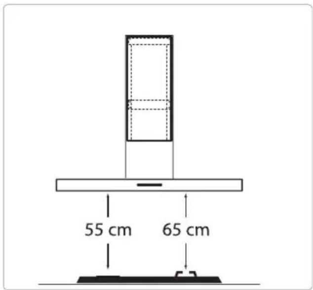
- Thedistancebetweenthelowestpointofthecookerhoodand thesupportingsurfaceforthecookingvesselsgashobshould beatleast65cm.
- If the instruction of the gashobspecify a greater distance, this hastobetaken into account.
WARNING!
Failuretoinstallscrewsorfixingdevicesinaccordancewiththese instructionsmayresultinanelectricalhazard.
If the safety instructions and warnings are not followed, the manufacturer cannot be held responsible for any resulting damage.
If you decide to discontinue using the appliance because of a fault, were recommend you cutoff the cable after removing the plug from the plug socket. Take the appliance to your municipality's waste disposalsite.
Placetheapplianceinanenvironmentthatmeetsthefollowing conditions:
- Ambianttemperaturerange: +5....+40°C;
•Humidity:30....70%RH;
•Maximumaltitude:2000metersabovesealevel.
Preparationsforinstallation
text_image
55 cm 65 cm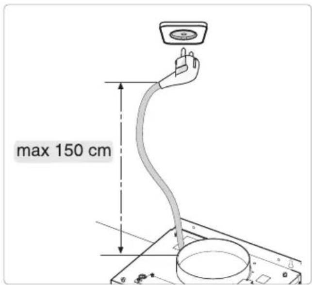
text_image
max 150 cmElectricalconnection
This appliance is manufactured in class I; it must therefore be connected to the earth system.
Makesurethesupplyvoltageratingscorrespondwiththosestatedontheappliancedataplate. Theconnectiontothemainsiscarriedoutasfollows:
•BROWN=Lphase
- BLUE=Nzero
- YELLOW/GREEN=Earth
During the electrical connection, makes sure that the electrical socket is equipped with an earth connection.
Thiscookerhoodhasbeenprovidedwithapowerplug.Wheninstallingthehood,makesurethat thisplugremainsaccessible.

WARNING!
If you want to make a fixed connection, ensure that an omnipolar switch with a contact separation of at least 3 mmis fitted in the supply line.
Appliancedimensions
Wallhoods
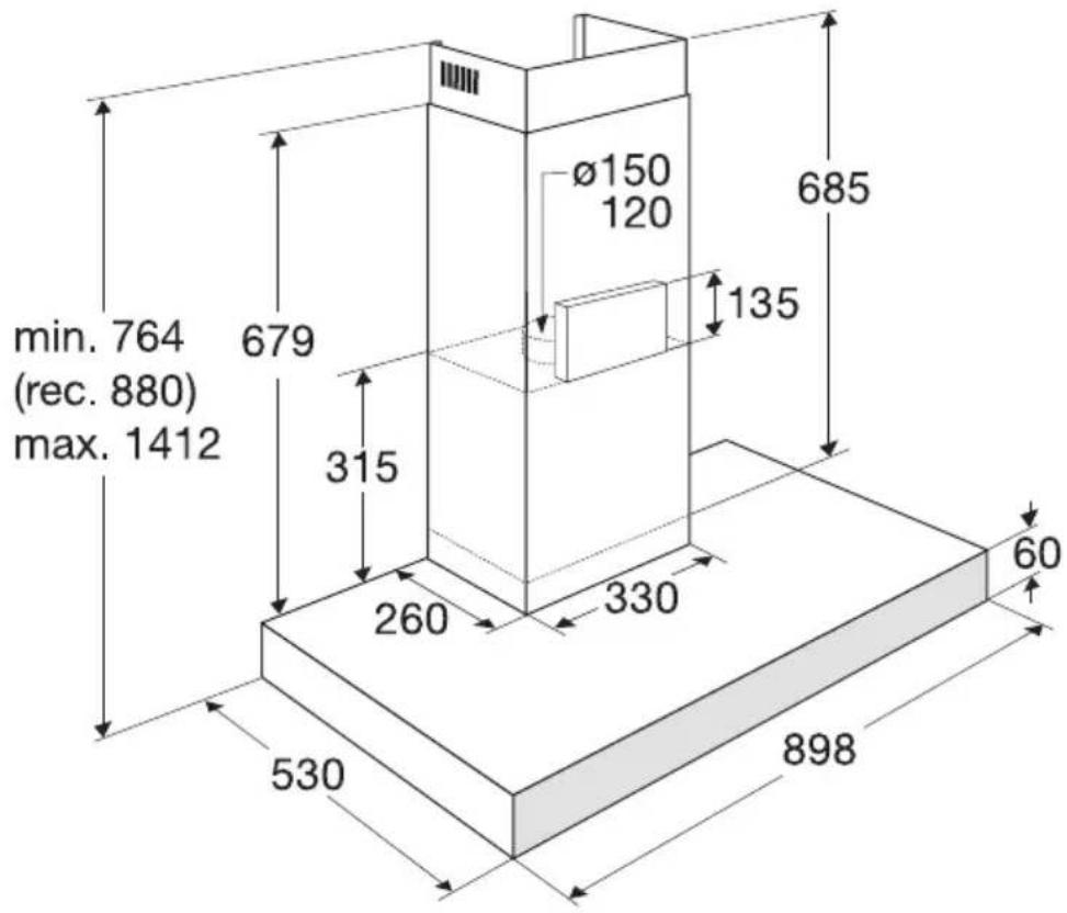
text_image
min. 764 (rec. 880) max. 1412 679 315 260 330 60 530 898 Ø150 120 135 685Islandhoods
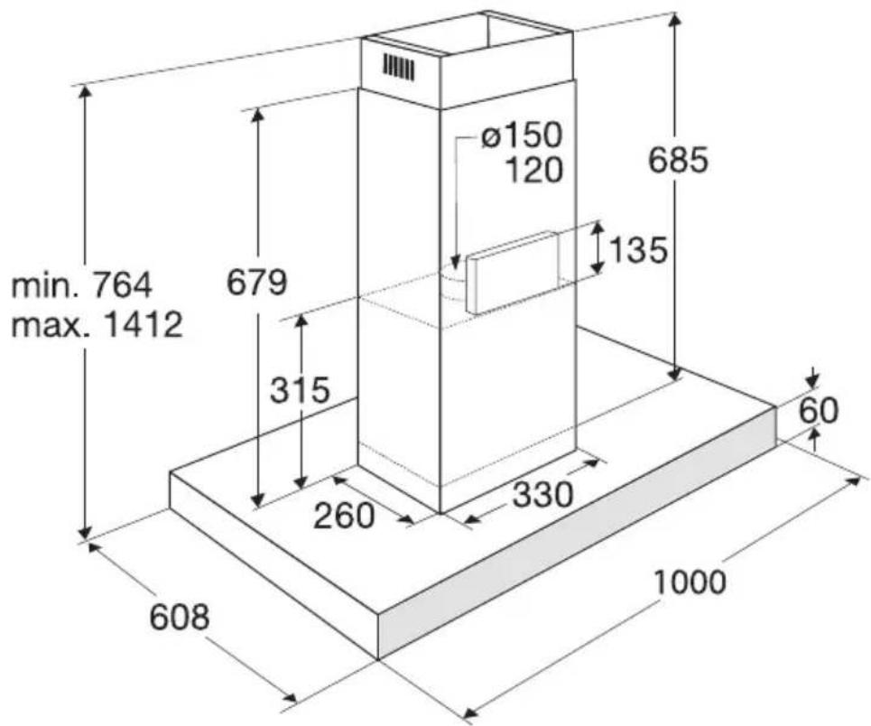
text_image
min. 764 max. 1412 679 315 260 330 608 1000 Ø150 120 685 135 60Built-in
Wallhoods
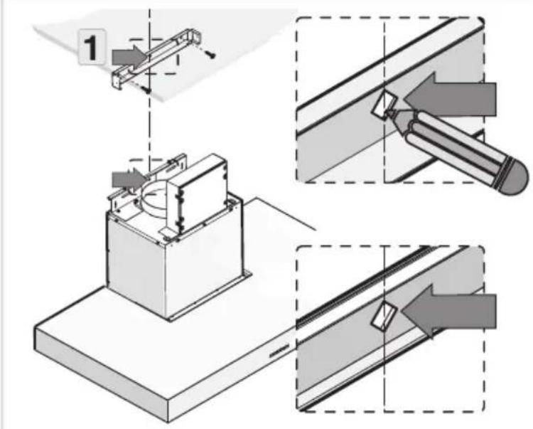
1
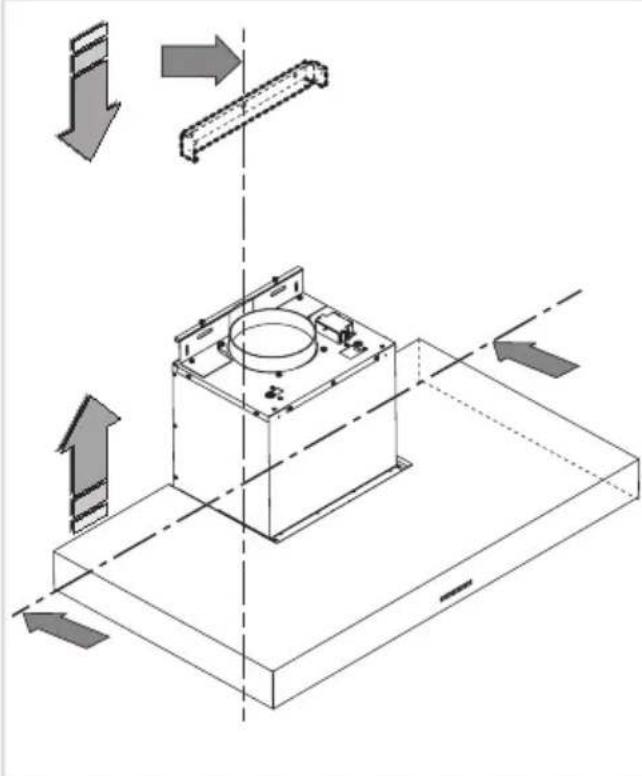
natural_image
Isometric technical diagram of a mechanical assembly with directional arrows indicating movement or force (no text or symbols present)2

text_image
Diagram illustrating a 3D mechanical assembly with tool, arrows indicating movement, and two inset images showing cylindrical components.3
text_image
Technical diagram illustrating a mechanical assembly with labeled components and directional arrows indicating process steps.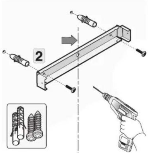
text_image
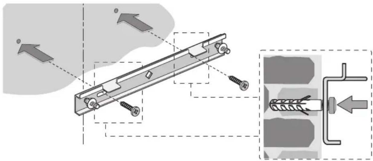
Diagram illustrating a mechanical assembly with labeled parts and a close-up of screw thread arrangement using a tool.4
text_image
Technical diagram showing mechanical assembly with screws and a pipe connection, annotated with directional arrows and shaded regions.5
text_image
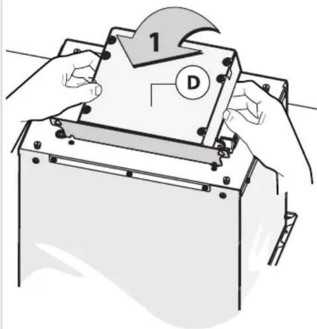
1 D6
text_image
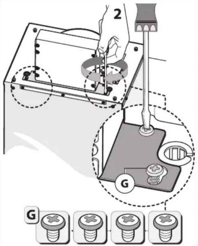
2 G G7
text_image
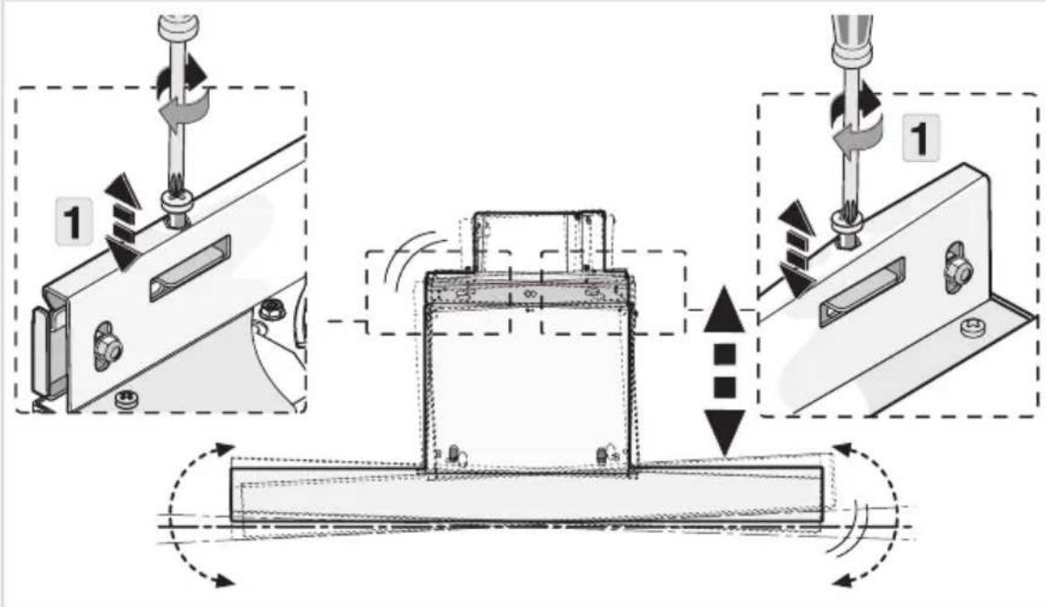
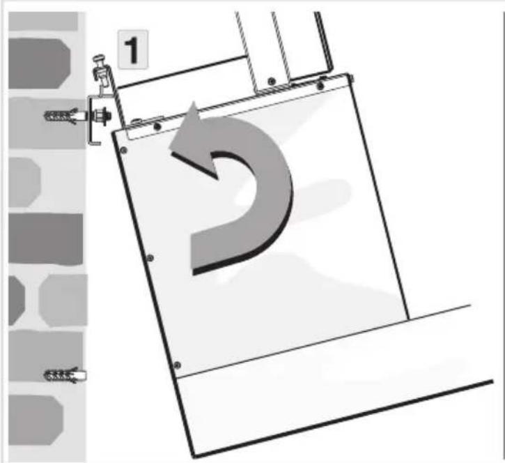
1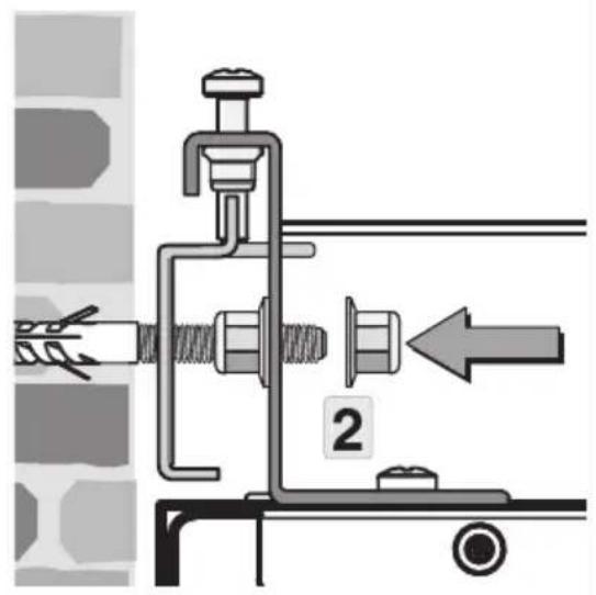
text_image
Technical diagram showing mechanical assembly with labeled component '2' and directional arrow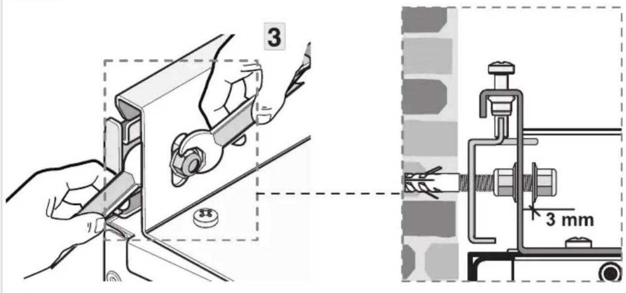
text_image
3 3 mm8
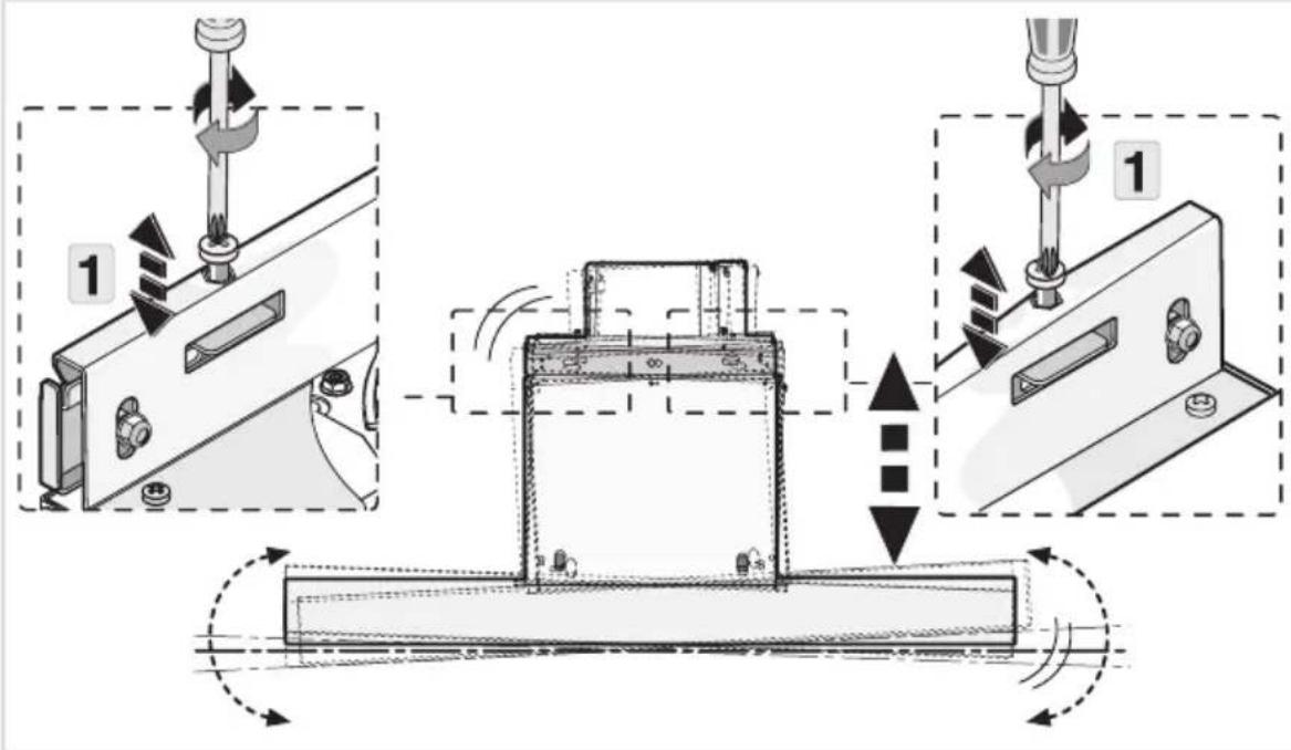
text_image
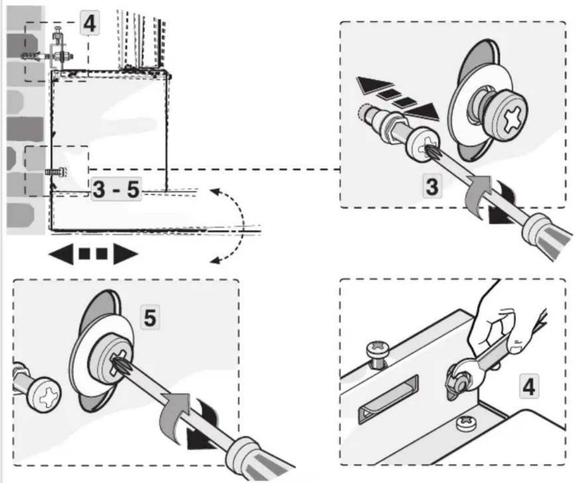
Technical diagram illustrating a mechanical assembly process with labeled components and directional arrows indicating motion or movement.9
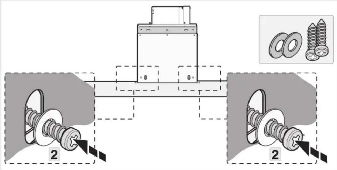
text_image
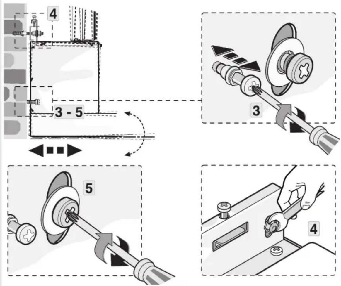
Technical diagram illustrating four different mechanical assembly steps with numbered components and directional arrows indicating motion.Installation
10
text_image
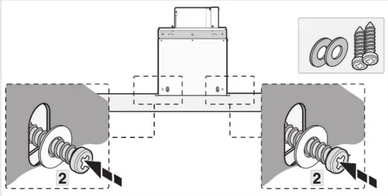
Technical diagram showing mechanical assembly with two labeled components and a close-up of screw parts, including a magnified inset image.11
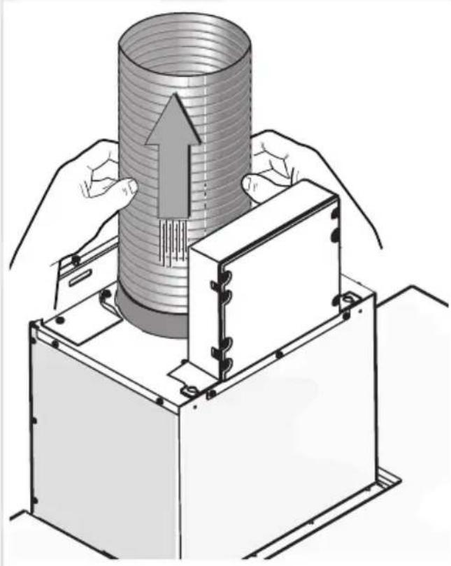
natural_image
Illustration of hands operating a cylindrical device with an upward arrow, no text or symbols present12
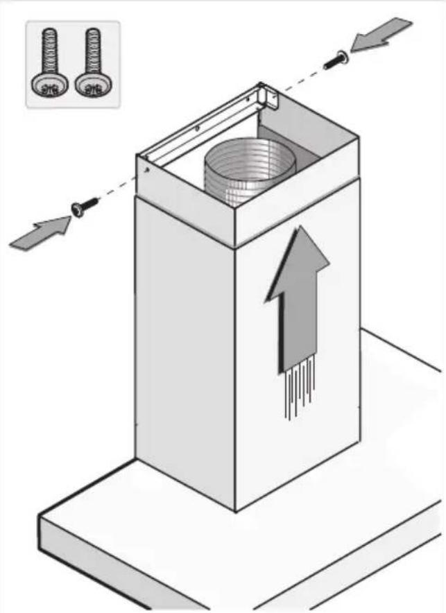
text_image
Technical diagram showing a mechanical component with arrows indicating assembly or movement, and inset images of two bolts labeled 'S16' and 'S26'.Islandhoods
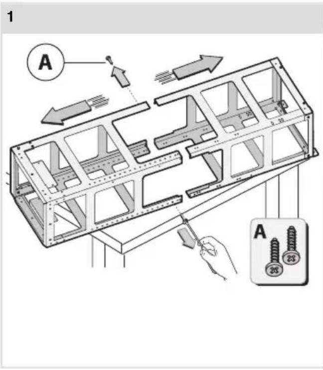
text_image
1 A A 28 23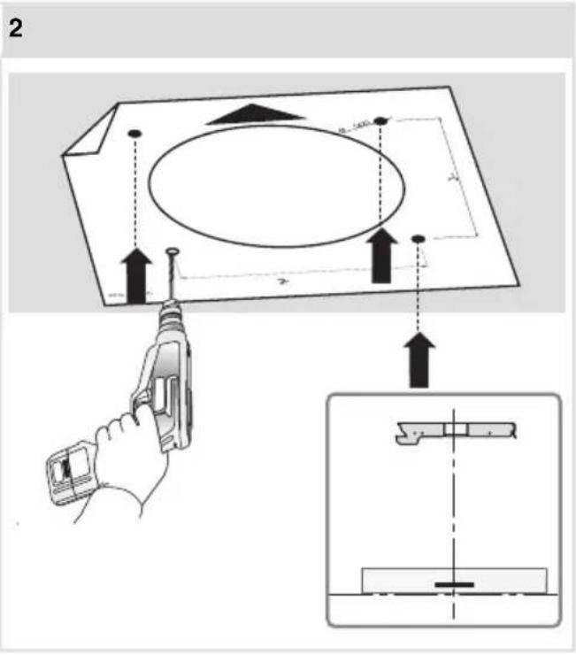
text_image
2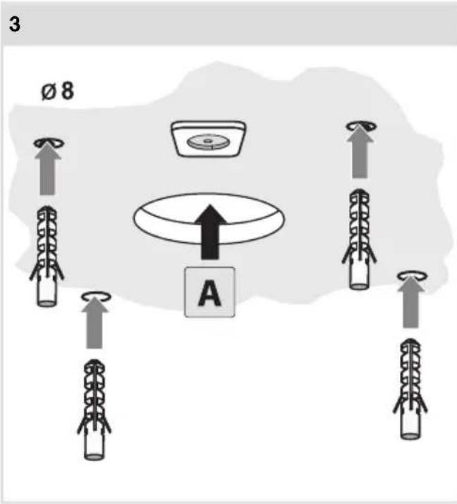
text_image
3 Ø 8 A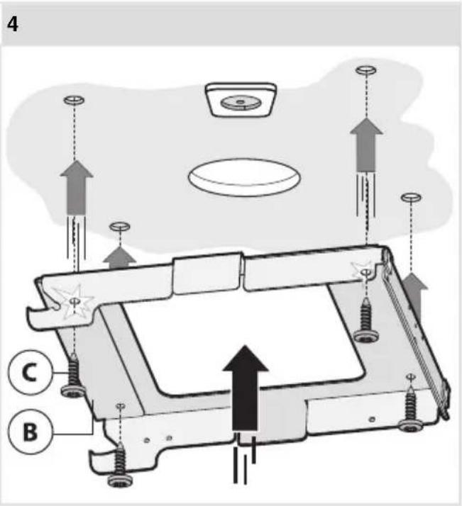
text_image
4 C BInstallation
5
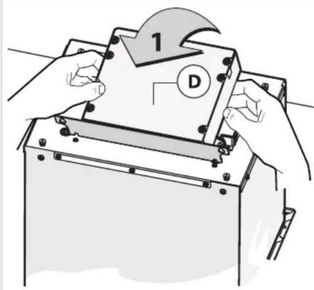
text_image
1 D6
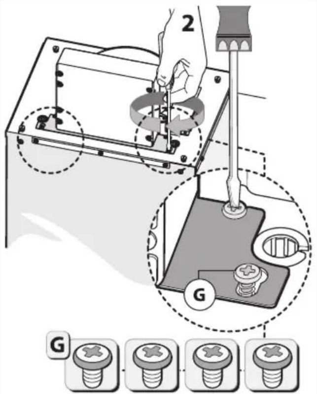
text_image
2 G G7
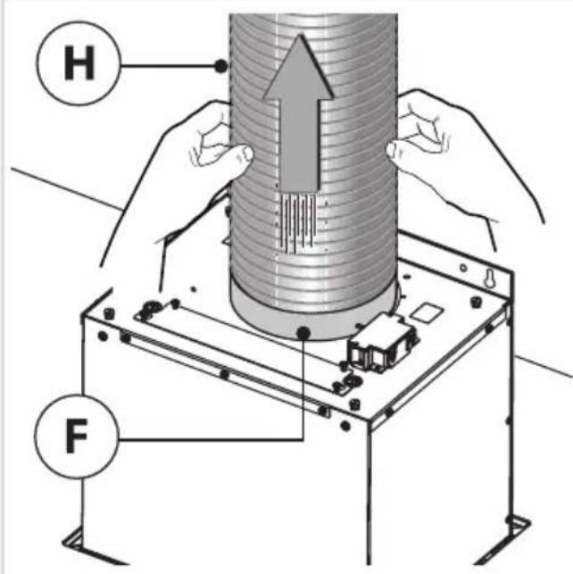
text_image
H F8
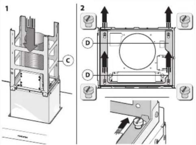
text_image
Technical diagram showing cross-sectional views of a mechanical device with labeled components and directional arrows indicating assembly or operation.9
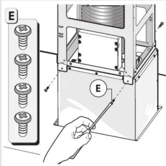
text_image
E E10
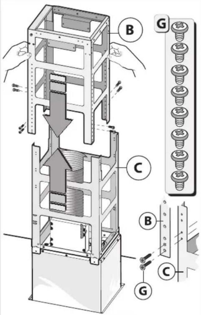
text_image
Technical diagram of a mechanical assembly with labeled parts (B, C, G) and directional arrows indicating movement or force.11
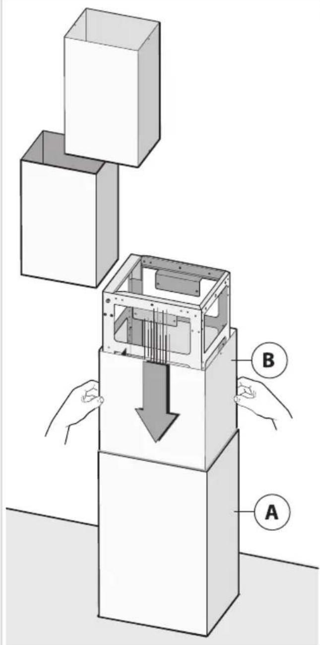
text_image
Diagram illustrating a mechanical assembly with labeled components A and B, showing a downward force on the internal structure.12
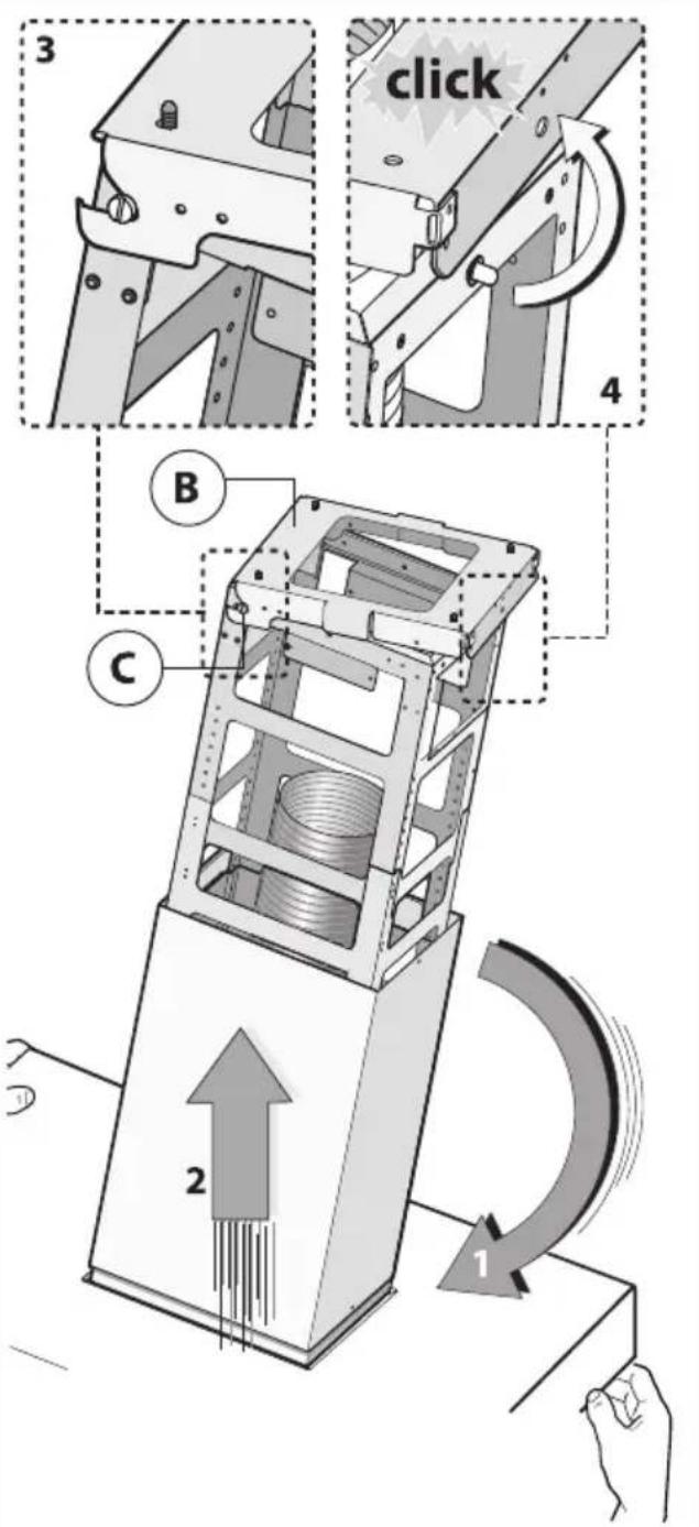
text_image
3 click 4 B C 2 113
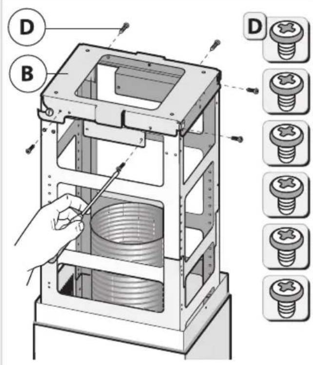
text_image
Technical diagram of a mechanical device with labeled parts (D, B) and corresponding screw assembly diagrams.14
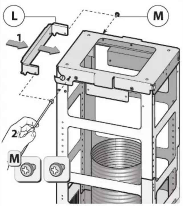
text_image
L 1 M 2 M15
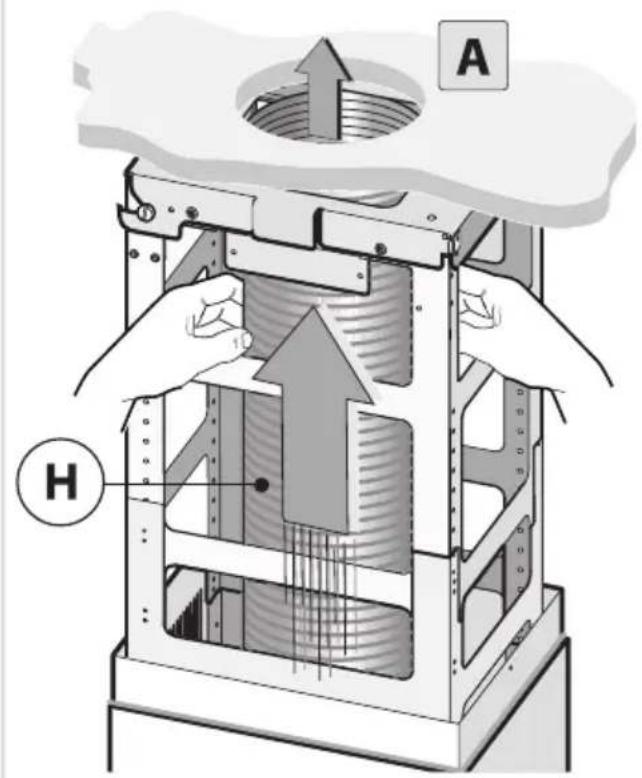
text_image
A H16
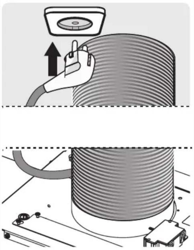
natural_image
Illustration of a hand using a cable to lift a cylindrical component, with no visible text or symbols.17
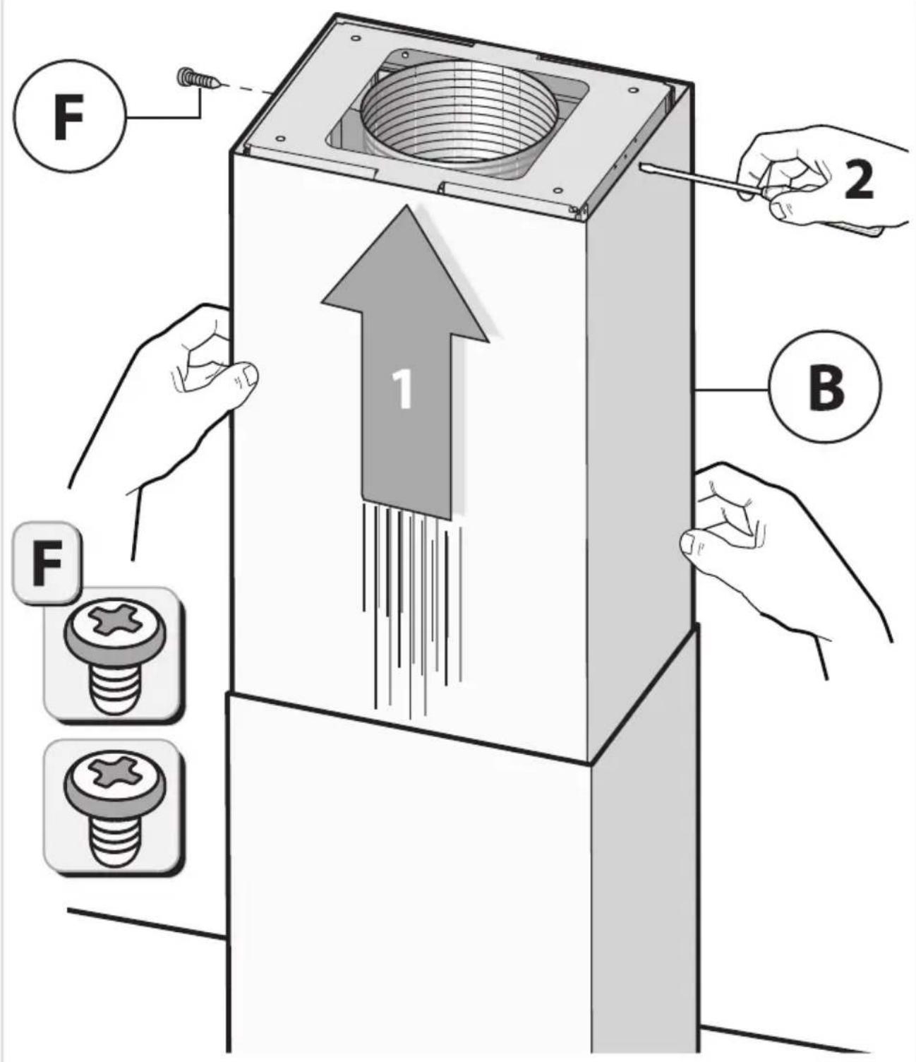
text_image
F 1 2 B F FTipsforenergy-efficient cookingwithhoods
- Usealowextractorsettingandusethehighestsetting(boost)ifnecessary.
- Awell-ventilated kitchen make esther ange hood more efficient.
- Clean filters regularly and replace filters when needed to keep the filter efficiency high, as a saturatedfiltercannotperformandleadstolongerusagetimes.
Disposal of the appliance and packaging
Sustainable material have been used during the manufacture of this appliance. This appliance must be disposed of responsibly at the end of its service life. Ask your local authorities for more information about how to do this.
The appliance packaging is recyclable. The following may have been used:
- cardboard;
•polyethylenefilm(PE);
•CFC-freepolystyrene(PSrigidfoam).
Disposeofthesematerialsinaresponsiblemannerandinaccordancewithgovernmentregulations.
text_image
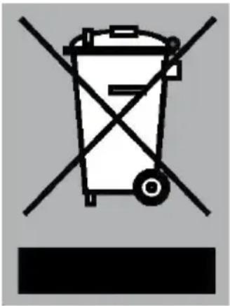
Warning symbol for a trash bin with crossed lines indicating no waste or discharge, and a black rectangle below.Theproducthasbeenmarkedwithacrossed-outdustbinsymbolto remindyouoftheobligationtodisposeofelectricalhousehold appliancesseparately. Thismeansthattheappliancemaynotbe includedwithnormaldomesticrefuseattheendofitsservicelife. Theappliancemustbetakentoaspecialmunicipalcentreforseparated wastecollectionortoadealerprovidingthisservice.
Aseparate collection of household appliances help to prevent any potential negative impact on the environment and human health caused by improper disposal. It ensures that them also of which the appliance is composed can be recovered to obtain significant savings in energy and raw materials.
CE
Declarationofconformity
WeherebydeclarethatourproductssatisfytheapplicableEuropean directives, ordersandregulations, aswellastherequirementsstated inthereferencedstandards.
Yournotes
Yournotes
ATAG
www.atag.nl
www.atag.be