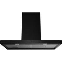
WS90292MX - Basket Atag - Free user manual and instructions
Find the device manual for free WS90292MX Atag in PDF.


User questions about WS90292MX Atag
0 question about this device. Answer the ones you know or ask your own.
Ask a new question about this device
Download the instructions for your Basket in PDF format for free! Find your manual WS90292MX - Atag and take your electronic device back in hand. On this page are published all the documents necessary for the use of your device. WS90292MX by Atag.
USER MANUAL WS90292MX Atag
natural_image
Line drawing of a kitchen chimney with ventilation ducts (no text or symbols)GEBRUIKSAANWIJZING
Afzuigkap
NL
WS90211MX
WS90292MX
WS90212MX
natural_image
Simple circular graphic with a white semicircle on a dark background, resembling a partial clock face or gauge (no text or symbols)- Raakkortdeverlichtingstoetsaan.
natural_image
Simple graphic with a grid icon and a pie chart on a black background (no text or symbols)natural_image
Simple circular graphic with a white half-circle and radiating lines on a dark background (no text or symbols)natural_image
Two black rectangular blocks with white circular and square icons, no text or symbols present.natural_image
Illustration of a person gesturing toward a large screen with a small figure nearby (no text or symbols)flowchart
graph TD
    A["Top Row: Column with repeated 'Turner' icon"] --> B["Top Row: Column with repeated 'Turner' icon"]
    B --> C["Bottom Row: Column with unrolled 'Unrolled' icon"]
    C --> D["Top Row: Column with unrolled 'Unrolled' icon"]
    D --> E["Top Row: Column with unrolled 'Unrolled' icon"]
    E --> F["Top Row: Column with unrolled 'Unrolled' icon"]
flowchart
graph TD
    A["Warning"] --> B{Air Quality Inspection}
    B -->|Yes| C["Exposure to Air"]
    B -->|No| D["Exposure to Air"]
    C --> E["Exposure to Air"]
    D --> F["Exposure to Air"]
LETOP!
natural_image
Technical diagram of a mechanical assembly with directional arrows indicating movement, no text or symbols present2
text_image
Diagram illustrating a 3D mechanical assembly with tool and component placement, showing progressive assembly from pin to bolt holes.3
text_image
Technical diagram illustrating a mechanical assembly with labeled steps and directional arrows indicating process flow.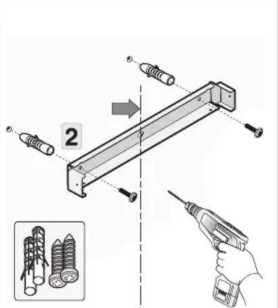
text_image
Technical diagram showing assembly steps of a mechanical component with screw and pin, including a pencil being inserted.4
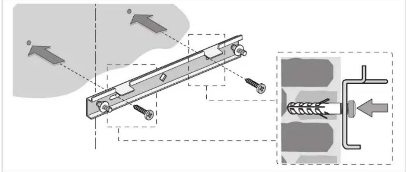
text_image
Technical diagram showing mechanical assembly with screws and a spring-loaded component, annotated with directional arrows and shaded regions.5
text_image
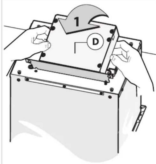
1 D6
text_image
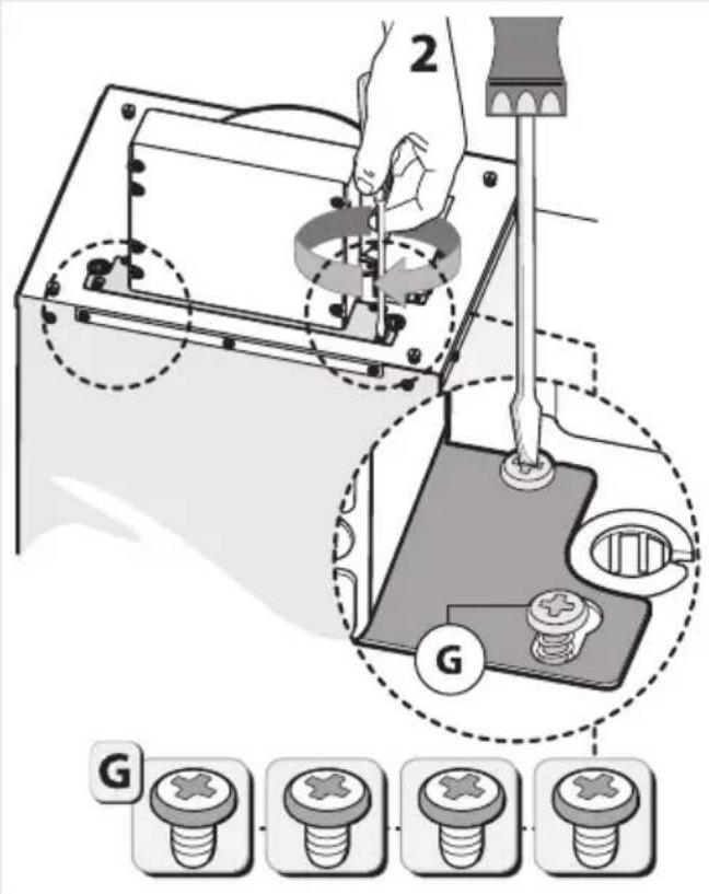
2 G G7
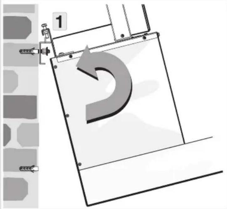
text_image
1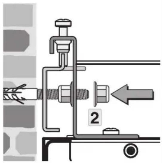
text_image
Technical diagram showing mechanical assembly with labeled parts and directional arrow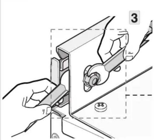
natural_image
Illustration of hands installing or adjusting a mechanical component with a numbered label (3), no text or symbols present.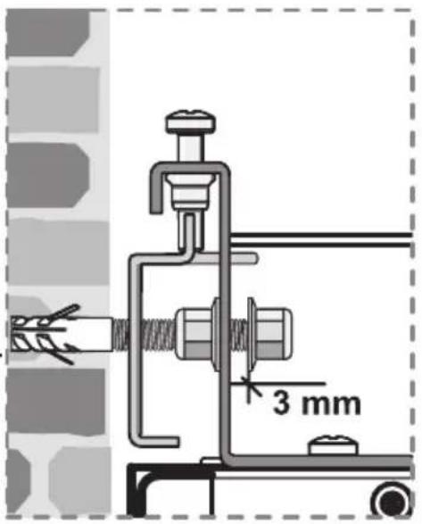
text_image
3 mm8
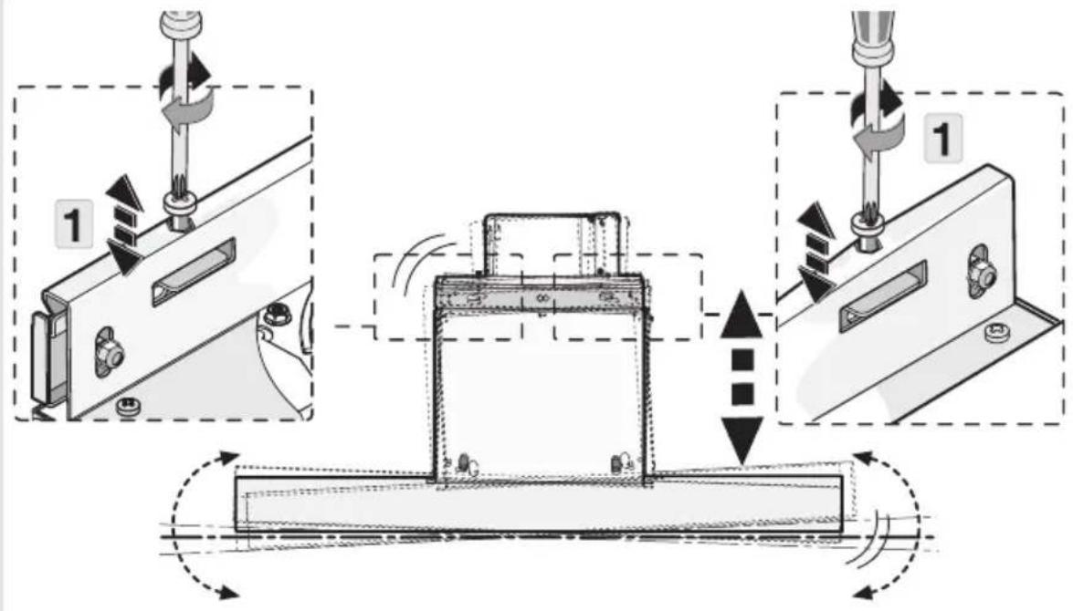
text_image
Technical diagram illustrating a mechanical assembly process with labeled components and directional arrows indicating motion or movement.9
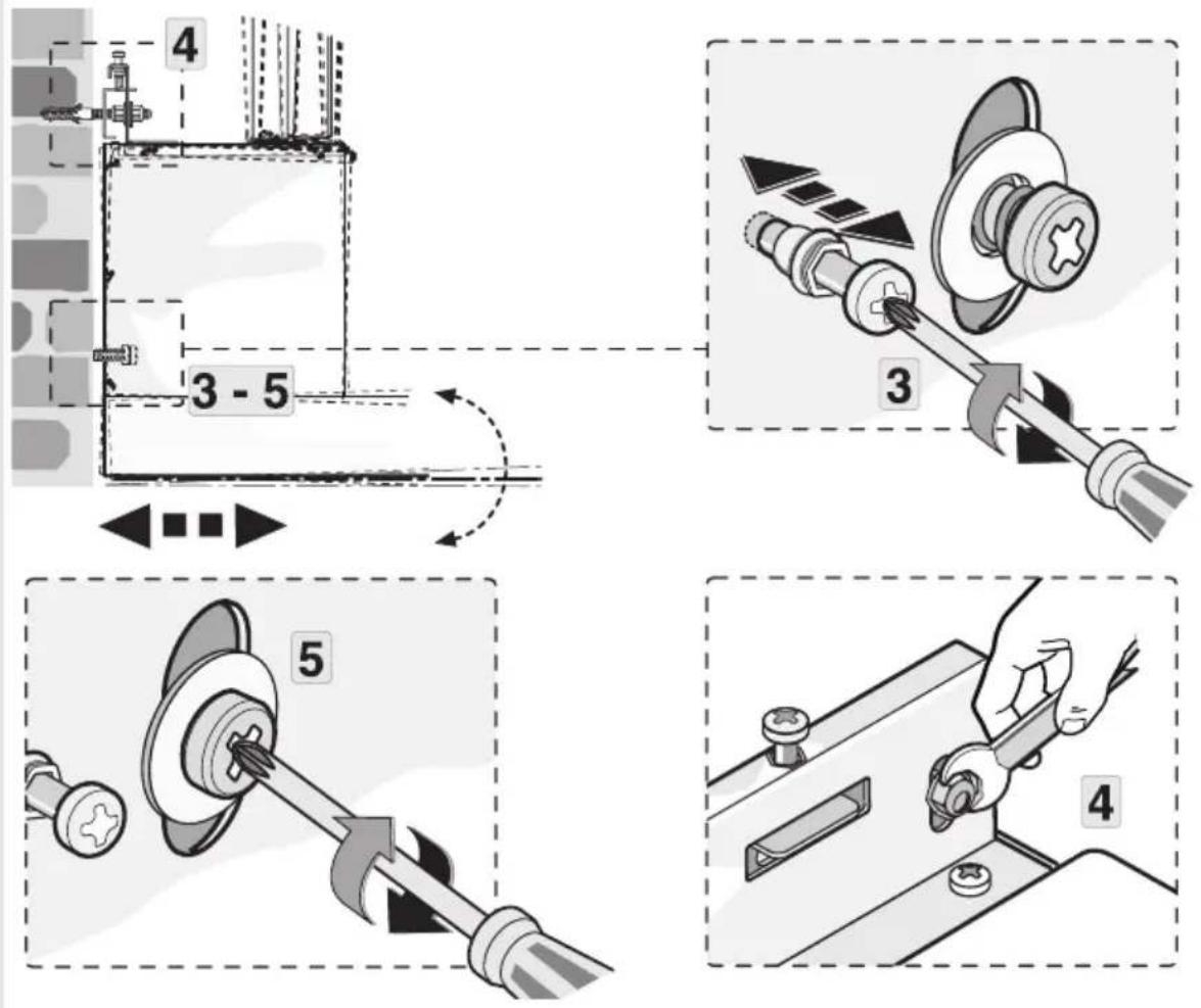
text_image
4 3 - 5 3 5 410
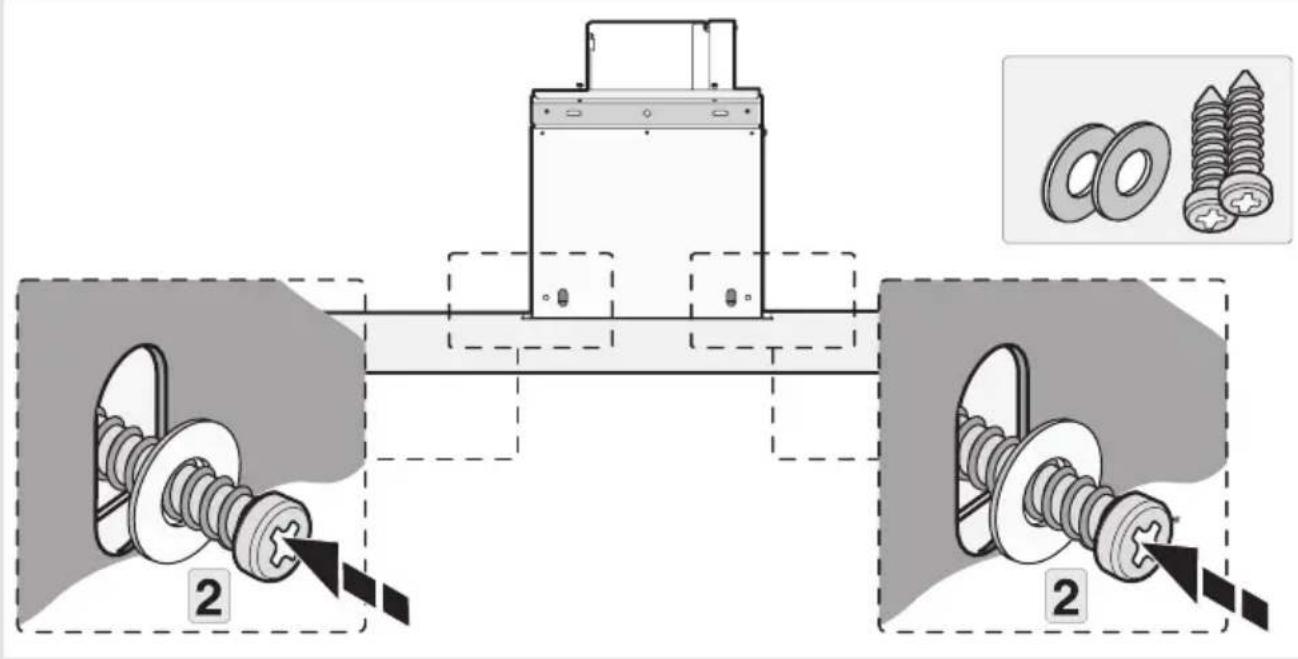
text_image
Technical diagram showing mechanical assembly with two labeled components and a close-up of bolted parts, including inset images of bolts.11
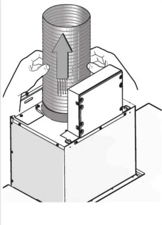
natural_image
Illustration of a mechanical assembly with hands operating a cylindrical component and a base unit, showing internal structure and motion direction (no text or symbols)12
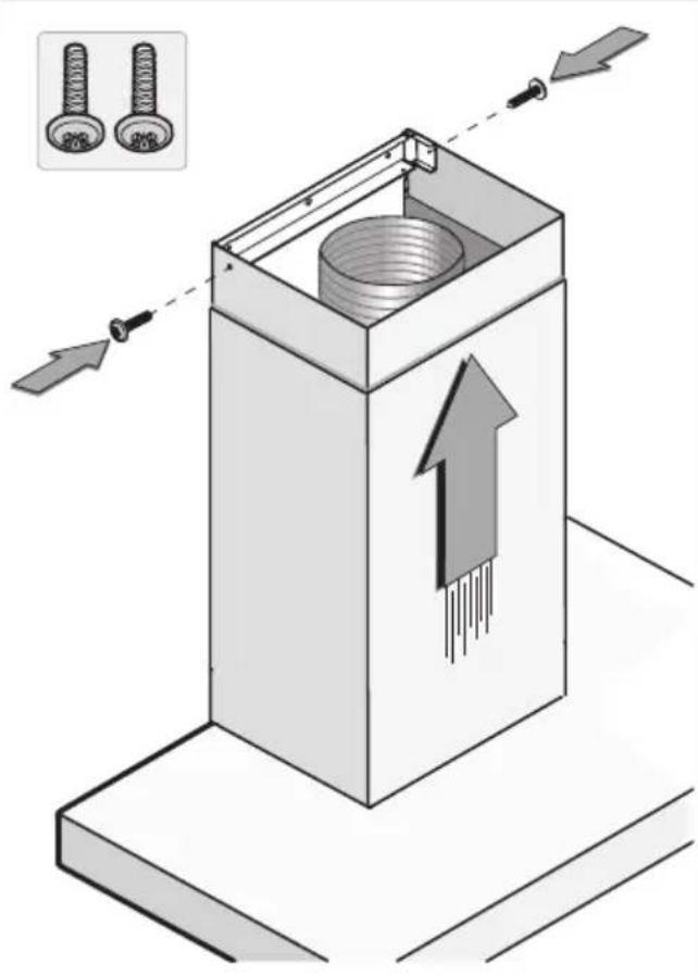
text_image
Diagram illustrating a mechanical assembly with two bolts and directional arrows indicating movement or force, showing a component inside a box.text_image
Warning symbol for a trash bin with crossed and unshaded lines indicating no waste or dischargenatural_image
Line drawing of a double boiler with front panel and top chimney (no text or symbols)NOTICED'UTILISATION
Hotteaspirante
FR
WS90211MX
WS90292MX
WS90212MX
Tablesdesmatières
natural_image
Simple white circular graphic with a half-circle and radiating lines on a black background (no text or symbols)natural_image
Simple graphic with a grid icon and a pie chart on a dark background (no text or symbols)natural_image
Simple circular graphic with a white half-circle and radiating lines on a black background (no text or symbols)natural_image
Illustration of a person gesturing toward a large screen or keyboard (no text or symbols visible)flowchart
graph TD
    A["Top Row: Column with repeated 'Turner' icon"] --> B["Bottom Row: Column with unrolled 'Turner' icon"]
    B --> C["Top Row: Column with unrolled 'Turner' icon"]
    C --> D["Bottom Row: Column with unrolled 'Turner' icon"]
    D --> E["Top Row: Column with unrolled 'Turner' icon"]
    E --> F["Bottom Row: Column with unrolled 'Turner' icon"]
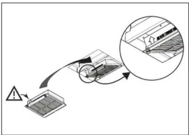
flowchart
graph TD
    A["Warning"] --> B{Air Quality Inspection}
    B -->|Yes| C["Exposure to Air"]
    B -->|No| D["Exposure to Air"]
    C --> E["Final Inspection"]
    D --> F["Final Inspection"]
REMARQUE
natural_image
Isometric technical diagram of a mechanical assembly with directional arrows indicating movement or force (no text or symbols present)2
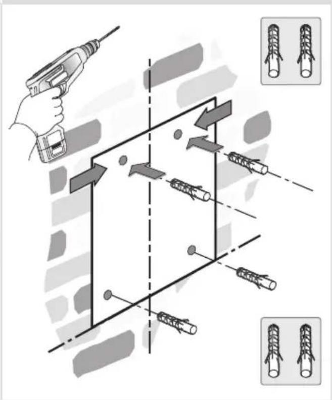
text_image
Diagram illustrating cable wire installation process with tool, wire movement, and assembly steps3
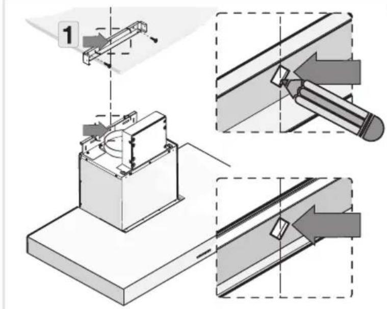
text_image
Technical diagram illustrating a mechanical assembly with labeled steps and directional arrows indicating process flow.
text_image
Technical diagram showing assembly steps of a mechanical component with numbered parts and a close-up inset of screw thread assembly.4
text_image
Technical diagram showing mechanical assembly with screws and a spring-loaded component, annotated with directional arrows and dashed lines.5
text_image
1 D6
text_image
2 G G7
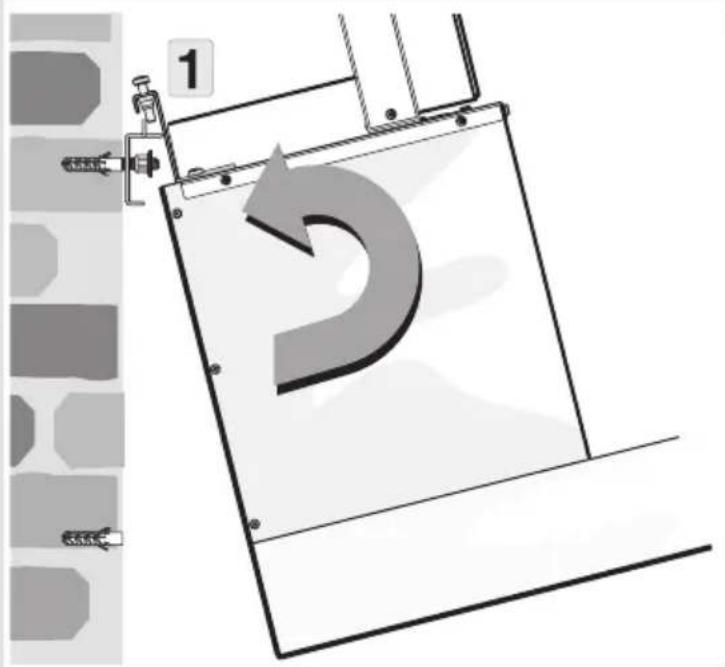
text_image
1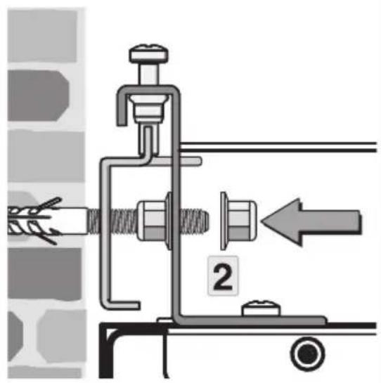
text_image
Technical diagram showing mechanical assembly with labeled parts and directional arrow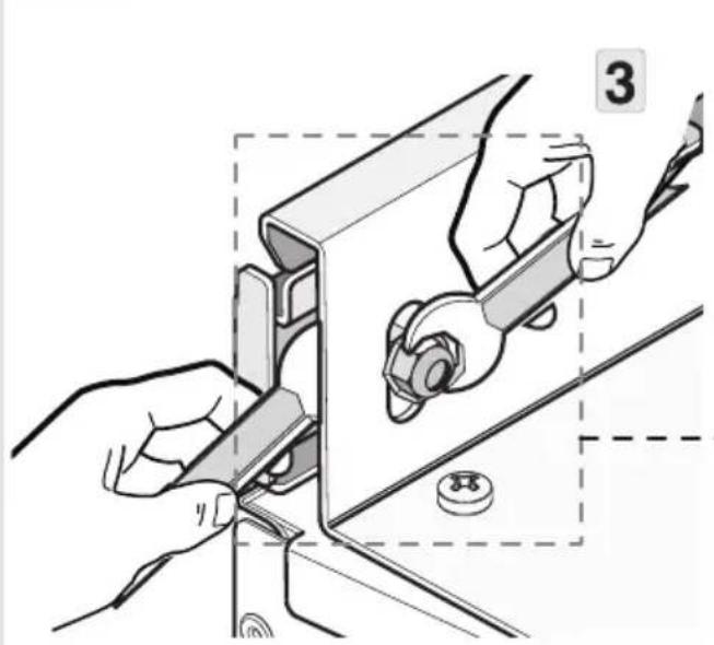
natural_image
Illustration of hands using a tool to adjust or install a mechanical component, with no visible text or symbols.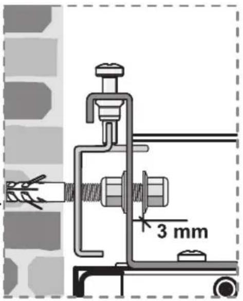
text_image
3 mm8
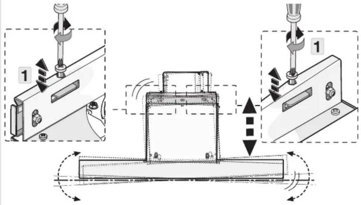
text_image
Technical diagram illustrating a mechanical assembly process with labeled steps 1 and directional arrows indicating motion or movement.9
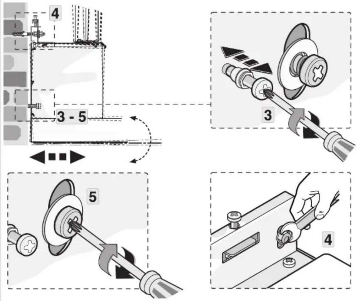
text_image
4 3 - 5 3 5 410
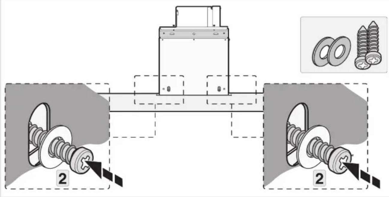
text_image
Technical diagram showing mechanical assembly with two labeled components and a close-up of bolted parts, including inset images of bolts.11
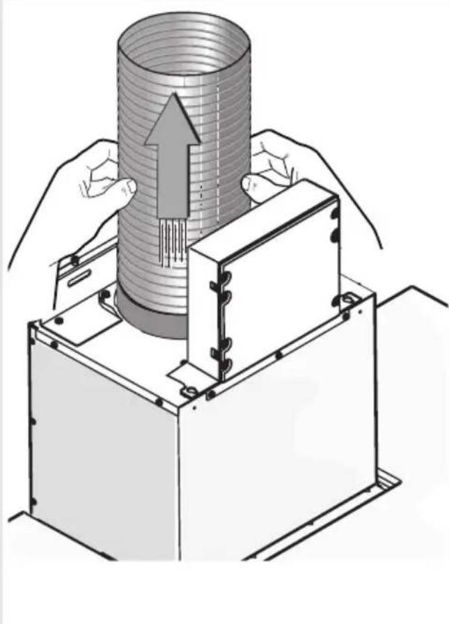
natural_image
Illustration of a mechanical assembly with hands operating a cylindrical component and a base unit, showing internal structure and motion direction (no text or symbols)12
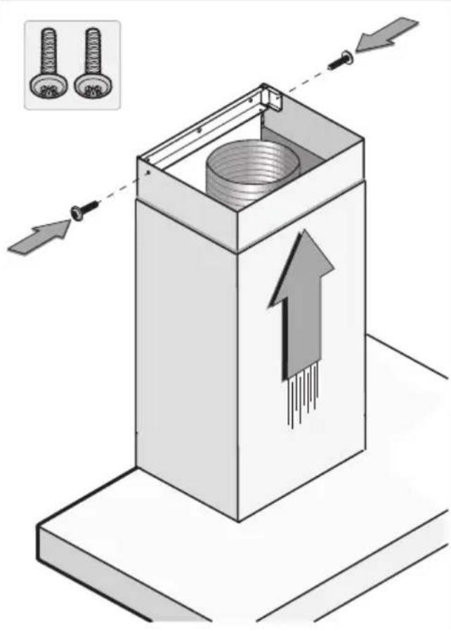
text_image
Diagram illustrating a mechanical assembly with two bolts and directional arrows indicating movement or force, showing a component inside a box.text_image
Prohibition sign for a trash bin with crossed-out lanes and a black baseline symbolnatural_image
Line drawing of a double boiler with front panel and top chimney (no text or symbols)GEBRAUCHSANWEISUNG
Abzugshaube
DE
WS90211MX
WS90292MX
WS90212MX
natural_image
Simple circular graphic with a white half-circle and radiating lines on a dark background (no text or symbols)natural_image
Simple graphic with a grid icon and a pie chart on a dark background (no text or symbols)natural_image
Simple circular graphic with a white half-circle and radiating lines on a black background (no text or symbols)natural_image
Illustration of a person interacting with a large electronic circuit board (no visible text or symbols)flowchart
graph TD
    A["Top Roof"] --> B["Recycle to Top Roof"]
    B --> C["Recycle to Bottom Roof"]
    C --> D["Recycle to Bottom Roof"]
    D --> E["Recycle to Bottom Roof"]
    E --> F["Recycle to Bottom Roof"]
    F --> G["Recycle to Bottom Roof"]
    G --> H["Recycle to Bottom Roof"]
    H --> I["Recycle to Bottom Roof"]
    I --> J["Recycle to Bottom Roof"]
    J --> K["Recycle to Bottom Roof"]
    K --> L["Recycle to Bottom Roof"]
    L --> M["Recycle to Bottom Roof"]
    M --> N["Recycle to Bottom Roof"]
    N --> O["Recycle to Bottom Roof"]
    O --> P["Recycle to Bottom Roof"]
    P --> Q["Recycle to Bottom Roof"]
    Q --> R["Recycle to Bottom Roof"]
    R --> S["Recycle to Bottom Roof"]
    S --> T["Recycle to Bottom Roof"]
    T --> U["Recycle to Bottom Roof"]
    U --> V["Recycle to Bottom Roof"]
    V --> W["Recycle to Bottom Roof"]
    W --> X["Recycle to Bottom Roof"]
    X --> Y["Recycle to Bottom Roof"]
    Y --> Z["Recycle to Bottom Roof"]
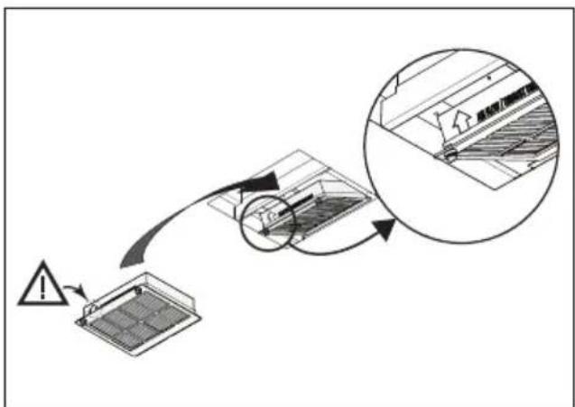
text_image
Diagram illustrating airflow or ventilation process with warning symbol and magnified detail viewHINWEIS!
natural_image
Isometric technical diagram of a mechanical assembly with directional arrows indicating movement or force (no text or symbols present)2
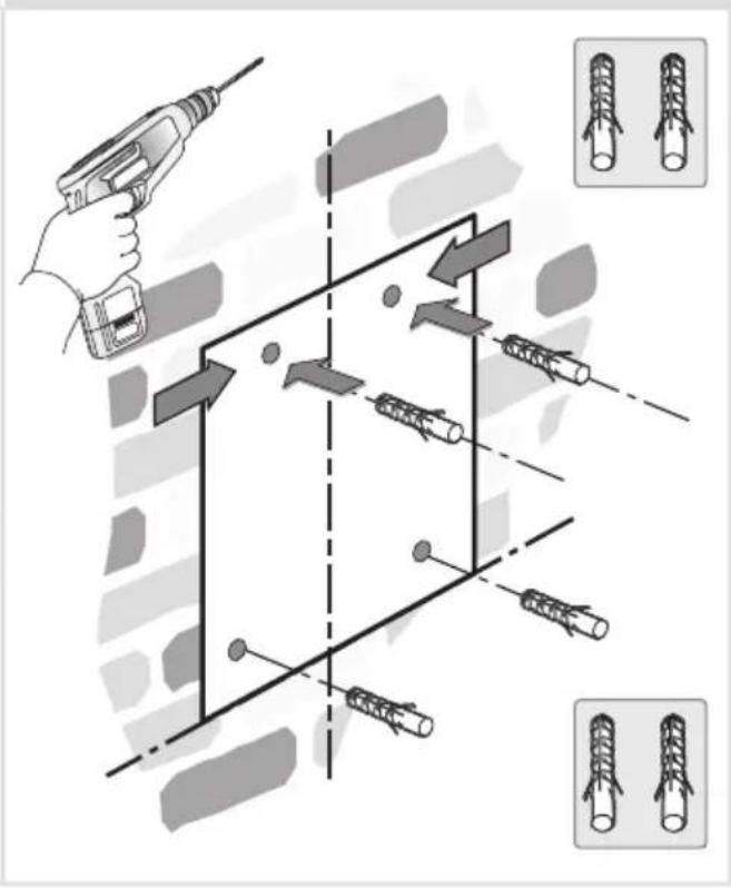
text_image
Diagram illustrating a 3D mechanical assembly with tool and component placement, showing progressive assembly from pin to bolt holes.3
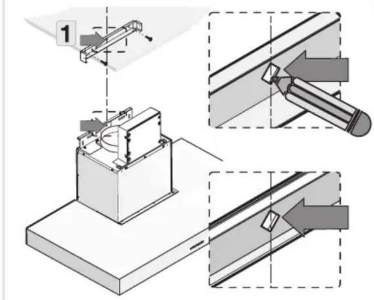
text_image
Technical diagram illustrating a mechanical assembly with labeled steps and directional arrows indicating process flow.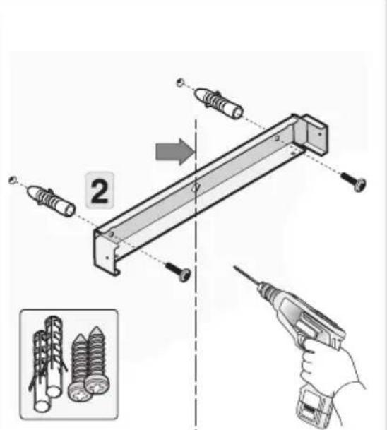
text_image
Technical diagram showing assembly steps of a mechanical component with screw and pin, including a pencil being inserted.4
text_image
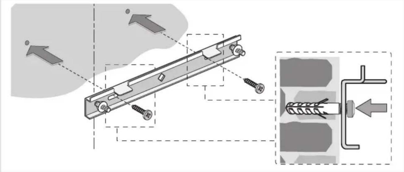
Technical diagram showing mechanical assembly with screws and a spring-loaded component, annotated with directional arrows and a magnified inset.5
text_image
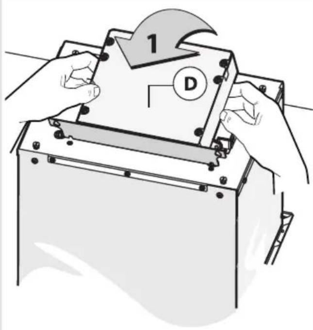
1 D6
text_image
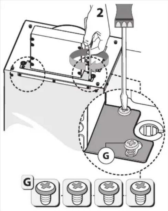
2 G G7
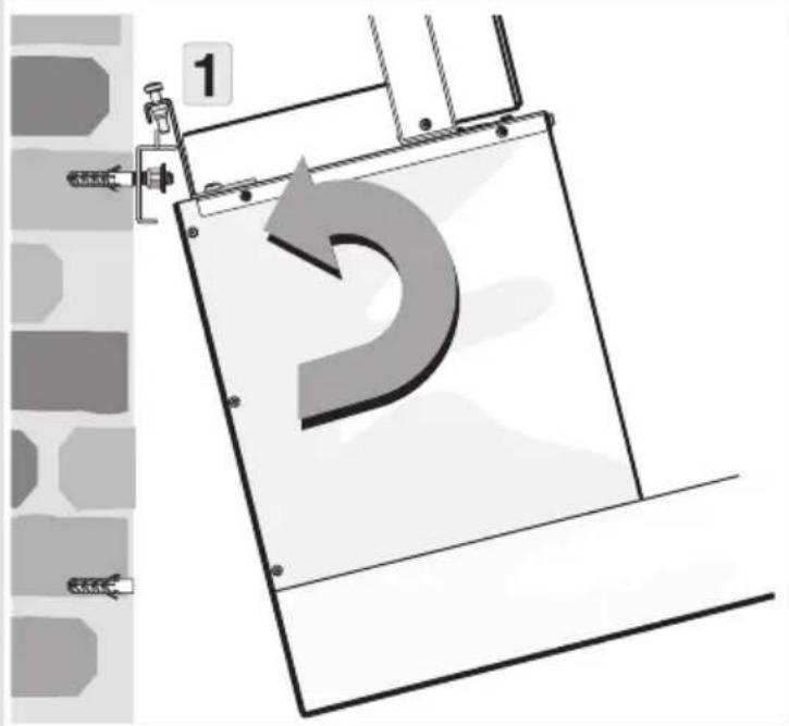
text_image
1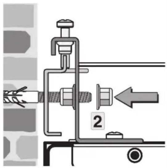
text_image
Technical diagram showing mechanical assembly with labeled parts and directional arrow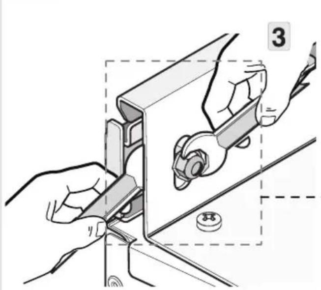
natural_image
Illustration of hands using a tool to adjust or install a mechanical component, with no visible text or symbols.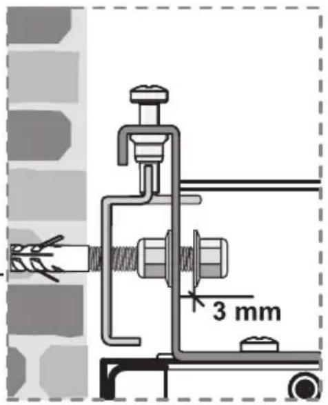
text_image
3 mm8
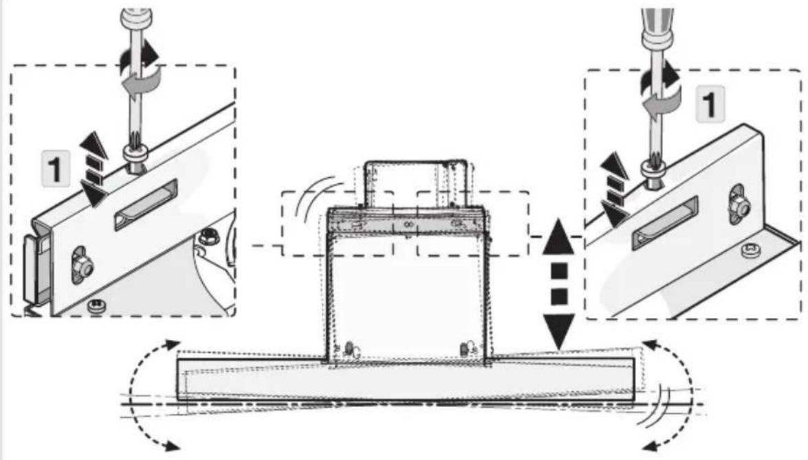
text_image
Technical diagram illustrating a mechanical assembly process with labeled steps and directional arrows indicating motion or movement.9
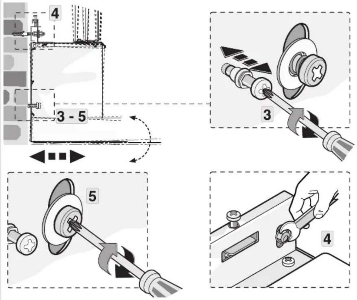
text_image
4 3 - 5 3 5 410
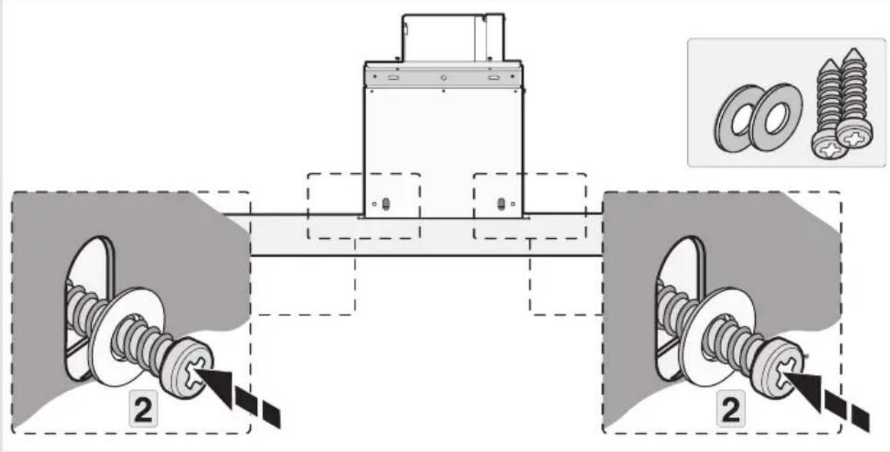
text_image
Technical diagram showing mechanical assembly with two labeled components and a close-up of bolted parts, including inset images of bolts.11
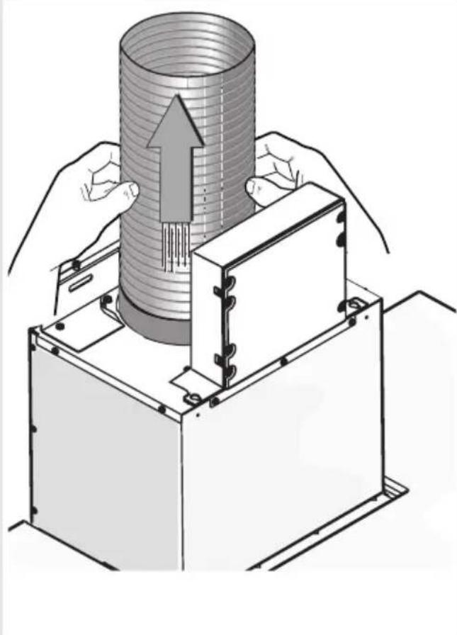
natural_image
Illustration of a mechanical assembly with hands operating a cylindrical component and a base unit, showing internal structure and motion direction (no text or symbols)12
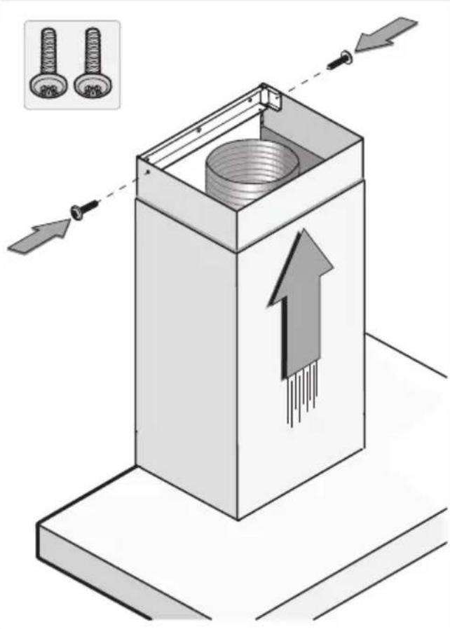
text_image
Diagram illustrating a mechanical assembly with two bolts and directional arrows indicating movement or force, showing a component inside a box.text_image
Warning symbol for a trash bin with crossed lines indicating no waste or discharge, and a black rectangle below.natural_image
Line drawing of a kitchen chimney with ventilation ducts (no text or symbols)INSTRUCTIONSFORUSE
Cookerhood
EN
WS90211MX
WS90292MX
WS90212MX
Contents
3Pictogramsused......
4Safety....
4.....Replacingtheodour/particulatematters...
7YouPtoOkeirhood....
7Dearcustomer!......
8Descriptionuserinterface......
8Cookerhoodfunctions......
9Operation....
9Switchingextractiononandoff......
9Switchontheboostsetting......
9Switchingonautomaticdelayedshut-off.....
10Switchingthelightonandoff......
10Changingthecolourtemperature......
10Recirculationuse......
10Switchingontherecirculationfunction......
10SwiTbpsfthenergiyeelfidiemfluroclkongwith....
11ClearaoAdfunction....
Making the connection between cookerhood and hob....
11
12Maintena
12Cleaning.
13
14Lighting..
15Technica
15EUProduc
15EUProduc
16Installatio
16......
18Preparatic
18Electrical
19Appliance
20Built-in....
25Environn
25
25Disposalc
26Yournote
The following symbols are used throughout the manual, and they have the following meanings:

INFORMATION!
Information, advice, tip, or recommendation

WARNING!
Warning-general danger

ELECTRICSHOCK!
Warning-dangerofelectricshock

HOTSURFACE!
Warning-dangerofhotsurface

DANGEROFFIRE!
Warning-dangeroffire
It is important that you carefully read the instructions.
WARNING!
READCAREFULLYANDKEEPITFORFUTUREREFERENCE!
Safeuse
- This appliance is only designed for household use.
- CAUTION: Accessible parts may become hot when used with cooking appliances.
- This appliance can be used by children aged from 8 years and above and persons with reduced physical, sensory or mental capabilities or lack of experience and knowledge if they have been given supervision or instruction concerning use of the appliance in asafeway and understand the hazards involved.
- Donotallowchildrentoplaywiththeappliance.
- Donotallowchildrentocleanormaintaintheapplianceunless supervised.
- Alwaysprovideadequateventilation!
- Thereshallbeadequateventilationoftheroomwhentherange hoodisusedatthesametimeasappliancesburninggasorother fuels.
- Whentherangehood and appliance supply with energy other than electricity aresimultaneously in operation, then negative pressure in the room must not exceed 4Pa (4×10 ^-5 bar).
- Localregulationsconcerningthedischargeofairhavetobe fulfilled.
- Neveruseapressurecleanerorsteamcleanertocleanthe appliance.
ELECTRICSHOCK!
Avoidtheriskofelectricshock;makesuretheapplianceis switchedoffbeforecleaningtheappliance.
- Onlyusetheapplianceinsidethehome.
- Donotusethecookerhoodifthegreasefilterhasnotbeenfitted properly!
- Donotleanagainstthecookerhood.
- Neverusethecookerhoodasaworkingsurfaceunlessthisis indicatedexplicitly.
- Grease and oil are inflammable when overheated. Remain in the cooking area when preparing meals.
- Topreventhotfatfromcatchingfire,youshouldonlydeep-fry undercontinuoussupervision.
- Thecookerhoodshouldbecleanedregularlybothontheoutside aswellastheinside(atleast1xpermonth).Insufficientcleaning oradelayinthereplacementoffilterscancauseafirehazard.
- Cleanthefiltersontime.
- Thegreasefilterscanbecomehotduringuse.Aftercookingwait atleast30minutesbeforecleaning.
- Plesenote!Intensiveusecanleadtocondensationonthe cookerhood.Condensationissimpletoremovewithadrycloth.
- Followtheinstructionsinthemanualforcleaningorreplacingthe greasefiltersand/orcarbonfilters!

DANGEROFFIRE!
Thereisariskoffireiftheinstructionsforcleaningorreplacing greasefiltersand/orcarbonfiltersarenotfollowed.
Throughgreasedepositsinthemetalgreasefilter.Neverwork withopenflameundertheappliance(eg.flambéing).Alwaysuse theappliancewiththemetalgreasefilter.Cleanthegreasefilter regularly.
Throughoverheatedfatoroil. Neverextinguishafirewithwater; alwaysuseafireblanket, lidorplate.
- The appliance may have sharpedges; please be careful during cleaning.
Safety
- ThelightemittedbyLEDlightsisverydazzlingandcandamage theeyes.DonotlookdirectlyintotheswitchedonLEDlightsfor longerthan100seconds.
- Whenwashinggreasefiltersinthedishwasheritisrecommended touseashort,non-intensiveprogramme.Checkthegreasefilter afterwashinginthedishwasherforwear(loosematerial).Wear canoccurasaresultoffrequentwashing.Ifloosematerialis visible,replacethefiltersinordertopreventthisloosematerial fromendingupinthefoodthatiscooked.
- Donotusetheapplianceintemperaturesbelow5°C.
Dearcustomer!
Pleasereadtheoperatinginstructionsbeforeuse. Theyincludegeneraltips, informationaboutthe settingsandadjustmentsyoucanmake,andthebestwaytotakecareofyourappliance.
TIP!
You can find them most recent version of the instructions for use on our website.
Enjoy your cooking!
Descriptionuserinterface
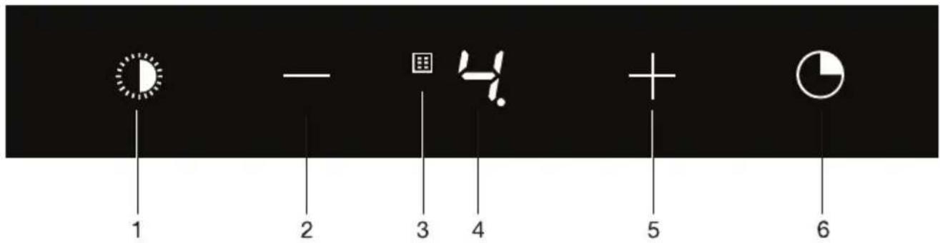
text_image
1 2 3 4 5 6- Switchingon/offanddimmingthelighting
- Reducingairextractioncapacityandswitchingoff
- Cleaning grease filters and combi-filter indicator
- Displaystatus
- Switching on and increasing air extraction capacity
6.Switchonautomaticdelayedshut-off
Cookerhoodfunctions
Recirculation
Ifitisnotpossibletodischargetheairviaanexhaustduct,youcanchoosetofiltertheextracted airandblowitbackintothekitchen;therecirculationsystem.Usingtherecirculationsystem,theair afterpassingthegreasefiltersispurifiedbyacombi-filterforodourandPM2.5andblownbackinto thekitchen.Thissystemisenergyefficientbecausenowarmairisdischarged.
If you want to set there circulation system, you must switch on there circulation function and activate the cleaning indicator combi-filter (see chapter 'Operation').
Automaticdelayedshut-off
Thetime-controlled delayed shut-off ensure that the last cooking vapours are still extracted. Thedelayed shut-off modes switches off automatically after 10 minutes.
CleanAirfunction
TheCleanAirfunctionswitchonautmaticallyfor10minutesevery24hoursatthelowestspeed setting.
Switchingextractiononandoff
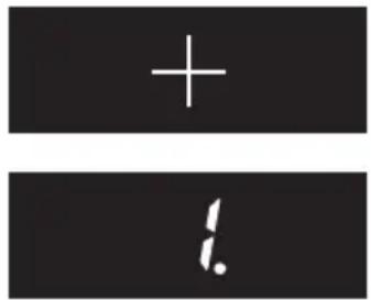
text_image
+ . !- Touchthe+(plus)key.
- Thecookerhoodwillswitchonatthelowestsetting.
- Touchthe+(plus)keyforahigherfansetting.Touchthe+(plus)keyfor2secondstoselectthehighestsetting(boost)(see'Switch ontheboostsetting').
- Touchthe-(minus)keytoselectalowersetting.
- Theextractionsettingcanbereadinthedisplay.
- The extraction setting can be set between speeds level 1 to 4.
- Touchthe-(minus)keyforatleast2secondstoswitchoffthe cookerhood.
Switchontheboostsetting

natural_image
Simple black rectangle with a white plus sign in the center (no text or symbols)- Touchthe+(plus)keyforatleast2seconds.
- The boost setting (setting 'b') is switched on for 10 minutes. Thedisplaywillflashduringthisperiod. Theoriginalextraction settingwillbereactivatedafterthisperiod.

text_image
6- Shorttouchthe-(minus)keytoswitchofftheboostsetting.
NOTE!
Boostisnotavailableinrecirculationmode.
Switchingonautomaticdelayedshut-off

natural_image
Simple white circular shape on black background, resembling a pie or donut (no text or symbols)-
Touch the automatic delayed shut-off key.
-
Theautomaticdelayedshut-offindicatorwillflash.
-
Thecookerhoodwillswitchoffautomaticallyafter10minutes.
-
Switchoffautomaticdelayedshut-offbytouchingarandomkey (exceptthelightingkey).
NOTE!
If the boost setting has been selected, the automatic delayed shut-off function cannot be activated.
Switchingthelightonandoff

natural_image
Simple circular graphic with a white semicircle on a dark background, resembling a partial clock face or gauge (no text or symbols)- Shorttouchthelightingkey.
- Thelightingchangesfrommaximumtominimumstrengthand viceversa.
- Longtouchthelightingkeytosetthelightingstrength.
- Shorttouchthelightingkeytoturnoffthelight.
Changingthecolourtemperature
Youcanadjustthelightingtemperature.
- Long touch the lighting key and simultaneously the – (minus) key to make the light 'colder' or the+(plus)keytoselecta'warmer'light.
Recirculationuse
NOTE!
Ondelivery, this cooker hoodissetforexhaustairtotheoutside. The hoodcanalsobesetto recirculationuse (the airisblownbackintotheroomafterfiltrationthroughgreasefiltersanda combi-filter).
With are circulation modification the air will first be cleaned by the grease filters and then odours and particulatematters (PM2.5) will be filtered by the combi-filter. The cleaned air is recirculated back into the kitchen.
Switchingontherecirculationfunction

natural_image
Simple graphic with a grid icon and a pie chart on a black background (no text or symbols)- Continuouslytouchthetimerkeyandthelightingkeysimultaneously untilthefilterindicatorflashes3times.
- Thecookerhoodissetforrecirculationuse.

natural_image
Simple circular graphic with a white half-circle and radiating lines on a dark background (no text or symbols)Switchofftherecirculationfunction
- Simultaneously shorttouch the timer key and the lighting key until the filter indicator stay on.
CleanAirfunction
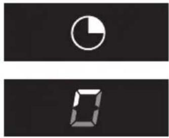
natural_image
Two abstract digital display icons, one with a white circle and the other with a black square grid (no text or symbols)TheCleanAirfunctionallowsyoutofreshentheairinyourkitchenforamaximumof24hoursatlevel1.
1.Switchoffthecookerhood.
- Touchthetimerkeyforapproximately3seconds.
- Thecookerhoodwillswitchonautmaticallyfor10minutes everyhouratthelowestspeedsetting.Duringextraction,the displaywillshowafast-moving'snake'.Whenthehoodswitches offafter10minutes,thedisplaywillshowaslow-moving'snake' untilthehoodswitchesonagainafter50minutes.
3.SwitchofftheCleanAirfunctioninthemeantimebytouchinga randomkey(anykeyotherthanthelightingkey).
Making the connection between cooker hood and hob
Tooperatethecookerhoodwiththehob,youmustmakeaconnectionbetweenthehobandthe hood.
Tomaketheconnection, theConnectionsetupmodeofthecookerhoodandthehobmustbe activated.
Seealsothemanualforthehob.Checkourwebsiteforthefullrangeofhobsthatcanbeconnected toyourcookerhood.
-
The hood and lights must be switched off.
-
Touchandholdsimultaneouslythe-(minus:keyandthe+(plus:keyfor3seconds.
- The lighting key, the + (plus) key, the - (minus) key and the timer key will flash simultaneously for a maximum of 3 minutes.
- On your hob, activatethepairingmodeintheusermenu(seethehobmanual)
• The connection to the hobis established.
- If the connection is successful, the cookerhood will return to standby.
NOTE!
When manually operating the hood in connection mode, the pairing will belost and must be paired again.
Cleaning
WARNING!
Important!Forallmaintenance,first,switchoffthemainspowertothecookerhoodbypulling theplugoutofthesocketorbyturningoffthehome'smasterswitch.Thehoodneedstobe cleanedregularly,bothinsideaswellasoutside(atleastasoftenasthegreasefilter).
Donotuseabrasivecleaningproducts.Donotusealcohol!
If the instructions regarding cleaning the appliance or replacing the filters are not followed, this can cause a fire. These instructions must be followed! The manufacturer is not liable for damage to the hood or fired damager resulting from incompetent maintenance or from non-adherence to the safety instruction above.
Cookerhood
Cleanthecookerhoodwithsoapywaterandasoftcloth.
Thenrinsewithcleanwater.Donotuseaggressivecleaningagentssuchascausticsoda.Thecooker hoodfinishstaysingoodconditionifitisbuffedperiodicallyfollowingtheapplicationofwax.
NOTE!
Stainlesssteelcookerhoods
Donotusescouringpadsorotherabrasivecleanersonstainlesssteelcookerhoods. Finishwith anon-abrasive, non-polishingagentandbuffthestainlesssteelinthedirectionofthegrain.
Filtercleaningindicator
The filter indicator will light after 30 operating hours.
- Thegreasefiltersshouldthenbecleaned.
- Metalgreasefiltersshouldbecleanedonceamonth(orwhenindicatedbythefiltercleaning indicator)usinganeutralcleaningagent,eitherbyhandorinthedishwasheronashort, low-temperatureprogram.
- Place the grease filters with the openings facing downwards in the dishwasher so the water can drainoutofthefilter.Aluminiumgreasefiltersbecomedullasaresultofdishwashercleaning agents.Thisisnormalanddoesnotaffecttheworking.Allowthefilterstodrainwellbefore replacing.
- Reset the memory by long touching the – (minus) key until the filter indicator goes off.
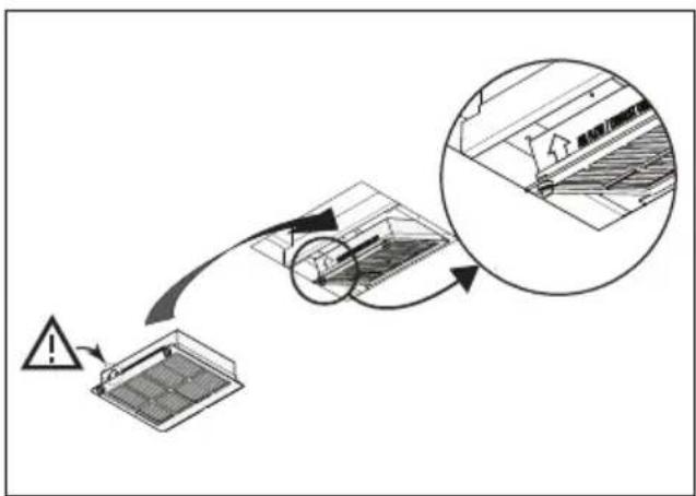
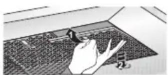
Removinggreasefilter
natural_image
Illustration of a person standing on a large grid with a hand reaching toward it (no text or symbols visible)- Switchoffthemotorandlighting.
- Openthefilter'saccesshatch.
- Removing the filter out of the hood.
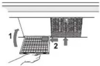
Repositionthegreasefilter
Thefiltershouldbeplacedwiththelockingmechanismonthefront.Openthefilteraccesslatch. Thenotchesatthefrontofthefilterwillthenslotin.Holdtheaccesslatchinthispositionwhenplacing thefilters.
text_image
1 2-
Slotthenotchesatthebackofthefilterinthespeciallydesigned openingofthecookerhood.
-
Tiltthefilterupwards.
-
Releasethefilteraccesshatch. Thenotchesatthebackofthefilter willextendoutwardsandslotintothespeciallydesignedopenings ofthecookerhood.
Thefilterisnowinpositionagain.
NOTE!
Replacethegreasefiltersintheiroriginalassembledposition.Positioningthegreasefilters correctlyensuresthemostefficientextraction.
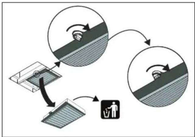
Replacingtheodour/particulatematters(PM2.5)filter
Theodour/particulatematters(PM2.5)filtermustbereplacedannually(orwhenindicatedbythe odour/fineparticlefiltercleaningindicator).
Thefilterindicatorwillflashafter360operatinghours.
- Removethescrewatthefrontsecuringthefilterholderbyturningitanti-clockwise.
- Removethefilterholderwiththefilteroutofthehood.
- Removetheoldfilteranddisposeofitwithyourresidualwaste.
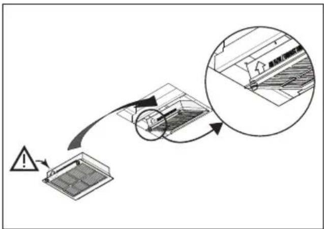
- Replace the new filter in the holder. Note: The arrow on the side indicates the airflow direction.
- Replace the filterholder by first inserting the back into thenotches.
- Re-tightenthefilterholder.
- Resetthememorybylongtouchingthe-(minus:keyuntilthefilterindicatorgoesoff.
flowchart
graph TD
    A["Top Roof"] --> B["Recycle Bin"]
    B --> C["Recycle Bin"]
    C --> D["Recycle Bin"]
    D --> E["Recycle Bin"]
    E --> F["Recycle Bin"]
    F --> G["Recycle Bin"]
    G --> H["Recycle Bin"]
    H --> I["Recycle Bin"]
    I --> J["Recycle Bin"]
    J --> K["Recycle Bin"]
    K --> L["Recycle Bin"]
    L --> M["Recycle Bin"]
    M --> N["Recycle Bin"]
    N --> O["Recycle Bin"]
    O --> P["Recycle Bin"]
    P --> Q["Recycle Bin"]
    Q --> R["Recycle Bin"]
    R --> S["Recycle Bin"]
    S --> T["Recycle Bin"]
    T --> U["Recycle Bin"]
    U --> V["Recycle Bin"]
    V --> W["Recycle Bin"]
    W --> X["Recycle Bin"]
    X --> Y["Recycle Bin"]
    Y --> Z["Recycle Bin"]
flowchart
graph TD
    A["Warning"] --> B["Component placement"]
    B --> C{Check}
    C -->|Yes| D["Exit"]
    C -->|No| E["Failure to return"]
    D --> F["End"]
Maintenance
NOTE!
- Morenoiseisproducedwhenodourfiltersareusedthanwhenthecookerhoodisusedwithanexhaustvent.
- Odourfiltersfunctionoptimallyatalowermotorspeed.Consequently,youshouldavoidtheintensivesettingasmuchaspossible.
CAUTION!
Thesaturationofthefilterdependsontheintensityofuse,themannerofcookingandtheregularity withwhichthegreasefiltersarecleaned.
Lighting

WARNING!
ThehoodisfittedwithLEDlights.Anauthorizedtechnicianmustreplacethese.Donotattempt toreplacetheLEDlightsyourself.
EUProductSheet
Datadeterminedaccordingto:
StandardEN61591andCommissionRegulations(EU)no.65/2014and(EU)no.66/2014.
| ATAGTrademark | |
| Typeofmodel | WS90211MXWS90292MXWS90212MX |
| hood)[kWh/a] | 21.7AnnualEnergyConsumption(A |
| Energyefficiencyclass | A++ |
| hood)[%] | 38.4FluidDynamicEfficiency(FDE |
| AFluidDynamicEfficiencyclass | |
| hood)[lux/W] | 72.8LightingEfficiency(LE |
| ALightingEfficiencyclass | |
| hood)[%] | 82.7GreaseFilteringEfficiency(GF |
| CGreaseFilteringEfficiencyclass | |
| ^3/h] | 333/474Airflowatminimumandma |
| ^3/h] | 760Airflowatintensiveorboostsetting |
| maximumspeedinnormaluse[dB(A)] | 47/55AirborneacousticalA-weight |
| boostsetting[dB(A)] | 67AirborneacousticalA-weighteds |
| _o) | -Powerconsumptionoffmode(P |
| _s)[W] | 0.36Powerconsumptioninstandby |
EUProductFiche
| 0.6Timeincreasefactor(f) | ||
| hood) | 33.2EnergyEfficiencyIndex(EEI | |
| BEP) [m3/h] | 315.4Measuredairflowrateatbeste | |
| BEP) | 383Measuredairpressureatbestef | |
| BEP) | 87.4Measuredelectricpowerinput | |
| L) | 2.8Nominalpowerofthelightingsys | |
| [lux] | middle) | 254.8Averageilluminationoftheligh |
Safetyregulations

WARNING!
Thisapplianceshouldonlybeconnectedbyaregisteredinstaller.
- Always follow the installation instructions in the installation manual provided.
- Checktheappliancefortransportdamage.Donotconnecta damagedappliance.
- Faultypartsmayonlybereplacedbyoriginalparts. Themanufacturercanonlyguaranteethatoriginalpartsmeet safetyrequirements.
- If the supply cord is damaged, it must be replaced by the manufacturer, its service agent or similarly qualified persons in orderto avoidahazard.
- AlwaysusetheoriginalSupplycordtoconnecttheappliance.
- Theelectrical connection must comply with national and local regulations.
- Thewallplugsocketandplugshouldalwaysbeaccessible.
- Ifastationaryapplianceisnotfittedwithasupplycordanda plug,orwithothermeansfordisconnectionfromthesupplymains havingacontactseparationinallpolesthatprovidefull disconnectionunderovervoltagecategorylllconditions,the meansfordisconnectionmustbeincorporatedinthefixedwiring inaccordancewiththewiringrules.Thisisalsoapplicablefor applianceswithasupplycordandplugwhentheplugisnot accessibleafterinstallingtheappliance.Usinganomnipolar switchwithacontactseparationofatleast3mmfittedinthefixed wiringwillfulfilthisrequirement.
- Theapplianceshouldnotbeconnectedtothemainsviaa multi-plugadapterorextensioncable,asthesafeuseofthe equipmentcannotbeguaranteed.
WARNING!
Neveropenthecasingoftheappliance.
- Disconnecttheappliancefromthemainssupplybeforestarting anyrepairwork.
- Weadviseyoutowearprotectivegloveswhenassemblingthe cookerhoodbecauseofthepossiblesharpedges.
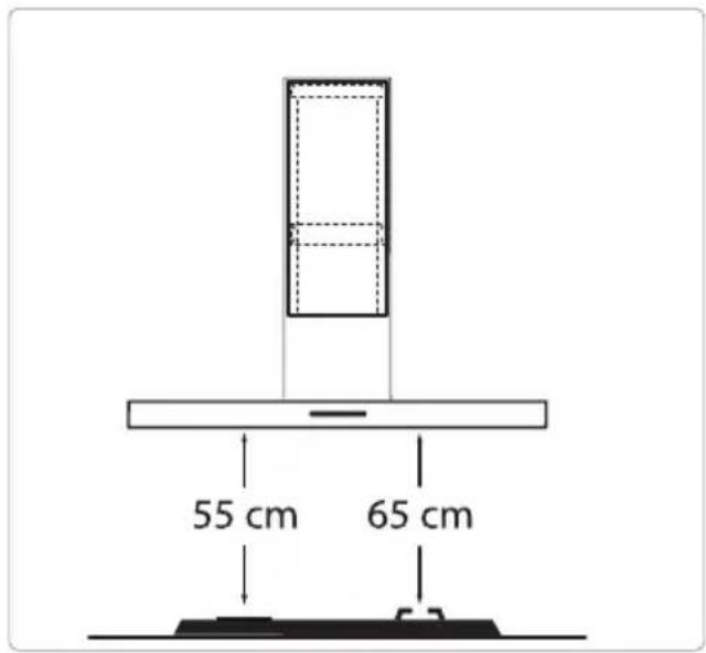
- Thedistancebetweenthelowestpointofthecookerhoodand thesupportingsurfaceforthecookingvesselsgashobshould beatleast65cm.
- If the instruction of the gashobspecify a greater distance, this hastobetaken into account.
WARNING!
Failuretoinstallscrewsorfixingdevicesinaccordancewiththese instructionsmayresultinanelectricalhazard.
If the safety instructions and warnings are not followed, the manufacturer cannot be held responsible for any resulting damage.
If you decide to discontinue using the appliance because of a fault, were recommend you cutoff the cable after removing the plug from the plug socket. Take the appliance to your municipality's waste disposalsite.
Placetheapplianceinanenvironmentthatmeetsthefollowing conditions:
- Ambianttemperaturerange: +5....+40°C;
•Humidity:30....70%RH;
•Maximumaltitude:2000metersabovesealevel.
Preparationsforinstallation
text_image
55 cm 65 cm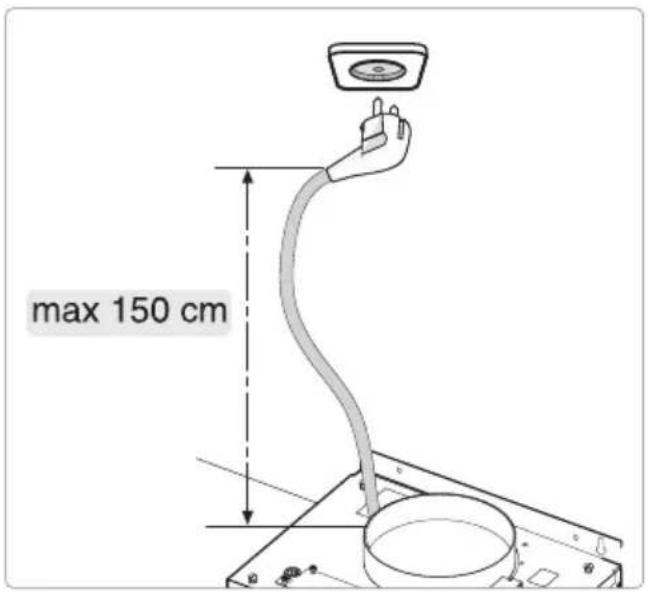
text_image
max 150 cmElectricalconnection
This appliance is manufactured in class I; it must therefore be connected to the earth system.
Makesurethesupplyvoltageratingscorrespondwiththosestatedontheappliancedataplate. Theconnectiontothemainsiscarriedoutasfollows:
•BROWN=Lphase
- BLUE=Nzero
- YELLOW/GREEN=Earth
During the electrical connection, makes sure that the electrical socket is equipped with an earth connection.
Thiscookerhoodhasbeenprovidedwithapowerplug.Wheninstallingthehood,makesurethat thisplugremainsaccessible.

WARNING!
If you want to make a fixed connection, ensure that an omnipolars switch with a contact separation of at least 3 mm is fitted in the supply line.
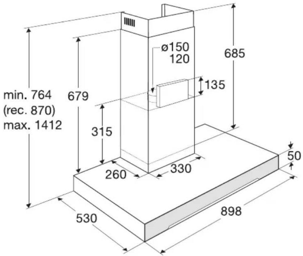
Appliancedimensions
text_image
min. 764 (rec. 870) max. 1412 679 315 260 330 530 898 Ø150 120 685 135 50Built-in Wallhoods
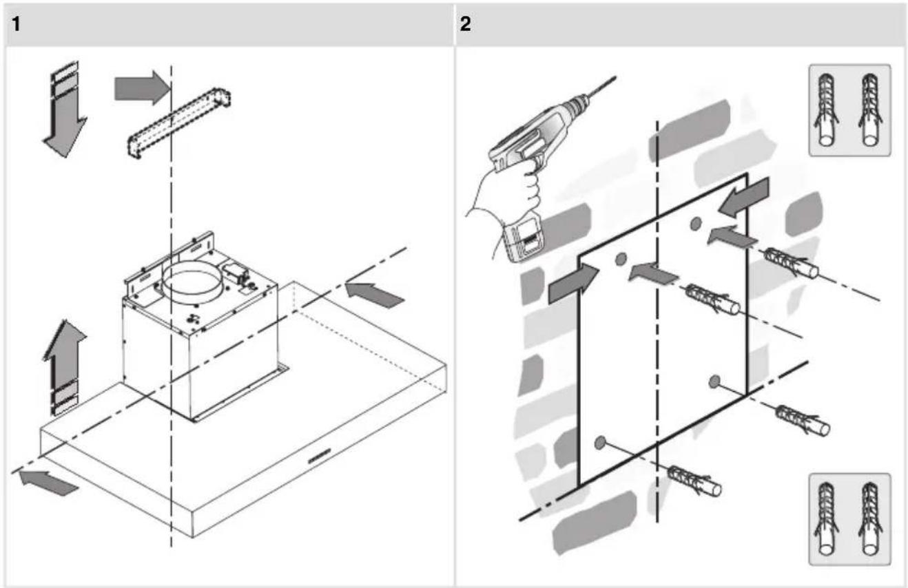
3
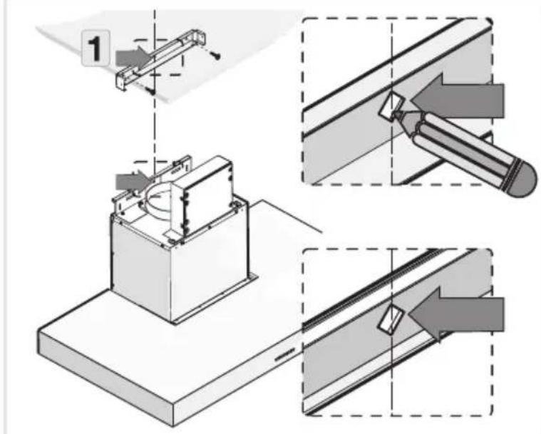
text_image
Technical diagram illustrating a mechanical assembly with labeled steps and directional arrows indicating process flow.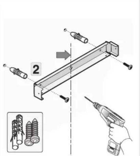
text_image
Diagram illustrating a mechanical assembly with labeled parts and a hand holding a screwdriver, accompanied by an inset image showing screw arrangements.4
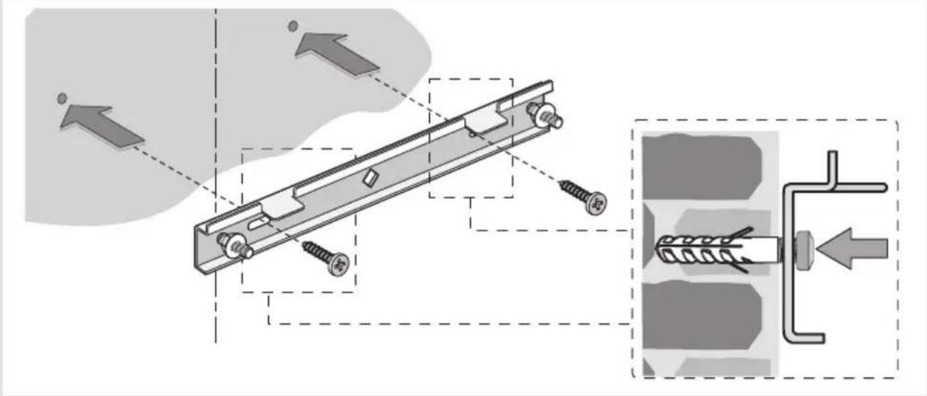
text_image
Technical diagram showing mechanical assembly with screws and a spring-loaded component, annotated with directional arrows and a magnified inset.5
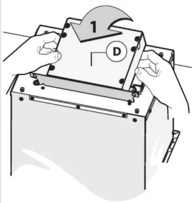
text_image
1 D6
text_image
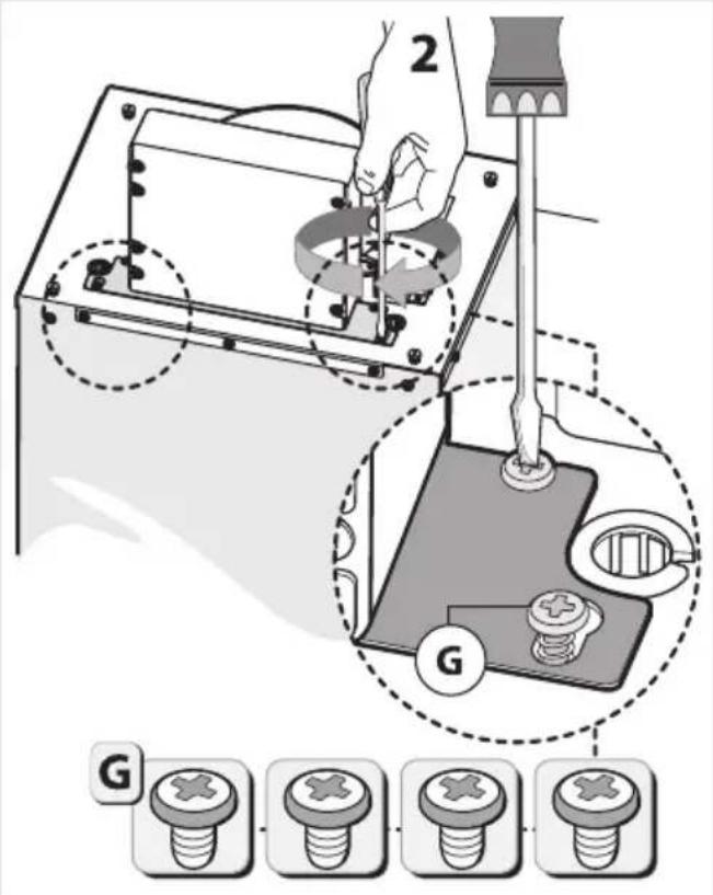
2 G G7
text_image
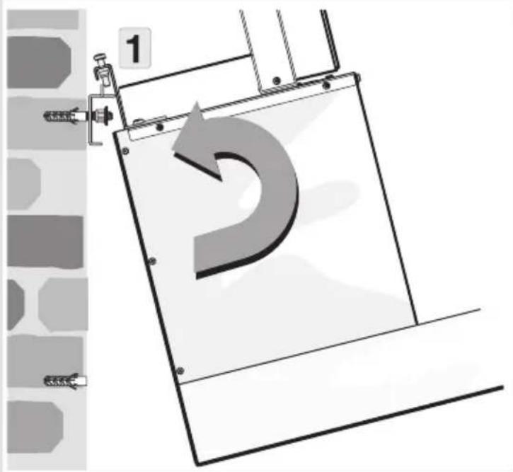
1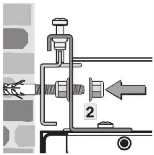
text_image
Technical diagram showing mechanical assembly with labeled parts and directional arrow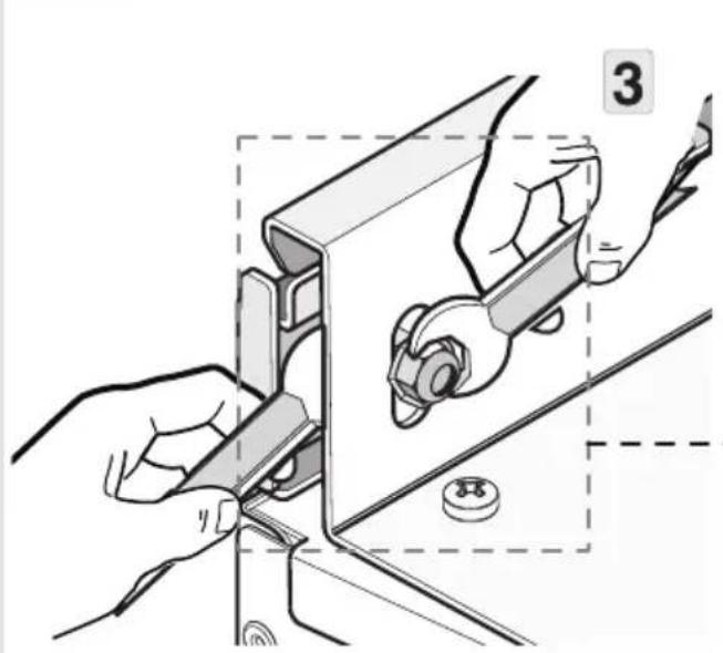
natural_image
Illustration of hands using a tool to adjust or install a mechanical component, no text or symbols present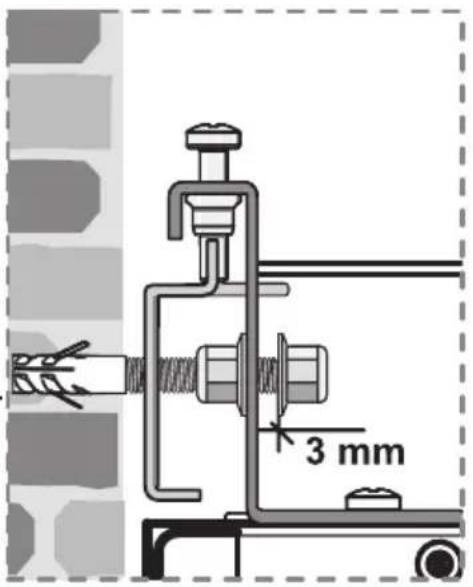
text_image
3 mm8
text_image
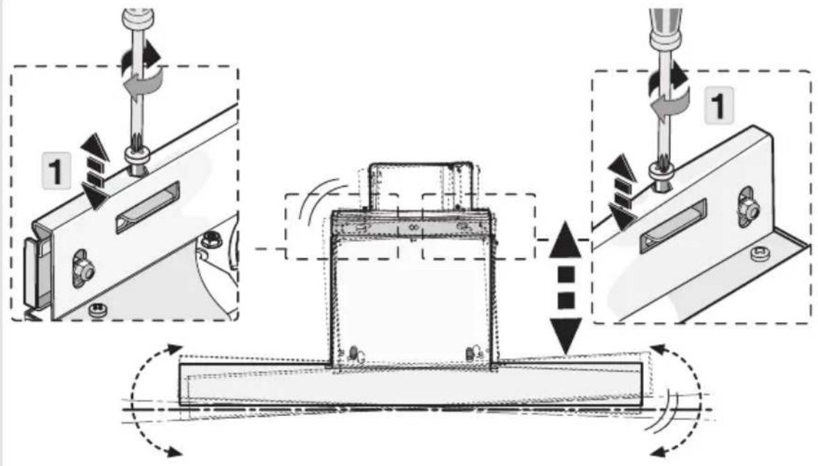
Technical diagram illustrating a mechanical assembly process with labeled steps and directional arrows indicating motion or movement.9
text_image
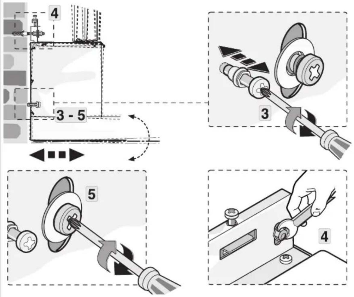
4 3 - 5 3 5 410
text_image
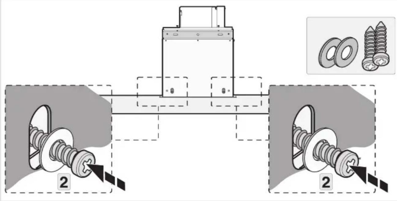
Technical diagram showing mechanical assembly with two labeled components and a close-up of bolted parts, including inset images of bolts.11
natural_image
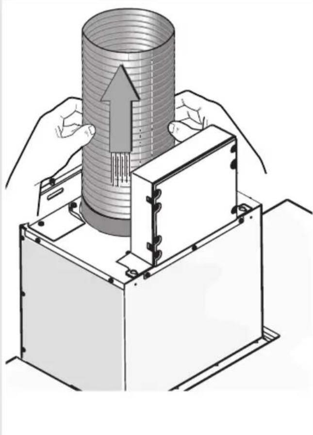
Illustration of a mechanical assembly with hands operating a cylindrical component and a base unit, showing internal structure and motion direction (no text or symbols)12
text_image
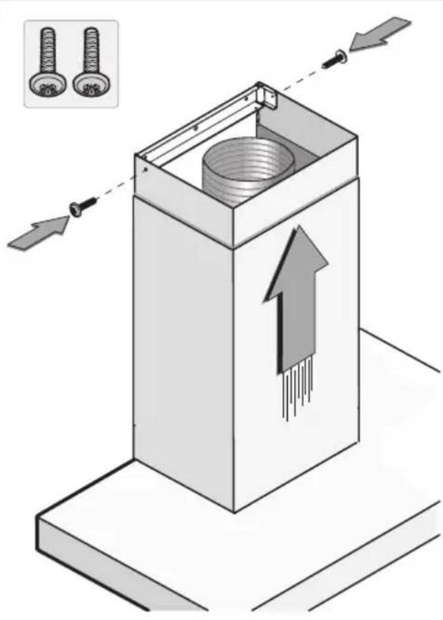
Diagram illustrating a mechanical assembly with two bolts and directional arrows indicating movement or force, showing a component inside a box.Tipsforenergy-efficient cookingwithhoods
- Usealowextractorsettingandusethehighestsetting(boost)ifnecessary.
- Awell-ventilated kitchen make estherange hood more efficient.
- Clean filters regularly and replace filters when needed to keep the filter efficiency high, as a saturatedfiltercannotperformleadstolongerusagetimes.
Disposal of the appliance and packaging
Sustainable material have been used during the manufacture of this appliance. This appliance must be disposed of responsibly at the end of its service life. Ask your local authorities for more information about how to do this.
The appliance packaging is recyclable. The following may have been used:
- cardboard;
•polyethylenefilm(PE);
•CFC-freepolystyrene(PSrigidfoam).
Disposeofthesematerialsinaresponsiblemannerandinaccordancewithgovernmentregulations.
text_image
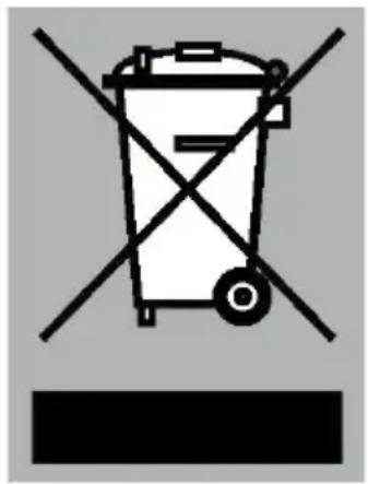
Warning symbol for a trash bin with crossed and unshaded lines indicating no waste or dischargeTheproducthasbeenmarkedwithacrossed-outdustbinsymbolto remindyouoftheobligationtodisposeofelectricalhousehold appliancesseparately. Thismeansthattheappliancemaynotbe includedwithnormaldomesticrefuseattheendofitsservicelife. Theappliancemustbetakentoaspecialmunicipalcentreforseparated wastecollectionortoadealerprovidingthisservice.
Aseparate collection of household appliances help stop prevent any potential negative impact on the environment and human health caused by improper disposal. It ensures that them material so which the appliance is composed can be recovered to obtain significant savings in energy and raw materials.
CE
Declarationofconformity
WeherebydeclarethatourproductssatisfytheapplicableEuropean directives, ordersandregulations, aswellastherequirementsstated inthereferencedstandards.
Yournotes
Yournotes
ATAG
www.atag.nl
www.atag.be