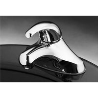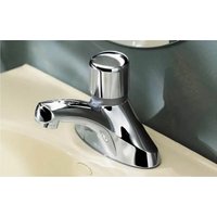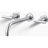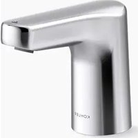
Accliv K-103A36-SBNA - Faucet KOHLER - Free user manual and instructions
Find the device manual for free Accliv K-103A36-SBNA KOHLER in PDF.


User questions about Accliv K-103A36-SBNA KOHLER
0 question about this device. Answer the ones you know or ask your own.
Ask a new question about this device
Download the instructions for your Faucet in PDF format for free! Find your manual Accliv K-103A36-SBNA - KOHLER and take your electronic device back in hand. On this page are published all the documents necessary for the use of your device. Accliv K-103A36-SBNA by KOHLER.
USER MANUAL Accliv K-103A36-SBNA KOHLER
Installation Instructions
Touchless Bathroom Sink Faucet
Record your model number:
Need help? Contact our Customer Care Center.
• USA/Canada: 1-800-4KOHLER (1-800-456-4537) Mexico: 001-800-456-4537
• Service parts: kohler.com/serviceparts
• Care and cleaning: kohler.com/clean
• Patents: kohlercompany.com/patents
Warranty
This product is covered under the KOHLER® One-Year Limited Warranty, found at kohler.com/warranty. For a hardcopy of warranty terms, contact the Customer Care Center.
Important Information

WARNING: When using electrical products, basic precautions should always be followed, including the following:

DANGER: Risk of electric shock. Connect only to a circuit protected by a Ground-Fault Circuit-Interrupter (GFCI) ^* .

WARNING: Risk of electric shock. Grounding is required. A qualified electrician should make all electrical connections.

WARNING: Risk of electric shock. Disconnect the power before servicing.

WARNING: Risk of injury or property damage. Read all instructions thoroughly before beginning installation.

CAUTION: Risk of fresh water contamination. This faucet contains back-siphonage protection. To prevent water contamination, do not remove any internal components.

CAUTION: Risk of product damage. This product contains sensitive electronic components. Do not store open containers of chemical or cleaning products near this product. Cleaning rags or sponges must be rinsed with fresh water before storage.
IMPORTANT! Do not use a switch-controlled electrical outlet (typically used for garbage disposals) to provide power to the faucet.
NOTE: This product requires a power supply that uses a specific connector to the valve box. Purchase a KOHLER AC, DC, or hybrid option. A multi-AC adapter is also available. Refer to the product specification sheet found on kohler.com for more information.
Follow all local plumbing, building, and electrical codes.
If installing the optional power supply, provide an unswitched 120 V electrical outlet within reach.
For uneven mounting surfaces (such as tile grout lines), apply a suitable sealant under the faucet. Do not use petroleum-based sealant.
*Outside North America, this may be known as a Residual Current Device (RCD).
Tools and Materials
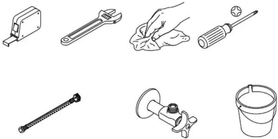
3/8" Compression X G1/2 3/8" Outlet Connection
Optional:
- Unswitched Electrical Outlet (for AC Power Supply)
text_image
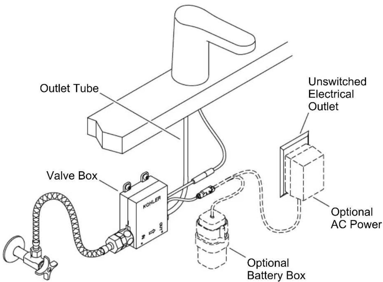
Outlet Tube Valve Box KOHLER Unswitched Electrical Outlet Optional AC Power Optional Battery Box
CAUTION: Risk of restricted water flow and product damage. The supply hose must not be taut, kinked, or twisted when installed.
NOTE: Allow adequate clearance for servicing.
☐ Before installing the faucet, verify that the area under the sink can accommodate all required components.
☐ For AC Power: Verify that there is an unswitched 120 V electrical outlet within reach.
☐ For DC Power: Determine the location of the battery box (not included) within reach of the valve box.
☐ Turn OFF the water supplies.
1. Install the Faucet
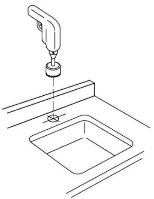
natural_image
Line drawing of a cleaning or cleaning tool applying material to a square sink (no text or symbols)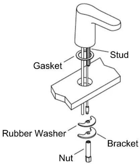
text_image
Gasket Stud Rubber Washer Nut BracketNOTE: Before drilling the mounting hole, use the following dimensions for proper placement:
Mounting Hole: 1-1/4" (32 mm) minimum to 1-1/2" (38 mm) maximum diameter.
Spout to Wall: 1-3/4" (44 mm) minimum distance between the back of the spout and the wall.
Spout to Sink: 1-1/8" (29 mm) maximum distance between the spout base and the edge of the sink bowl.
□ Determine the mounting-hole location.
Drill a hole through the mounting surface according to the surface manufacturer's instructions.
☐ Install the gasket to the bottom of the faucet.
☐ Insert the faucet through the mounting hole.
☐ From under the sink, install the rubber washer and bracket onto the stud.
☐ Thread the nut onto the stud until the faucet is secure.
2. Install the Valve Box
text_image
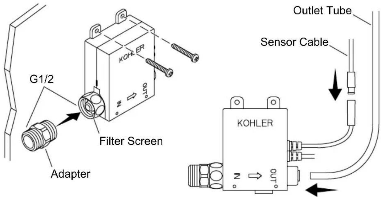
G1/2 Filter Screen Adapter KOHLER Outlet Tube Sensor Cable KOHLER OUTNOTICE: When selecting a location for the valve box, verify that all connections will be within reach.
☐ Install the valve box using appropriate anchors and fasteners for the cabinet or wall material.
☐ Verify that the filter screen is seated in the inlet on the valve box.
□ Install the adapter to the inlet on the valve box.
☐ Verify that the outlet tube from the spout is the appropriate length to reach the valve box.
☐ If necessary, cut the outlet tube. Remove any burrs and sharp edges.
☐ Insert the outlet tube into the valve box fitting until the tube stops.
□ Verify that the outlet tube is secure.
□ Connect the sensor cable from the spout to the connector on the valve box.
3. Connect the Water Supply
text_image
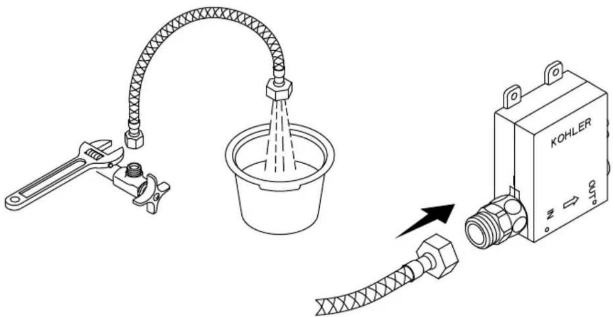
Technical diagram showing a water tap system with an adjustable arm and a KOHLER device connected to a hose, illustrating the process.
CAUTION: Risk of product damage. The supply hose must be purged of any debris before connecting to the valve box.
NOTE: To connect a hot and cold water supply, purchase the K-24154 mixing valve and refer to the “Install the Mixing Valve” section.
□ Connect the supply hose to the supply stop.
□ Direct the other end of the supply hose into a bucket.
□ Slowly open the supply stop to flush debris.
□ Continue purging until the water is clear.
□ Turn OFF the water supply.
□ Connect the supply hose to the adapter on the valve box.
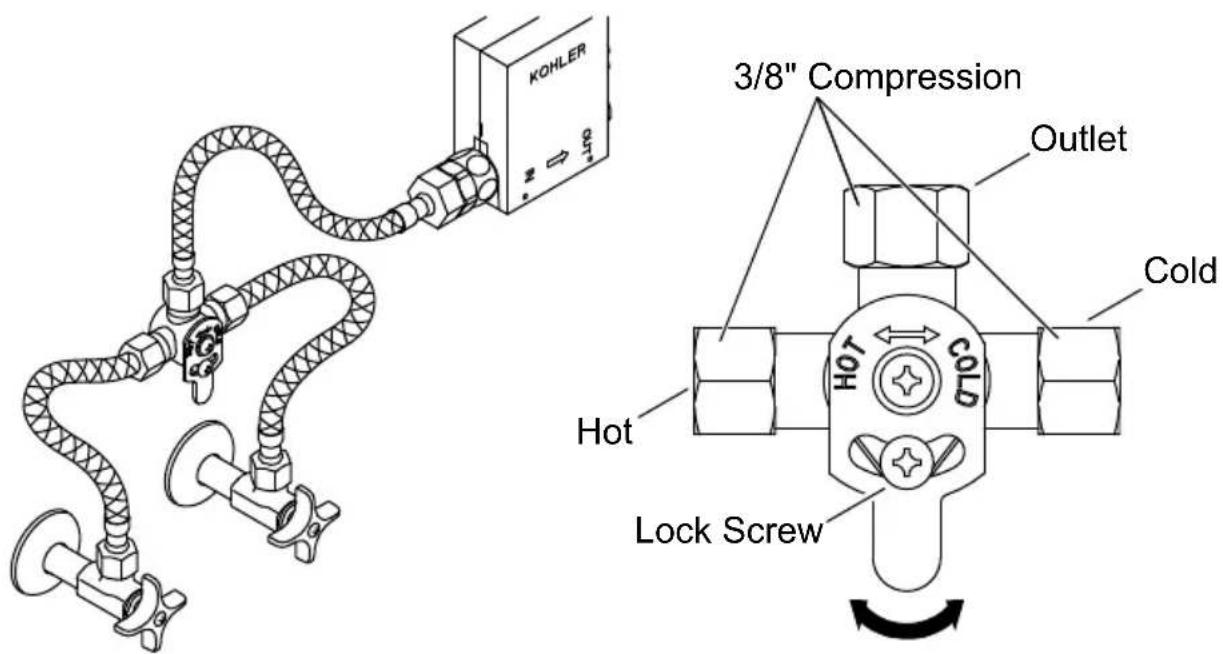
4. Install the Mixing Valve (Optional)
text_image
KOHLER 3/8" Compression Outlet Cold Hot COLD Lock Screw□ Connect the supply hose to the adapter on the valve box.
□ Connect the other end of the supply hose to the outlet on the mixing valve.
☐ Use a 3/8" compression connection (not provided) to attach the cold supply to the cold inlet on the mixing valve (marked cold on the adjustment plate).
☐ Use a 3/8" compression connection (not provided) to attach the hot supply to the hot inlet on the mixing valve (marked hot on the adjustment plate).
Temperature Adjustment
☐ Loosen the lock screw on the adjustment plate.
☐ Rotate the adjustment plate to adjust the temperature.
□ Retighten the lock screw.
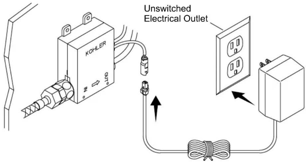
5. Install the AC Power Supply (Optional)
text_image
KOHLER OUT Unswitched Electrical OutletNOTICE: If your faucet will be powered with batteries, refer to the "Install the Batteries" section.
IMPORTANT! Do not use a switch-controlled electrical outlet (typically used for garbage disposals) to provide power to the faucet.
NOTICE: When selecting a location for the electrical outlet, verify that the AC power supply cord will reach the power cord on the valve box.
☐ Install a constant unswitched 120 VAC electrical outlet within reach of the valve box.
□ Plug the power supply (sold separately) into the electrical outlet.
□ Connect the power supply cord to the power cord on the valve box.
□ Secure any extra cord under the counter.
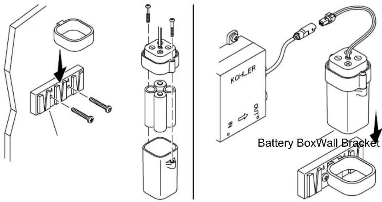
6. Install the Batteries
text_image
KOHLER Battery BoxWall BracketNOTICE: When selecting a location for the battery box, verify that the cord will reach the power cord on the valve box.
IMPORTANT! Do not use rechargeable or lithium ion batteries.
IMPORTANT! Do not mix old and new batteries.
☐ Install the wall bracket using appropriate anchors and screws (not provided) for the cabinet or wall material. Orient the bracket as shown.
□ Align the groove on the battery box holder with the slot on the wall bracket.
□ Press the battery box holder in place.
☐ Unthread the screws from the battery box to remove the cover.
☐ Insert four AA batteries in the correct orientation in the battery box.
□ Reinstall the cover. Secure with the screws.
□ Slide the battery box into the holder.
□ Connect the battery box cord to the power cord on the valve box.
text_image
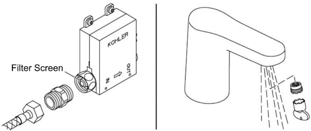
KOHLER Filter ScreenNOTE: Avoid the area in front of the sensor for 2 minutes after connections are complete. The sensor will not function correctly if triggered in the first 2 minutes. Disconnect and reconnect the power to reset the sensor.
Cleaning the Filter Screen
☐ Disconnect the supply hose and the adapter from the valve box.
□ Remove the filter screen from the valve box inlet.
□ Rinse the filter screen to remove any debris.
□ Reinstall the filter screen.
□ Reconnect the adapter and the supply hose.
Cleaning the Aerator
NOTE: The faucet is supplied with an aerator key to remove the aerator for cleaning.
□ Remove the aerator using the provided key.
□ Rinse the aerator to remove any debris.
□ Reinstall the aerator.
This troubleshooting guide is for general aid only. For service and installation issues or concerns, call 1-800-4KOHLER.
| Symptoms Probable Cause Recommended Action | ||
| 1. No water flow. | A. No batteries, or batteries installed in reverse.B. No power supply or wrong connection.C. Object in sensing range.D. Sensor lens is dirty.E. Valve filter screen is plugged. | A. Check batteries and batteries orientation.B. Check the power supply and connection.C. Remove the object.D. Wipe the sensor lens with a damp soft cloth. Wipe dry with a dry soft cloth.E. Remove and clean the valve filter screen. |
| 2. Low flow. | A. Supply pressure is low.B. Aerator is plugged.C. Valve filter screen is plugged. | A. Check that the incoming water pressure is at least 20 psi (137 kPa).B. Remove and clean the aerator. For calcium/mineral deposits, remove the plastic insert from the aerator and soak only the insert in a 50:50 mixture of vinegar and water.C. Remove and clean the valve filter screen. |
| 3. Constant water flow. | A. Solenoid is not functioning. | A. Order and install a new control valve box. |
| 4. Constant steady drip from the faucet. | A. Solenoid diaphragm is damaged. | A. Order and install a new control valve box. |
| 5. Intermittent activation. | A. Faucet is angled incorrectly to the deck or misaligned with the user area.B. Sensor lens is dirty.C. Object in the sensor area.D. Sensor lens or sensor wires are damaged. | A. Verify that the faucet is mounted according to the installation directions.B. Wipe the sensor lens with a damp soft cloth. Wipe dry with a dry soft cloth.C. Move the object away from the sensor area. Verify that the spout is positioned toward sink bowl according to the installation instructions.D. Order and install a new spout assembly. |
| 6. Sensor flashes once approximately every 2 seconds. | A. Batteries are out of power. | A. Replace the batteries. |
This device complies with Part 15 of the FCC Rules. Operation is subject to the following two conditions: (1) this device may not cause harmful interference, and (2) this device must accept any interference received, including interference that may cause undesired operation.
Changes or modifications not expressly approved by the party responsible for compliance could void the user's authority to operate the equipment.
This equipment has been tested and found to comply with the limits for a Class B digital device, pursuant to Part 15 of the FCC Rules. These limits are designed to provide reasonable protection against harmful interference in a residential installation. This equipment generates, uses, and can radiate radio frequency energy and, if not installed and used in accordance with the instructions, may cause harmful interference to radio communications.
However, there is no guarantee that interference will not occur in a particular installation. If this equipment does cause harmful interference to radio or television reception, which can be determined by turning the equipment off and on, the user is encouraged to try to correct the interference by one of the following measures:
• Reorient or relocate the receiving antenna.
- Increase the separation between the equipment and receiver.
- Connect the equipment into an outlet on a circuit different from that to which the receiver is connected.
- Consult the dealer or an experienced radio/TV technician for help.
This Class B digital apparatus complies with Canadian ICES-003.
text_image
Technical diagram showing a water tap installation and KOHLER control unit with labeled components
text_image
Technical diagram showing a water tap system with an adjustable arm and a KOHLER device connected to a hose, indicating fluid flow or installation.ES