ATTIS 650R Bronze - Computer power supply SILVERSTONE - Free user manual and instructions
Find the device manual for free ATTIS 650R Bronze SILVERSTONE in PDF.

User questions about ATTIS 650R Bronze SILVERSTONE
0 question about this device. Answer the ones you know or ask your own.
Ask a new question about this device
Download the instructions for your Computer power supply in PDF format for free! Find your manual ATTIS 650R Bronze - SILVERSTONE and take your electronic device back in hand. On this page are published all the documents necessary for the use of your device. ATTIS 650R Bronze by SILVERSTONE.
USER MANUAL ATTIS 650R Bronze SILVERSTONE
ATX Switching Power Supply 80PLUS Bronze efficiency certified
Compliant with ATX 3.1 standards and supports up to 2X power excursion
High efficiency with 80 PLUS Bronze certification
24/7 continuous power output with 50°C operating temperature
Japanese primary capacitor
Silent running 120mm fan with 18 dBA minimum
■ Multiple protection circuitry
All black flat cables
SPECIFICATION
SilverStone ATTIS Series
ATTIS 650R Bronze / ATTIS 750R Bronze
SST-AT650R-BF / SST-AT650R-BF-WBW
SST-AT750R-BF / SST-AT750R-BF-WBW
ATX Switching Power Supply 80PLUS Bronze efficiency certified
650W / 750W
This power supply is designed and manufactured according to the ATX 3 standard proposed by INTEL, This specification describes the requirements of 650W/750W Watts; switching power supply with an stretch form-factor and ATX12V,,EPS12V.,+5V standby voltage, remote on/off control, full range line input capability and forced air cooling characteristics.
1. AC INPUT
1.1 AC input requirements
The input voltage, current, and frequency requirements for continuous operation are stated below.
Table1 AC Input Line Requirements
| Parameter | Min. | Nom. | Max. | Unit |
| Vin | 90 | 100----240 | 264 | |
| Frequency | 47 | 50-60 | 63 | |
| 650W ( In ) | 10.5 | 10---5 | 4.5 | |
| 750W ( In ) | 11.5 | 11-5 | 4.5 | Arms |
VACrms Hz Arm:
Power factor correction (PF)>0.90 at full load.
2. DC OUTPUT
2.1 DC voltage regulation
| Parameter | Range | Min | Nom. | Max | Unit |
| +3.3V | +5/-5% | +3.14 | +3.30 | +3.46 | Volts |
| +5V | +5/-5% | +4.75 | +5.00 | +5.25 | Volts |
| +12V | +5/-7% | +11.16 | +12.00 | +12.60 | Volts |
| -12V | +10/-10% | -10.80 | -12.00 | -13.20 | Volts |
| +5VSB | +5/-5% | +4.75 | +5.00 | +5.25 | Volts |
2.2 Load ranges
2.2.1 (650 Watts)
| Parameter | Min | Nom. | Max | Unit |
| +3.3V | 0 | - | 20 | Amps |
| +5V | 0 | - | 20 | Amps |
| +12V | 0 | - | 54.1 | Amps |
| -12V | 0 | - | 0.3 | Amps |
| +5VSB | 0 | - | 3.0 | Amps |
(1) Maximum continuous total DC output power should not exceed 650W
(2) Maximum continuous combined load on +3.3 VDC and +5 VDC outputs shall not exceed 100W.
(3) Maximum combined current for the 12 V outputs shall be 54.1A.
2.2.2 Power Efficiency (at normal AC 115V voltage)
650W
| Voltage (V) | +12V | +5V | +3.3V | -12V | 5V | SB | efficiency |
| 100% Load(A) | 45.80 1 | 0.20 10 | .20 0.25 | 2.54 | 82% | ||
| 50% Load (A) | 22.90 5 | .10 5.10 | 0.13 | 1.27 85% | |||
| 20% Load(A) | 9.16 2.0 | 4 2.04 | 0.05 0.51 | 82% |
750W
| Voltage (V) | +12V | +5V | +3.3V | -12V | 5VSB | efficiency |
| 100% Load(A) | 53.97 10 | 0.40 10 | 40 0.26 | 2.59 | 82% | |
| 50% Load (A) | 26.99 5 | 20 5.20 | 0.13 1 | .30 85 | % | |
| 20% Load(A) | 10.79 2 | 08 2.08 | 0.05 0 | .52 82 | % |
2.2.2 Cross load setting
650W
| Range | LOAD | +12V | +5V | +3.3V | -12V | 5VSB | unit |
| 1 | +12V MAX | 54.1 | 0.5 | 0.5 | 0 | 0.1 | A |
| 2 | +5V MAX | 0.5 | 20 | 0.5 | 0.05 | 0.5 | A |
| 3 | +3.3V MAX | 0.5 | 0.5 | 20 | 0.05 | 0.5 | A |
| 4 | -12V MAX | 0.5 | 0.5 | 0.5 | 0.3 | 0.1 | A |
| 5 | +5VSB MAX | NA | NA | NA | NA | 3.0 | A |
| 6 | MIN LOAD | 0.5 | 0.5 | 0.5 | 0 | 0 | A |
750W
| Range | LOAD | +12V | +5V | +3.3V | -12V | 5VSB | unit |
| 1 | +12V MAX | 0.5 | 0.5 | 0 | 0 | 0.1 | A |
| 2 | +5V MAX | 0.5 | 20 | 0.5 | 0.05 | 0.5 | A |
| 3 | +3.3V MAX | 0.5 | 0.5 | 20 | 0.05 | 0.5 | A |
| 4 | -12V MAX | 0.5 | 0.5 | 0.5 | 0.3 | 0.1 | A |
| 5 | +5VSB MAX | NA | NA | NA | NA | 3.0 | A |
| 6 | MIN LOAD | 0.5 | 0.5 | 0 | 0 | A |
2.2 Output Ripple
2.3.1 Ripple regulation
| Parameter | Ripple& Noise | Unit |
| +3.3V | 50 | mVp-p |
| +5V | 50 | mVp-p |
| +12V | 120 | mVp-p |
| -12V | 120 | mVp-p |
| +5VSB | 50 | mVp-p |
2.3.2 Definition
The ripple voltage of the outputs shall be measured at the pins of the output connector when terminated in the load impedance specified in figure 1. Ripple and noise are measured at the connectors with a 0.1uF ceramic capacitor and a 10uF electrolytic capacitor to simulate system loading. Ripple shall be measured under any condition of line voltage, output load, line frequency, operation temperature.
2.3.3 Ripple voltage test circuit

flowchart
graph TD
    A["Power Supply\nAC Hot\nAC Neutral I"] -->|V_out| B["Load"]
    A -->|V_return| C["Scope"]
    C --> D["Ground"]
    D --> E["Capacitor 10uF 0.1uF"]
    E --> F["Resistor"]
    style A fill:#f9f,stroke:#333
    style B fill:#ccf,stroke:#333
    style C fill:#cfc,stroke:#333
    style D fill:#fcc,stroke:#333
    style E fill:#ffc,stroke:#333
    style F fill:#cff,stroke:#333
Figure 1. Ripple voltage test circuit
2.4 Overshoot
Any overshoot at turn on or turn off shall be less 10% of the normal voltage value.
2.5 +5VSB ERP
2.5.1 +5VSB ERP
When the power supply is in the standby state,
AC 115V / 60Hz, + 5 Vsb load is 0.0A, and the input power is 0.5W
AC 230V / 50Hz, + 5 Vsb load of 0.0A and input power of 0.5W
2.6 Remote ON/OFF control
When the logic level "PS-ON" is low, the DC outputs are to be enabled. When the logic level is high or open collector, the DC outputs are to be disabled.
2.7 Dynamic loading
The PSU is subjected to a load change as shown in the table below at a rate of 1A/ sec (unless otherwise specified).
The frequency of change is set to give the best readability of the deviation and setting time.
All other output loads and the AC line voltage are chosen in order to obtain the worst case condition
| Output | Load Caps [μF] (option) | Current slew rate Step Load Size (Intel) | |
| 3.3V | 8000 | 1A/μs | 30% |
| 5V | 8000 | 1A/μs | 30% |
| 12V | 10000 | 1A/μs | 60% |
of of of
3. PROTECTION
3.1 Under voltage protection.
In an under voltage fault occurs, the supply will latch all DC outputs into a shutdown state when +12V,+5V & +3.3V outputs under 60% of it's maximum value.
3.2 Over voltage protection
| output | Minimum | Nominal | Maximum |
| +12 VDC 13.4 15.0 | 15.6 Volts | ||
| +5 VDC 5.74 6.3 | 7.0 | Volts | |
| +3.3 VDC | 3.76 4.2 | 4.3 | Volts |
3.3 Short circuit protection
An output short circuit is defined as any output impedance of less than 0.1 ohms. The power supply shall shut down and latch off for shorting the +3.3 VDC,+5 VDC, or +12 VDC rails to return or any other rail. Shorts between main output rails and +5VSB shall not cause any damage to the power supply. The power supply shall either shut down and latch off or fold back for shorting the negative rails.+5VSB must be capable of being shorted indefinitely, but when the short is removed, the power supply shall recover automatically or by cycling PS_ON#. The power supply shall be capable of withstanding a continuous short-circuit to the output without damage or overstress to the unit
3.4 Over-power protection
The power supply will be shutdown and latch off when output power is 150%\~200%.
4. PCIe\* AIC Peak Power Duty Cycle test
4.1 Test Condition:
Follow as below condition table.
Duty Cycle Definition :
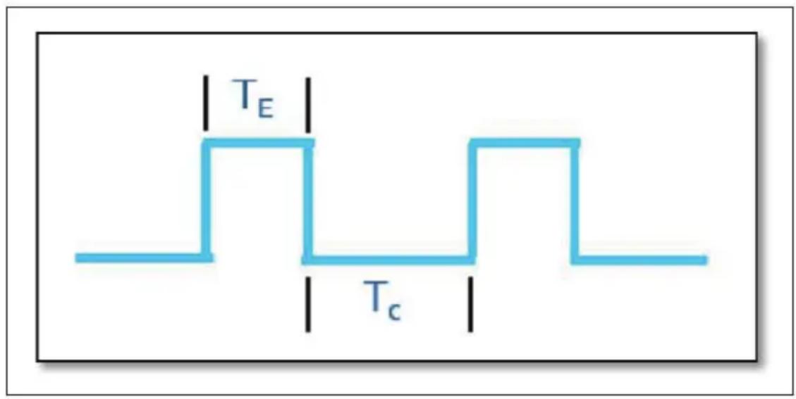
text_image
T_E T_CDuty Cycle Test Criteria for a 650W PSU – RMS
| Duty Cycle | Time Constant (TC) | Time for Power Excursion (TE) | Power @ TC Power | @ TE |
| 5% | 1900 μs | 100 μs | 596.5W | 1300 W |
| 8% | 11.5ms | 1ms | 583.3W | 1170W |
| 12.5% | 70ms | 10ms | 573W | |
| 25% 300 ms | 100 ms 600.04W | 780W |
1040W
Duty Cycle Test Criteria for a 750W PSU - RMS
| Duty Cycle | Time Constant (TC) | Time for Power Excursion (TE) | Power @ TC Power | @ TE |
| 5% | 1900 μs | 100 μs | 688.2W | 1500 W |
| 8% | 11.5ms | 1ms | 673W | 1350W |
| 12.5% | 70ms | 10ms | 661.2W | |
| 25% | 300 | ms | 100 | ms 692.8W |
4.2 Test Purpose
Simulate PSU at above table duty cycle 5%, 8%, 12.5%, 25% load situation.
Test input voltage at low line and high line, 10min test time for each Duty Cycle part.
4.3 Check&NOTES(Check and focus NOTES 2):
PSU no any shut down state and no any fault condition during the test, unless NOTES
NOTES:
- The Capacitive Load mentioned in Table 4-7 is expected to be applied to this test scenario.
- Total Test time for each Power Excursion testing time is expected to last until thermal saturation occurs in the PSU.
- More details about test time for each row above and formulas to calculate T_C and T_E power values for different PSU sizes will be detailed in the "Desktop Platform Form Factor Power Supply Test Plan – Doc #338448
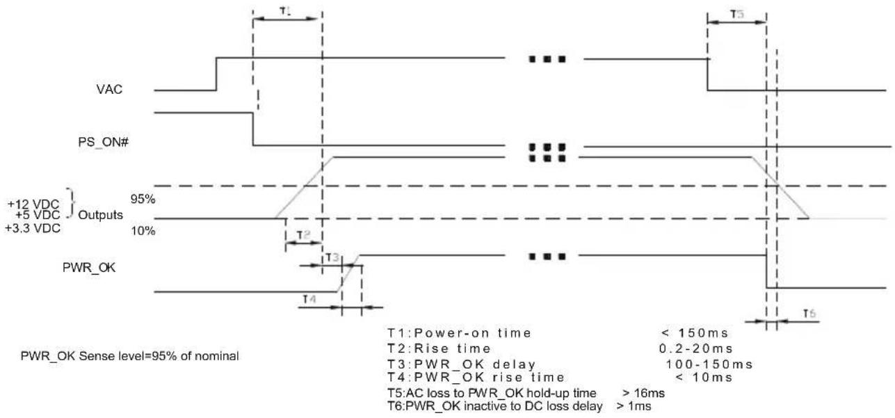
5. TIMING
5.1 Signal timing drawing
Figure 2. is a reference for signal timing for main power connector signals and rails.
other
| Signal | Time Interval | |-----------------|---------------------| | T1 | < 150ms | | T2 | 0.2-20ms | | T3 | 100-150ms | | T4 | < 10ms | | T5 | AC loss to PWR_OK hold-up time | | T6 | PWR_OK inactive to DC loss delay |Figure 2. PS-OK Timing Sequence
5.2 Hold up time
When the power loss its input power, it shall maintain 16ms in regulation limit at normal input voltage. Tested at 100% load
6. ENVIRONMENT
6.1 Operation
| Temperature 0 to 50 | °C |
| Relative Humidity | 10 to 90%, nonondensing |
6.2 Shipping and Storage
| Temperature -20 TO 70 °C | |
| Relative Humidity | 5 to 95%, non-condensing |
6.3 Altitude
| Operating | 6562 FT max |
| Storage | 10,000FT max |
7. DIMENSION
150X86X140mm
8. POWER SUPPLY CONNECTOR OVERUSE DEFINITION
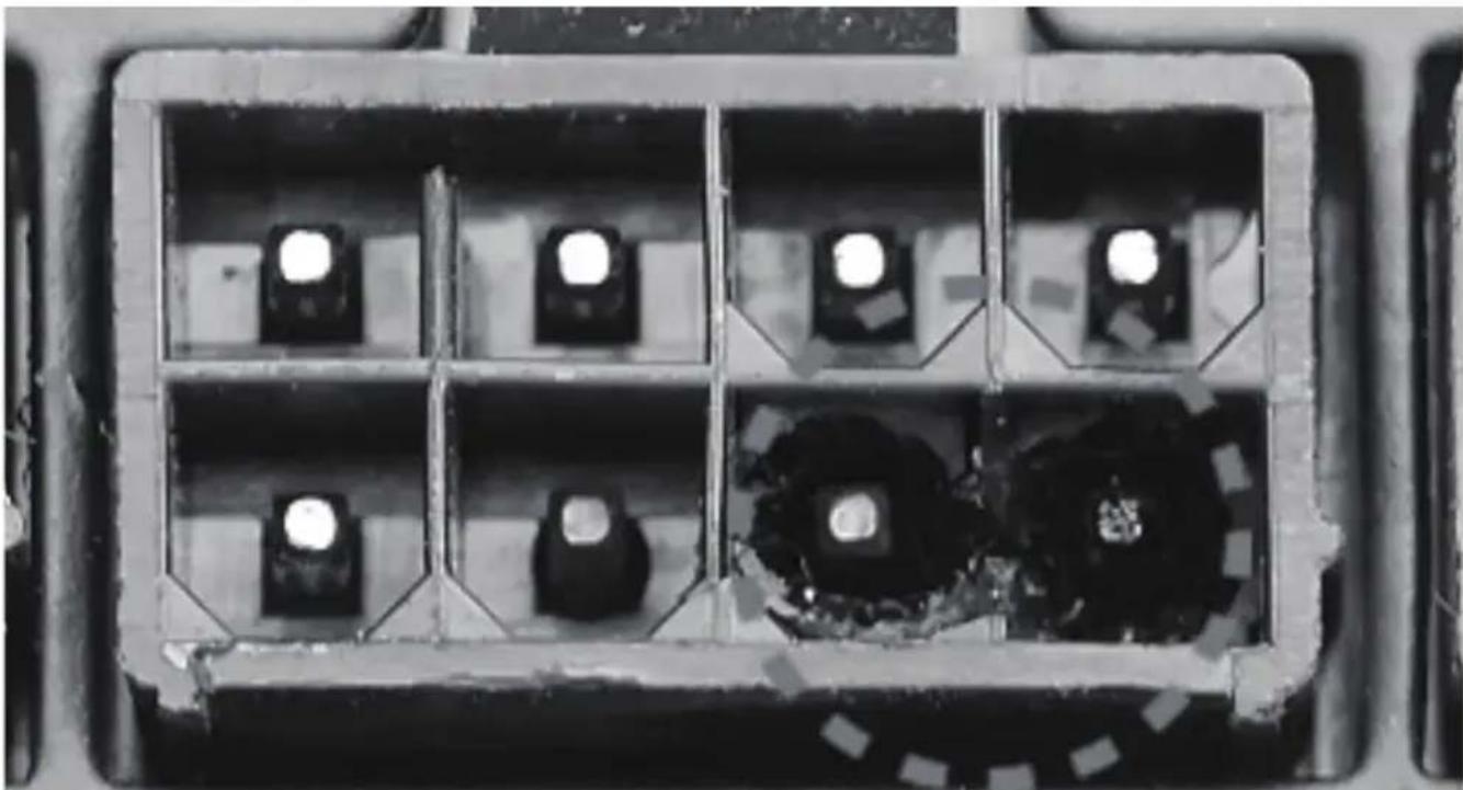
natural_image
Top-down view of a mechanical component with six internal compartments, each containing a black square and two white circular features (no text or symbols visible)EN
Power supply connector overuse definition
A single PCIe 8pin cable and connector's maximum current rating is 12.5A, which is 150W (+12V x 12.5A). So SilverStone's warranty will not cover damages or malfunction resulting from the use of a graphics card or expansion card with a single PCIe 8pin connector that exceeds standard 225W total power draw (150W from PCIe 8pin connector + 75W from PCIe motherboard slot). Similarly, a graphics card or expansion card with dual PCIe 8pin connectors that exceed 375W total power draw (300W from two PCIe 8pin connectors + 75W from PCIe motherboard slot) will also not be covered under warranty.
Peripheral (molex) or SATA connector's maximum current rating is 5A, which is 60W (+12V x 5A) or 25W (+5V x 5A). Please ensure connected devices are operating under these limits. SilverStone's warranty will not cover damages or malfunction resulting from usages exceeding these connectors and their associated cables.
24pin motherboard connector's maximum current rating for its dual +12V metal pins are 5A each, which totals 120W (+12V x 5A x 2). Please ensure +12V drawing devices connected to the motherboard are operating under these limits. SilverStone's warranty will not cover damages or malfunction resulting from usages exceeding these connectors and their associated cables.
DE
text_image
直徑不大於5mm Openings that do not exceed 5mm in any dimension 對角線不大於5mm 寬度小於1mm 則長度不限 Openings that do not exceed 1mm in width regardless of lengthhttps://www.silverstonetek.com/upload/downloads/PSU/RSD.pdf
This device complies with Part 15 of the FCC Rules.
Operation is subject to the following two conditions:
(1) this device may not cause harmful interference, and
(2) this device must accept any interference received, including interference that may cause undesired operation.
Model (safety certification): SST-AX0650FCBR-A / SST-AX0750FCBR-A
The equipment a Class | Switching Power Supply intended to use for information technology equipment or Audio and Video equipment.
Please refer to SilverStone website for latest specifications updates.
SilverStone Technology Co., Ltd.
www.silverstonetek.com
support@silverstonetek.com