
Grandia GD06 - Desktop Computer SILVERSTONE - Free user manual and instructions
Find the device manual for free Grandia GD06 SILVERSTONE in PDF.

| Product type | HTPC PC case |
| Brand | SilverStone |
| Model | Grandia GD06 |
| Dimensions (W x H x D) | 442 x 153 x 430 mm |
| Weight | 6.5 kg |
| Material | Steel and plastic |
| Motherboard compatibility | Micro-ATX, Mini-ITX |
| Power supply compatibility | ATX, max depth 150 mm |
| Hard drive bays | 2 x 3.5" hot-swappable + 1 x 3.5"/2.5" internal |
| Optical drive bays | 1 x 5.25" (slim optical drive recommended) |
| Included fans | 3 x 120 mm |
| Additional fan mounts | 2 x 80 mm |
| Dust filters | Removable filters on air intakes |
| Max CPU cooler height (with ODD) | 70 mm |
| Max CPU cooler height (without ODD) | 120 mm |
| Max PSU length | 150 mm |
| Front panel connectors | USB 3.0, audio |
| Security | Kensington lock, front door key |
| Maintenance | Clean filters every 3 to 6 months |
Frequently Asked Questions - Grandia GD06 SILVERSTONE
User questions about Grandia GD06 SILVERSTONE
0 question about this device. Answer the ones you know or ask your own.
Ask a new question about this device
Download the instructions for your Desktop Computer in PDF format for free! Find your manual Grandia GD06 - SILVERSTONE and take your electronic device back in hand. On this page are published all the documents necessary for the use of your device. Grandia GD06 by SILVERSTONE.
USER MANUAL Grandia GD06 SILVERSTONE
Designing Inspiration
natural_image
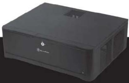
Black rectangular electronic device with ventilation slots and a logo on the front face (no visible text or symbols on body)GDO6
Grandia series
MANUAL
SilverStone Technology Co., Ltd.
www.silverstonetek.com
support@silverstonetek.com
Issue date: January, 2013
NO: G11213051
Installation and system optimization guide:
The following manual and guides were carefully prepared by the SilverStone engineering team to help you maximize the potential of your SilverStone product. Please keep this manual for future reference when upgrading or performing maintenance on your system. A copy of this manual can also be downloaded from our website at:
http://www.silverstonetek.com
natural_image
Black rectangular electronic device with ventilation slots and a logo (no visible text or symbols on body)Specification P.2
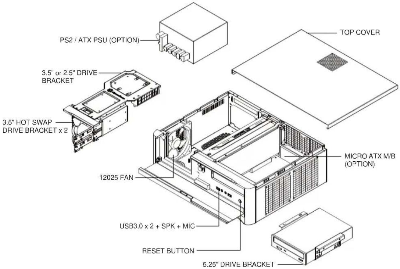
Disassemble chart P.3
Installation guide P.4
Connector definition P.17
Front I/O connector guide P.18
Component size limitations P.18
Recommended cooling device setup & selection—— P.24
Fan & fan filter disassembly guide P.26
Dual purpose space P.29
Expansion card removal guide P.30
Protect your computer P.32
Q&A P.34
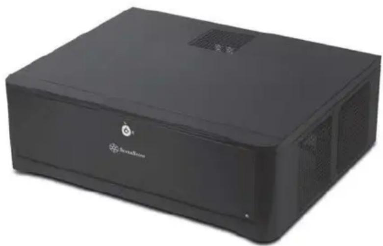
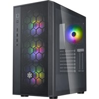
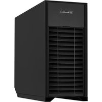
GD06
Stunning HTPC chassis with impressive cooling and storage capability
natural_image
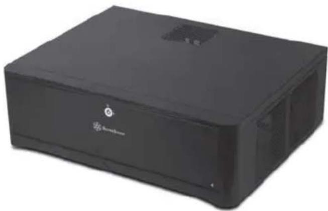
Black rectangular electronic device with a logo on the front face (no visible text or symbols on body)Specification
| Material | Aluminum front door and plastic front panel, 0.8mm SECC body | |
| Motherboard | Micro ATX, Mini-DTX, Mini-ITX | |
| Model No. | SST-GD06B (Black) | |
| Drive Bay | External | 5.25" x 1 |
| Internal | 3.5" x 4, 2.5" x 1 or 3.5" x 3, 2.5" x 2 | |
| Cooling System | Right Side | 2 x 120mm intake fans, 1200rpm, 20dBA |
| Left Side | 1 x 120mm intake fan, 1200rpm, 20dBA(Also compatible with 80mm fan) | |
| Rear | 2 x 80mm fan slots (optional mounting) | |
| Expansion Slot | 5 | |
| Front I/O Port | USB 3.0 x 2audio x 1MIC x 1 | |
| Power Supply | Support standard PS2 (ATX) up to 150mm | |
| Expansion Card | Support graphic cards up to 11 inches | |
| Dimension | 440 mm (W) x 150 mm (H) x 340 mm (D) | |
| PICTURE | ITEM | PURPOSE | QTY |
| [20X3] | METAL SPACER | SECURE MOTHERBOARD | 2 |
| [WDB1] | SCW-HW-6-32 | SUCURE POWER SUPPLY OR PSU PKT AND MOTHERBOARD | 13 |
| [KICK] | SCW-HDD-6-32 | SECURE 3.5"HARD DRIVE | 4 |
| [036K] | SCW-PW-M3 | SECURE 2.5" DRIVE | 8 |
| [2WZ4] | FAN CABLE | LINK FANS TO POWER SUPPLY | 1 |
| [007X] | BUNCH WIRE TIES | SECURE WIRE | 5 |
 | PSU RUBBER | REDUCE PSU VIBRATION | 4 |
| [HDDH] | MANUAL | INSTALLATION GUIDE | 1 |
 | KEY | LOCK FRONT DOOR | 2 |
| [48H1] | USB ADAPTER | USB3.0 TO USB2.0 COVERTOR CABLE | 1 |
| [A706] | SCW-TF-M3 | SECURE OPTICAL DRIVE | 4 |
| [CS26] | SCW-TF-6-32 | SECURE 3.5" HARD DRIVE IN 5.25" DRIVE BRACKET | 4 |
Installation Guide
Before you begin, please make sure that you.
(1) have all components collected.
(2) check that all components do not have compatibility problems with each other or with the case.
(3) if possible, assemble the components outside the case first to make sure they are working.
(4) keep the motherboard manual ready for reference during installation.
(5) prepare a Philips screwdriver.
1
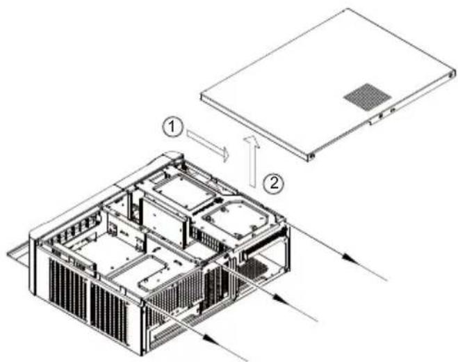
ENGLISH
Unscrew the three screws from the rear of the chassis then remove the top cover.
DEUTSCH
natural_image
Isometric technical diagram of a server rack with ventilation ducts and mounting brackets (no text or labels)ENGLISH
Unscrew four screws holding the optical drive bracket to remove it.
DEUTSCH
natural_image
Isometric technical diagram of a server rack with internal components and two vertical arrows indicating flow or movement (no text or labels present)ENGLISH
Unscrew two screws from the center brace to remove it.
DEUTSCH
natural_image
Isometric technical diagram of a server room with multiple internal compartments and ventilation ducts (no text or labels)ENGLISH
Remove the screws from the hard drive bracket to remove it.
DEUTSCH
natural_image
Isometric diagram of a mechanical component with a vertical force arrow and base blocks (no text or symbols)ENGLISH
Adhere the included power supply feet to the end of the power supply for support.
DEUTSCH
Install power supply into the case. Please note the case supports mounting power supply in two different orientations. (For more information regarding power supply size limitations, please refer to the component guide in later pages).
DEUTSCH
natural_image
Isometric technical diagram of a server rack with ventilation ducts and internal components (no text or labels)ENGLISH
Insert the I/O shield included with your motherboard, then install the motherboard into the case.
DEUTSCH
natural_image
Close-up of a computer case with exposed cables and connectors (no visible text or symbols)ENGLISH
We recommend at this point to start thinking about routing the cables cleanly before connecting them to the motherboard, cables include fan cables, power supply 24pin cable, CPU ATX 4pin/EPS12V 8pin, front panel connectors, and front I/O connectors.
DEUTSCH
natural_image
Isometric technical drawing of a building interior with structural details and an inset circular detail showing a road or pipeline (no text or symbols present)ENGLISH
The tray areas around the motherboard have many small pass-through holes that can be used with included wire tie, please refer to the illustration for more information.
DEUTSCH
natural_image
Close-up of electronic equipment with visible wiring and connectors (no readable text or symbols)ENGLISH
Please connect all the SATA (or IDE) cables to the motherboard as required by your system.
DEUTSCH
natural_image
Interior view of a black server rack with internal components and cables (no visible text or labels)ENGLISH
Now carefully count and separate the required power cables for your hard drive, optical drive, and graphics card. Place the needed cables out of the case and neatly place the unneeded power cables into available space inside the case.
DEUTSCH
natural_image
Interior view of a computer case with exposed cables and a central component (no visible text or symbols)ENGLISH
The available free space in front of the motherboard and power supply has plenty of room for any excess cables to be stored and tied down using the included wire ties.
DEUTSCH
flowchart
graph TD
    A["Start"] --> B["Assembly Step 1"]
    B --> C["Assembly Step 2"]
    C --> D["Assembly Step 3"]
    D --> E["Assembly Step 4"]
ENGLISH
Install and secure any 3.5" or 2.5" hard drive into the hard drive bracket with screws. The purpose of using screws for hard drive installation is to ensure complete isolation of hard drive from the bracket to maximize the vibration dampening pad's effectiveness.
DEUTSCH
natural_image
Technical illustration of a server rack with internal components and mounting holes, showing exterior view (no text or symbols)ENGLISH
There is a rubber partition plate in the rear part of the hard drive bracket designed for channeling airflow to the top panel vents. This plate has small flaps that can be removed if needed to create additional room for cables.
DEUTSCH
natural_image
Technical line drawing of a computer tower internal structure with ventilation fans and drive bays (no text or labels)ENGLISH
Reinstall the hard drive bracket, connect the cables, and secure with screws.
DEUTSCH
natural_image
Diagram of a device with cables and connectors, no text or symbols presentENGLISH
Install and secure 3.5"hard drive into the hard drive bracket with screws. If the first PCI-E slot was occupied, please use the 90 degree SATA and power cables.
DEUTSCH
natural_image
Isometric line drawing of a device with two input/output lines and internal components (no text or symbols)ENGLISH
Install and secure the optical drive onto the optical drive bracket.
DEUTSCH
natural_image
Close-up of an electronic device with visible wiring and circuit board (no text or symbols)ENGLISH
There are pass-through holes next to the optical drive bracket for tidying hard drive or power cables using wire ties.
DEUTSCH
natural_image
Technical line drawing of a computer chassis with visible internal components and mounting brackets (no text or symbols)ENGLISH
Reinstall the center brace back into the case.
DEUTSCH
natural_image
Technical line drawing of a computer chassis with ventilation ducts and mounting bracket (no text or symbols)ENGLISH
Please remove 5.25" drive bay cover and then secure the optical drive bracket with screws.
DEUTSCH
natural_image
Isometric technical diagram of a computer chassis with internal components and a vertical load arrow (no text or symbols)ENGLISH
Install and secure required expansion cards.
DEUTSCH
natural_image
Technical line drawing of a computer tower internal unit with ventilation grilles and fan blades (no text or labels)ENGLISH
Place the top cover back onto the case and secure with three screws.
DEUTSCH
natural_image
Technical line drawing of a computer chassis with an inset showing a component (no text or symbols present)ENGLISH
Install the hard drive into the hot-swappable drive racks and place the front cover back.
DEUTSCH
natural_image
Isometric line drawing of a computer tower case with ventilation grilles and drive bays (no text or labels)FRANÇAIS
natural_image
Isometric line drawing of a rectangular electronic device with ventilation grilles and a vented top (no text or symbols)ENGLISH
Installation complete.
DEUTSCH
Connector definition
(1) Front panel connector installation
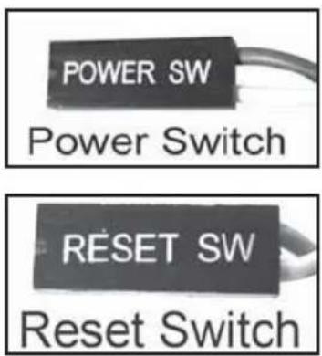
ENGLISH
Power switch and reset switch installation guide:
Please refer to the motherboard manuals for the motherboard's "Front Panel Connector" or "System Panel Connector" pin definition. Power switch and reset switch have no polarity, so they can be connected in any orientation.
DEUTSCH
ENGLISH
LED connector installation guide:
Please refer to the motherboard manuals for the motherboard's "Front Panel Connector" or "System Panel Connector" pin definition. ; the white wires are negative while other colors are positive wires. The Power LED wires are separate pins for compatibility with different motherboard pin definition so please make sure they are connected in the right polarity by referring to your motherboard manual.
DEUTSCH
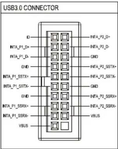
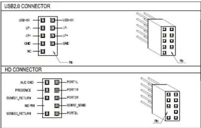
Front I/O connector guide
ENGLISH
Below are the front I/O connectors pin definition, please also check your motherboard manual to cross reference with motherboard's front I/O pin headers. SilverStone's I/O connectors are in block type to simplify installation.
DEUTSCH
The GD06 was designed to be as small as possible while maximizing interior space usage, please refer to the following guidelines for component selection and future upgrade considerations.
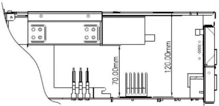
CPU cooler height limitation
ENGLISH
When optical drive is used, the GD06 has 70mm height limitation for CPU cooler. If no optical drive is installed, the height limit for CPU cooler increases to 120mm. If a silent CPU cooling solution is required, we recommend using the SilverStone NT01-E in fanless configuration for 65W rated or lower CPUs. If you need more space for a larger CPU cooler, we recommend using SilverStone's TS03 (only accepts slim optical drive).
DEUTSCH
Power supply length limitation
The allowable power supply length is determined by the left intake fan size. Please refer to the table below as a guide when choosing the appropriate power supply.
ENGLISH
A. Depth limitation
The GD06 supports power supply with depth of up to 150mm.
The modular cable power supply might interfere with the hot-swappable hard drive racks. Please make sure they will not interfere with each other. We recommend installing SilverStone's ST50F-P (140mm deep) power supply upside-down.
B: Cable length recommendations:
Below is a table of recommend cable length based off of common retail power supplies. Please make sure that the power supply you want to use has long enough cables to fit the below recommendations or you can also choose to purchase additional power cable extensions.
The table shows the length recommended for a power supply with cables coming out from the right side of the power supply casing (with the power supply's 120mm fan facing down):
DEUTSCH
A. Maximaltiefe
| Cable type and location | Minimum length |
| EPS 8pin/ATX4pin (over the motherboard) | 400mm |
| EPS 8pin/ATX4pin (in front of the motherboard) | 670mm |
| ATX 24Pin(over the motherboard) | 300mm |
| ATX 24Pin(in front of the motherboard) | 350mm |
| SATA 15Pin to optical drive | 550mm |
| SATA 15Pin to hard drive on optical drive bracket | 330mm |
| SATA 15Pin to left front 2.5" drive | 100mm |
| SATA 15Pin to left rear 3.5" drive | 150mm |
| 4-Pin Peripheral to hot-swap drive | 0mm |
Graphics card/expansion card length limitation GD06 can support 11" (280mm) consumer level graphics cards
Graphic card length reference:
AMD Radeon HD 5870 11"
AMD Radeon HD 6870 10.5"
NVIDIA GeForce GTX580 - 10.5"
NVIDIA GeForce GTX480 - 10.5"
AMD Radeon HD 5850 - 9.5"
NVIDIA GeForce GTX470 - 9.5"
AMD Radeon HD 6850 9"

natural_image
Interior view of a computer tower case showing internal components like CPU, drive, and motherboard (no visible text or labels)Memory / RAM module height limitation
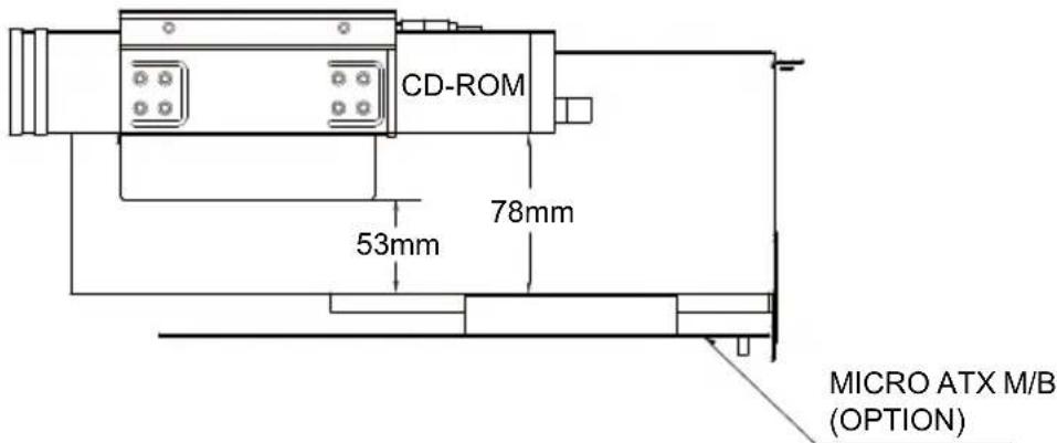
ENGLISH
From the motherboard to the optical cage with a 3.5" hard drive, the maximum height of the DRAM modular is 53mm. The maximum height will extend to 78mm if you choose not to install a 3.5" hard drive.
DEUTSCH
A. The maximum clearance between the optical drive and the inner part of the front door is 18.8mm.
B. The maximum size of a USB device that can be inserted into the front USB port is 16mm.
DEUTSCH
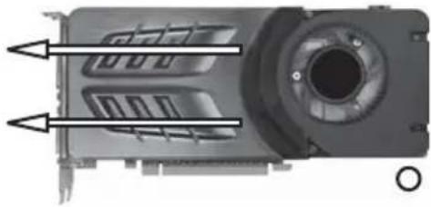
Recommended cooling device setup and selection
When choosing a graphics card, we recommend models that have fan blowing exhaust air to the rear slot, this will ensure smooth and efficient airflow within the GD06 for maximum cooling performance.
natural_image
Close-up of a mechanical component with internal channels and mounting holes (no visible text or symbols)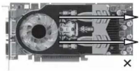
natural_image
Close-up of a computer motherboard with visible CPU socket and ventilation slots (no text or symbols)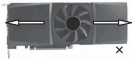
natural_image
Diagram of a fan blade with directional arrows indicating flow or movement (no text or symbols)ENGLISH
When choosing a graphics card, we recommend models that have fan blowing exhaust air to the rear slot, this will ensure smooth and efficient airflow within the GD06 for maximum cooling performance.
DEUTSCH
natural_image
Interior view of a computer motherboard showing CPU socket, motherboard board, and motherboard with visible slots and wiring (no text or symbols)ENGLISH
We placed pass-through holes in various spots such as around the motherboard, in front of the power supply, and next to the hard drive, etc. Please use wire ties in places as needed by your hardware configuration.
DEUTSCH
SilverStone already includes three 120mm low noise fans in the GD06. The fans are selected to maintain class-leading cooling performance while keeping noise to minimum. If you wish to increase air exhaust speed around the CPU, there are two 80mm fan slots for adding additional fans. For this, we recommend the use of SilverStone's SUSCOOL81.
DEUTSCH
natural_image
Black-and-white photo of a SUSCOOL81 CPU fan with attached cable (no text or symbols on the fan itself)Cleaning of fan filters on a regular basis is highly recommended
natural_image
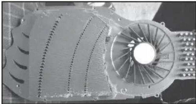
Close-up of a mechanical fan or turbine component with visible blades and central hub (no text or symbols)ENGLISH
GD06's positive air pressure design is an effective configuration that will reduce dust buildup inside the case. Small air particles or lint will accumulate over time on GD06's intake filters instead of on the components inside the case. To maintain GD06's excellent cooling performance for years to come, we recommend to clean all fan filters regularly every three months or half a year (depending on your environment). Below are steps to remove fan filters.
DEUTSCH
Upgrade and maintenance
Fan and fan filter disassembly guide
If you need to change fans, clean filters, or upgrade a fan, please refer to the following steps:
ENGLISH
Refer to the case installation guide to properly remove the drive bracket, then loosen the fan screws to remove the fans.
DEUTSCH
ENGLISH
If the CPU cooler obstruct you from removing the right rear fan, please remove the right front fan first and slide the rear one to the front to remove it.
DEUTSCH
natural_image
Technical line drawing of a mechanical fan assembly with directional arrows indicating motion (no text or symbols)ENGLISH
Loosen the screws holding the fan filter to the fan to remove the fan filter.
РУССКИЙ
natural_image
Technical line drawing of a computer tower with ventilation ducts and mounting holes (no text or symbols)ENGLISH
To remove the power supply fan filter, flip the case upside-down then loosen the screws holding the fan filter to remove it.
РУССКИЙ
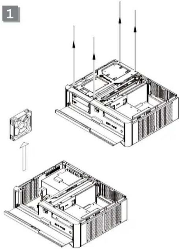
There is a dual purpose space located above the power supply area, it can be used for either of the two following application:
A
natural_image
Exploded view diagram of a server rack system showing internal components and mounting brackets (no text or labels)ENGLISH
Installation of a 3.5" hard drive
DEUTSCH
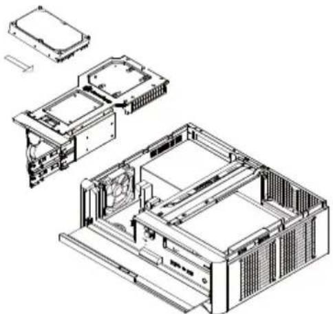
natural_image
Exploded view diagram of a computer chassis showing internal components and assembly (no text or labels)ENGLISH
Installation of a slot device or short expansion card such as extra motherboard I/O, fan controller, or daughter board (e.g. ASUS Xonar HDAV1.3) plus one 2.5" hard drive. Extra power supply rubber feet are included for providing support to expansion card installed above the power supply.
DEUTSCH
Expansion card removal guide
Although GD06's interior space is designed tightly, you can still install expansion cards without having to remove other brackets. Please refer to the following scenarios: (with the top cover already removed)
ENGLISH
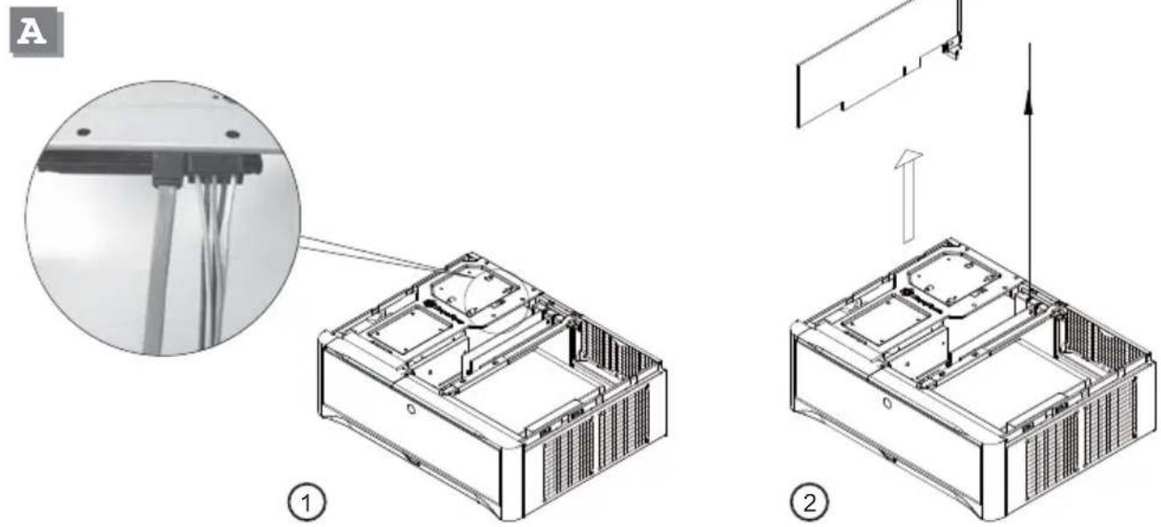
If the rear hard drive's cables are blocking the left expansion card, please first unplug the hard drive cables then proceed to remove/install the expansion card. Make sure to plug the cables back into the hard drive after installation.
DEUTSCH
natural_image
Technical line drawing of a mechanical device with internal components and an upward arrow indicating motion (no text or symbols)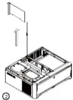
natural_image
Technical line drawing of a mechanical device with internal compartments and an external panel (no text or symbols)ENGLISH
If the expansion card on the right side is blocked by the card to the left, please first remove the card on the left side to allow the card on the right side to be removed without taking the center brace off the case.
DEUTSCH
Protect your computer
Front door lock

natural_image
Cartoon illustration of a businessman running while holding a key, wearing a padlock with a smiling face (no text or symbols)ENGLISH
We suggest using the key locks on the front door to protect your hard drive. The optical drive, USB ports, and Reset button will be inaccessible when the front door is locked, so please keep the two keys in a safe place. If you happen to lose your keys, please contact a technical locksmith for help.
DEUTSCH
ENGLISH
Connect the Kensington lock to the Kensington Security Slot of GD06 to ensure security for the installed drives and system. (The Kensington lock is optional)
DEUTSCH
natural_image
Two black electronic connectors with ports and connectors, no visible text or symbols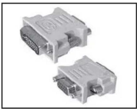
natural_image
Two DVI connectors with visible pin labels, no text or symbols presentQ:
ENGLISH
I found that the GD06 is too large to fit in my home theater cabinet after installing the display output adapter. How can I solve this problem?
DEUTSCH
natural_image
Black cable with two connected connectors (no text or symbols visible)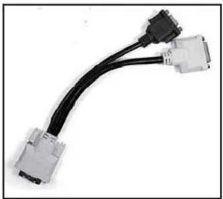
natural_image
Coiled black cable with two connected DVI connectors (no text or symbols visible)A:
ENGLISH
Please use the adapter cable as a replacement for the display output adaptor. The cable can be bent in any direction to ensure that the GD06 fits comfortably inside your home theater cabinet.
DEUTSCH
How to install an optical drive in GD06 with NT06-E?
DEUTSCH
The TS03 supports slim optical drive to reduce the depth required in the 5.25" optical drive bay. It can increase the space for CPU cooler in the GD06. The limitations of installing NT06-E into the GD06 are as follow :
DEUTSCH
The distance from CPU to motherboard edge.
59.5mm < x < 96.5mm
98mm < y < 117.5mm
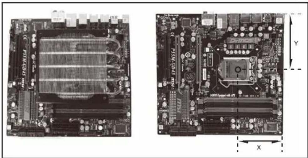
natural_image
Two views of a computer motherboard showing internal components and circuitry (no text or symbols visible)Horizontal orientation of CPU cooler on the motherboard.
The distance from CPU to motherboard edge.
55.5mm < x < 68mm
69.5mm < y < 89mm
ENGLISH
The above limitations apply only if graphics card is installed in the first expansion slot and with rear 80mm fans installed. If fans are removed, y distance decreases by 25mm. If graphics card is installed in the second expansion slot, the x distance increases by 20mm.
DEUTSCH
natural_image
Close-up of a computer motherboard with visible circuitry and connectors (no text or symbols)ENGLISH
Install the NT06-E on the motherboard.
DEUTSCH
natural_image
Two gray rectangular electronic devices with internal slots, shown against a white background (no text or symbols visible)ENGLISH
Insert a slim optical drive into the TS03.
DEUTSCH
natural_image
Interior view of an open computer case showing internal circuit board and ventilation duct (no visible text or labels)ENGLISH
Install the motherboard into the chassis.
DEUTSCH
natural_image
Interior view of an open computer case showing internal components like CPU socket and motherboard (no visible text or symbols)ENGLISH
Install and secure the TS03 in the 5.25" drive bay.
DEUTSCH
natural_image
Interior view of a computer tower case showing internal circuitry and ventilation ducts (no text or symbols visible)ENGLISH
Connect the wires and cables to the TS03.
DEUTSCH
natural_image
Interior view of a computer tower case showing internal fan and circuit board (no visible text or symbols)ENGLISH
Install a 120mm fan over the NT06-E as needed.
DEUTSCH
Warranty Information
This product has a limited 1 year warranty in North America and Australia.
For information on warranty periods in other regions, please contact your reseller or SilverStone authorized distributor.
Warranty terms & conditions
- Product component defects or damages resulted from defective production is covered under warranty.
Defects or damages with the following conditions will be fixed or replaced under SilverStone Technology's jurisdiction.
a) Usage in accordance with instructions provided in this manual, with no misuse, overuse, or other inappropriate actions.
b) Damage not caused by natural disaster (thunder, fire, earthquake, flood, salt, wind, insect, animals, etc...)
c) Product is not disassembled, modified, or fixed. Components not disassembled or replaced.
d) Warranty mark/stickers are not removed or broken.
Loss or damages resulted from conditions other than ones listed above are not covered under warranty.
2. Under warranty, SilverStone Technology's maximum liability is limited to the current market value for the product (depreciated value, excluding shipping, handling, and other fees). SilverStone Technology is not responsible for other damages or loss associated with the use of product.
3. Under warranty, SilverStone Technology is obligated to repair or replace its defective products. Under no circumstances will SilverStone Technology be liable for damages in connection with the sale, purchase, or use including but not limited to loss of data, loss of business, loss of profits, loss of use of the product or incidental or consequential damage whether or not foreseeable and whether or not based on breach of warranty, contract or negligence, even if SilverStone Technology has been advised of the possibility of such damages.
4. Warranty covers only the original purchaser through authorized SilverStone distributors and resellers and is not transferable to a second hand purchaser.
5. You must provide sales receipt or invoice with clear indication of purchase date to determine warranty eligibility.
6. If a problem develops during the warranty period, please contact your retailer/reseller/SilverStone authorized distributors or SilverStone http://www.silverstonetek.com.
Please note that: (i) You must provide proof of original purchase of the product by a dated itemized receipt; (ii) You shall bear the cost of shipping (or otherwise transporting) the product to SilverStone authorized distributors. SilverStone authorized distributors will bear the cost of shipping (or otherwise transporting) the product back to you after completing the warranty service; (iii) Before you send the product, you must be issued a Return Merchandise Authorization ("RMA") number from SilverStone. Updated warranty information will be posted on SilverStone's official website. Please visit http://www.silverstonetek.com for the latest updates.
Additional info & contacts
For North America (usasupport@silverstonetek.com)
SilverStone Technology in North America may repair or replace defective product with refurbished product that is not new but has been functionally tested. Replacement product will be warranted for remainder of the warranty period or thirty days, whichever is longer. All products should be sent back to the place of purchase if it is within 30 days of purchase, after 30 days, customers need to initiate RMA procedure with SilverStone Technology in USA by first downloading the "USA RMA form for end-users" form from the below link and follow its instructions.
http://silverstonetek.com/contactus.php
For Australia only (support@silverstonetek.com)
Our goods come with guarantees that cannot be excluded under the Australian Consumer Law.
You are entitled to a replacement or refund for a major failure and for compensation for any other reasonably foreseeable loss or damage.
You are also entitled to have the goods repaired or replaced if the goods fail to be of acceptable quality and the failure does not amount to a major failure.
Please refer to above "Warranty terms & conditions" for further warranty details.
SilverStone Technology Co., Ltd. 12F No. 168 Jiankang Rd., Zhonghe Dist., New Taipei City 235 Taiwan R.O.C. + 886-2-8228-1238 (standard international call charges apply)
For Europe (support.eu@silverstonetek.de)
For all other regions (support@silverstonetek.com)

- Designing Inspiration
- GDO6
- Grandia series
- GD06
- Specification
- Installation Guide
- 1
- ENGLISH
- DEUTSCH
- FRANÇAIS
- Connector definition
- Front panel connector installation
- Front I/O connector guide
- Recommended cooling device setup and selection
- Cleaning of fan filters on a regular basis is highly recommended
- Upgrade and maintenance
- РУССКИЙ
- Expansion card removal guide
- Protect your computer
- Q:
- A:
- Warranty Information
- Warranty terms & conditions
- Additional info & contacts
Brand : SILVERSTONE
Model : Grandia GD06
Category : Desktop Computer