
Mammoth MM01 - Desktop Computer SILVERSTONE - Free user manual and instructions
Find the device manual for free Mammoth MM01 SILVERSTONE in PDF.

| Product Type | Computer Case (System Unit) |
| Brand | SilverStone |
| Model | Mammoth MM01 |
| Form Factor | Full Tower |
| Material | Steel |
| Motherboard Compatibility | SSI EEB, SSI-CEB, ATX, Extended ATX |
| Included Fans | 2x 180mm Air Penetrator AP182, adjustable speed 500-1800 RPM |
| Air Filter | HEPA filter + removable pre-filter |
| Power Supply | Not included, recommended max size 220 mm (up to 285 mm) |
| 5.25" Drive Bays | Yes |
| 3.5" Hard Drive Bays | Yes |
| 2.5" Hard Drive Bays | Yes |
| Max Graphics Card Length | 338 mm (13.3") |
| Max CPU Cooler Height | 183 mm |
| Additional Features | Hot-swap support (with CP05), liquid cooling support, tool-free installation |
| Maintenance | Clean the pre-filter every 3 to 6 months; replace the HEPA filter if necessary |
| Included Accessories | Manual, screws, brackets |
Frequently Asked Questions - Mammoth MM01 SILVERSTONE
User questions about Mammoth MM01 SILVERSTONE
0 question about this device. Answer the ones you know or ask your own.
Ask a new question about this device
Download the instructions for your Desktop Computer in PDF format for free! Find your manual Mammoth MM01 - SILVERSTONE and take your electronic device back in hand. On this page are published all the documents necessary for the use of your device. Mammoth MM01 by SILVERSTONE.
USER MANUAL Mammoth MM01 SILVERSTONE
natural_image
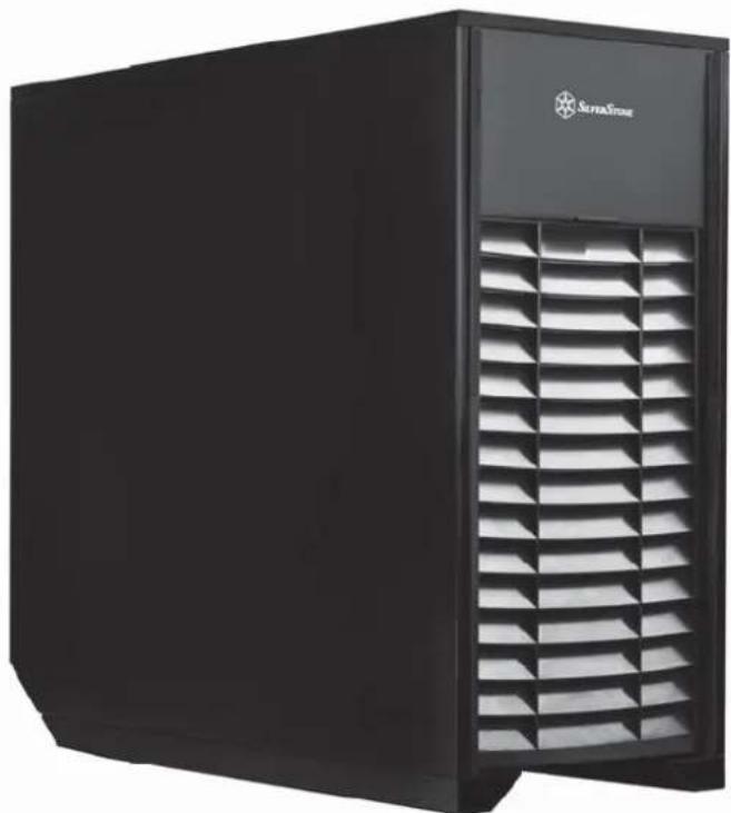
Exterior view of a black SuperStone air purifier unit with ventilation grilles (no visible text or symbols)Professional chassis with integrated HEPA filter for harsh or critical environments

bar
| Category | Value | |---|---| | Category 1 | 100 | | Category 2 | 100 | | Category 3 | 100 | | Category 4 | 100 | | Category 5 | 100 | | Category 6 | 100 | | Category 7 | 100 | | Category 8 | 100 | | Category 9 | 100 | | Category 10 | 100 | | Category 11 | 100 | | Category 12 | 100 | | Category 13 | 100 | | Category 14 | 100 | | Category 15 | 100 | | Category 16 | 100 | | Category 17 | 100 | | Category 18 | 100 | | Category 19 | 100 | | Category 20 | 100 | | Category 21 | 100 | | Category 22 | 100 | | Category 23 | 100 | | Category 24 | 100 | | Category 25 | 100 | | Category 26 | 100 | | Category 27 | 100 | | Category 28 | 100 | | Category 29 | 100 | | Category 30 | 100 | | Category 31 | 100 | | Category 32 | 100 | | Category 33 | 100 | | Category 34 | 100 | | Category 35 | 100 | | Category 36 | 100 | | Category 37 | 100 | | Category 38 | 100 | | Category 39 | 100 | | Category 40 | 100 | | Category 41 | 100 | | Category 42 | 100 | | Category 43 | 100 | | Category 44 | 100 | | Category 45 | 100 | | Category 46 | 100 | | Category 47 | 100 | | Category 48 | 100 | | Category 49 | 100 | | Category 50 | 100 | | Category 51 | 100 | | Category 52 | 100 | | Category 53 | 100 | | Category 54 | 100 | | Category 55 | 100 | | Category 56 | 100 | | Category 57 | 100 | | Category 58 | 100 | | Category 59 | 100 | | Category 60 | 100 | | Category 61 | 100 | | Category 62 | 100 | | Category 63 | 100 | | Category 64 | 100 | | Category 65 | 100 | | Category 66 | 100 | | Category 67 | 100 | | Category 68 | 100 | | Category 69 | 100 | | Category 70 | 100 | | Category 71 | 100 | | Category 72 | 100 | | Category 73 | 100 | | Category 74 | 100 | | Category 75 | 100 | | Category 76 | 100 | | Category 77 | 100 | | Category 78 | 100 | | Category 79 | 100 | | Category 80 | 100 | | Category 81 | 100 | | Category 82 | 100 | | Category 83 | 100 | | Category 84 | 100 | | Category 85 | 100 | | Category 86 | 100 | | Category 87 | 100 | | Category 88 | 100 | | Category 89 | 100 | | Category 90 | 100 | | Category 91 | 100 | | Category 92 | 100 | | Category 93 | 100 | | Category 94 | 100 | | Category 95 | 100 | | Category 96 | 100 | | Category 97 | 100 | | Category 98 | 100 | | Category 99 | 100 | | Total (Total) |Installation and system optimization guide:
The following manual and guides were carefully prepared by the SilverStone engineering team to help you maximize the potential of your SilverStone product. Please keep this manual for future reference when upgrading or performing maintenance on your system. A copy of this manual can also be downloaded from our website at: http://www.silverstonetek.com
● Product Overview P.1
- Specifications P.2
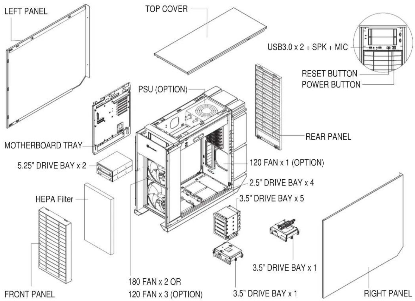
● Disassemble Chart P.3
- Installation Guide P.5
- Connector Definition P.17
● Front I/O connector Guide P.19
● Component Size limitations P.20
● CPU And Graphic Card Supporter P.29
● Optimal Thermal Performance Layout P.33
- Upgrade And Maintenance P.39
● Q&A P.47
● Warranty Information P.55
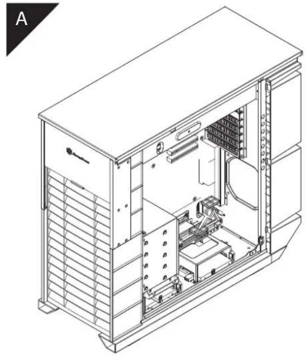
- Introduction
For computer designers, creating a chassis capable of surviving harsh environments is a tough task, especially if dust is a major problem. Most resort to fanless configuration as this eliminates the possibility of dust buildup introduced by active airflow into the chassis, which is the main cause of system overheating over time. But limited heat dissipation capacity afforded by fanless designs confines systems to lower powered CPUs and Mini-ITX boards with less features.
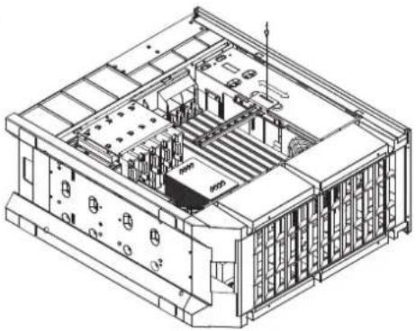
To overcome this limitation, SilverStone's R&D team once again challenged and overturned convention by coming up with an answer in the Mammoth MM01 chassis. Instead of completely sealing off airflow to prevent dust, the MM01 has a partially-sealed design with active filtering. To prevent dust from entering the chassis, a HEPA filter is used to cover the air intake area, making MM01 the first retail computer chassis to incorporate this internationally recognized filtering technology. Used frequently by clean room in factories, operating room in hospitals, or facilities requiring dust-free environment, the HEPA filter has the ability to remove airborne particles far exceeding what's available in traditional computer equipments. In order for this to work without suffocating airflow, two Air Penetrator fans were selected for use in the MM01. With a combined rating of up to 340CFM, they provide air pulling power similar to typical household fans and make it possible to maintain proper cooling for high-end components despite the presence of highly restrictive HEPA filters.
Complementing the tremendous ability to keep dust at bay, the MM01 also has unique, downward slanting front and rear vents to keep liquid from flowing in from the top of the chassis. This simple, yet affective design helps MM01 take on much harsher conditions required by professionals working in places not normally suitable for computers. For those choosing to use MM01 in normal home or office, its superior filtering could potentially help clean up the working environment as well!
natural_image
Black server unit with ventilation grilles and 'SuperStone' logo on top (no readable text beyond branding)- Specifications
| Material | Aluminum door, plastic anti-splash grille, steel panels and body |
| Model | SST-MM01B (black) |
| Motherboard | SSI-EEB, SSI-CEB, Extended ATX, ATX, Micro-ATX |
| Drive Bay | Exposed 5.25" x 2Internal 3.5" x 7 ( hot-swap x1 ), 2.5" x 4 |
| Cooling System | Front 2 x AP182 180mm intake fan 500~1800rpm*, 17~42 dBA1 x 120mm fan slotRear |
| Expansion Slot | 8 |
| Front I/O Port | USB 3.0 x 2 audio x 1 MIC x 1 |
| Power Supply | 1 x Optional standard PS2 (ATX) no length limitation |
| Expansion Card | Compatible up to 13.3" long, width restriction-6.69" |
| Limitation of CPU cooler | 183mm |
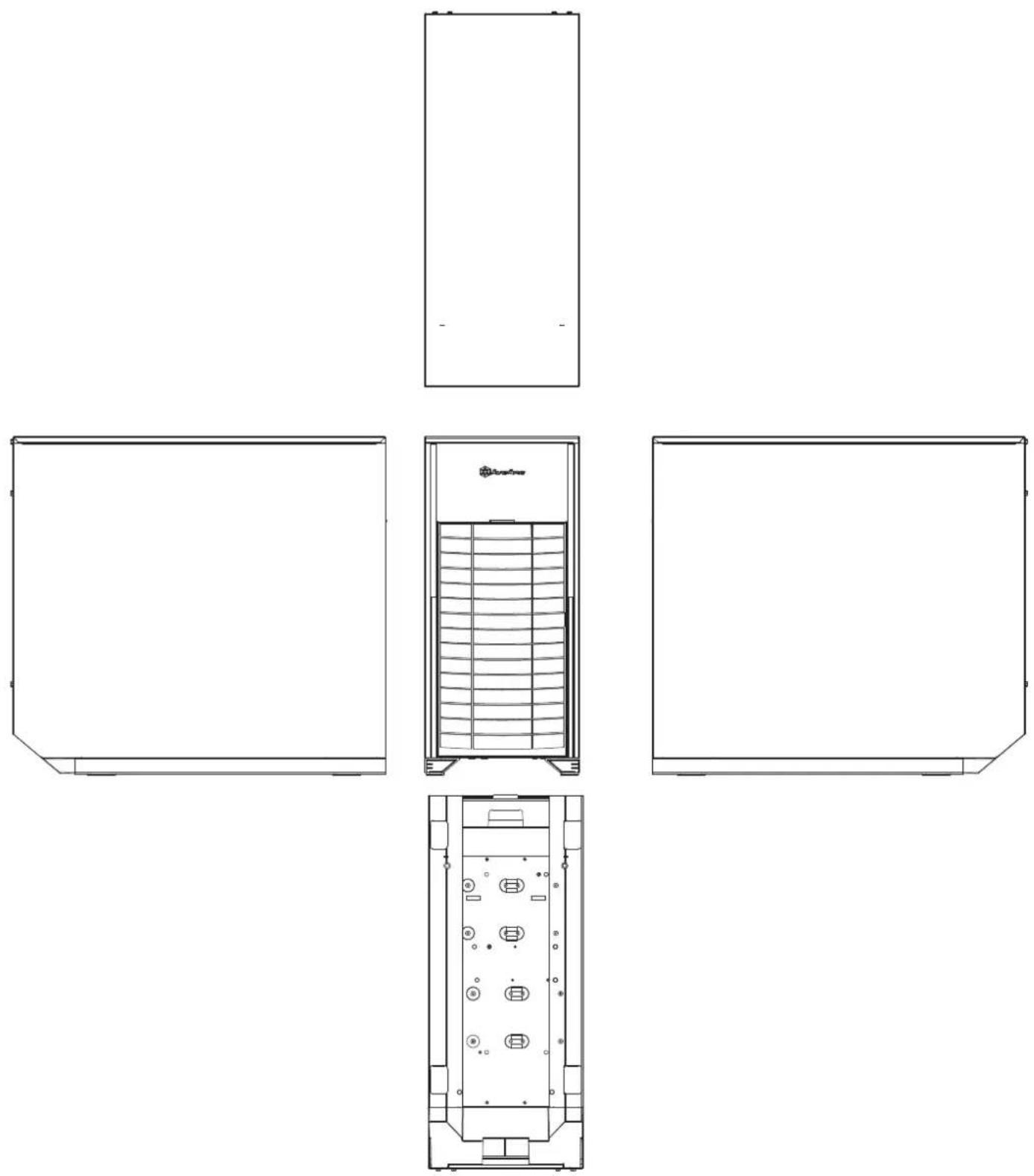
| Dimension | 271mm (W) x 542mm (H) x 597mm (D), 87.69 liters |
| Extra | Includes HEPA filter |
*AP182's original top speed is 2000rpm, but high resistance introduced by HEPA filter reduces top speed by 200rpm.
| PICTURE ITEM PURPOSE | |||
| SCREW - P - M3 * 4 - BK | Secure 2.5" HDD | ||
| SCREW - THUMB - M3 * 6 - BK | Secure optical drives | ||
| SCREW - THUMB - 6 - 32 * 6 - BK | Secure VGA holder and claw | ||
| SCREW - I - 6 - 32 * 5 - BK | Secure PSU, 12025 fan, motherboard and 3.5" HDD | ||
| STANDOFF - 6 - 32* 6.5H - 6 - 32 | Motherboard standoff | ||
 | VGA - SUPPORT - HOLDER | VGA supporter holder | |
| VGA - SUPPORT - CLAW | VGA supporter claw | ||
| STANDOFF - SOCKET - WRENCH | Standoff socket wrench | ||
| BUNCH - WIRE - TIES | Cable management | ||
Before you begin, please make sure that you
① have all components collected
② check that all components do not have compatibility problems with each other or with the case
③ if possible, assemble the components outside the case first to make sure they are working
④ keep the motherboard manual ready for reference during installation
natural_image
Technical line drawing of a modular device with internal structure and directional arrows indicating flow or movement (no text or symbols)ENGLISH
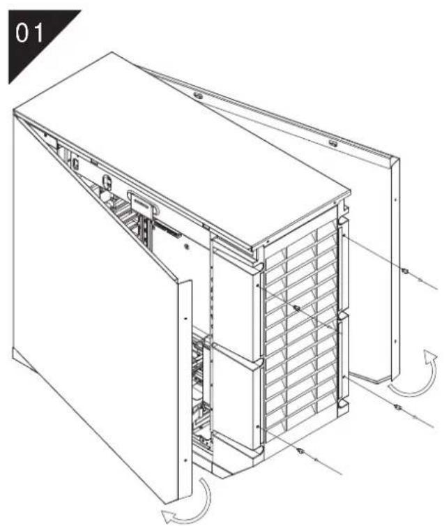
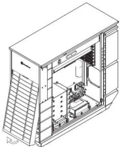
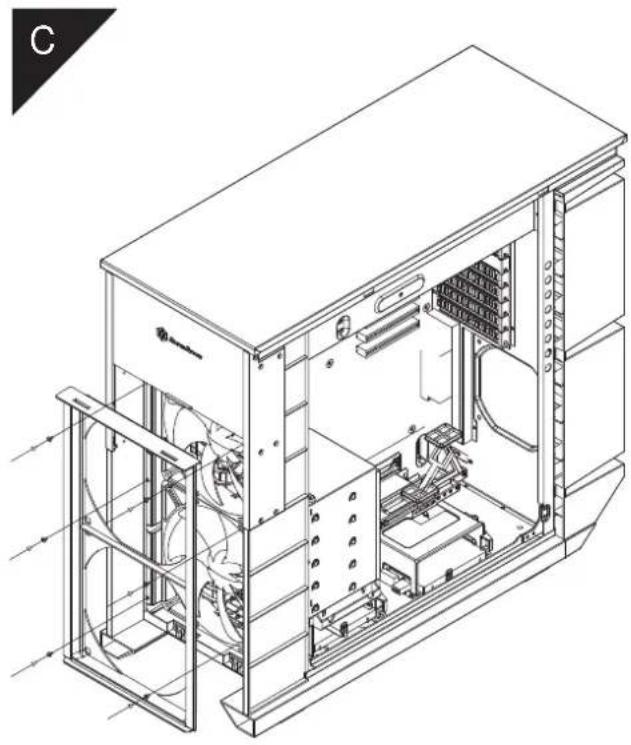
Loosen two screws from both left and right side panels to remove them.
DEUTSCH
natural_image
Technical line drawing of an internal server rack unit with visible internal components and mounting brackets (no text or labels)ENGLISH
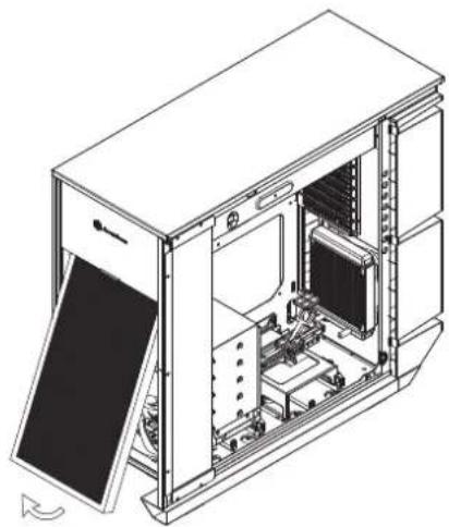
Remove top panel by pushing it toward the rear.
DEUTSCH
natural_image
Technical line drawing of a computer tower internal structure showing ventilation duct and fan (no text or labels)ENGLISH
Loosen three screws holding the motherboard tray to remove it.
DEUTSCH
natural_image
Technical line drawing of an internal computer case with visible structural components and ventilation ducts (no text or labels)ENGLISH
Insert the power supply from the top, if the power supply has a build-in 120mm fan or larger, we recommend installing the power supply with its fan facing down.
DEUTSCH
natural_image
Technical line drawing of an internal server rack with visible internal compartments and mounting points (no text or labels)ENGLISH
Remove 3.5" drive cage.
DEUTSCH
natural_image
Technical line drawing of a computer tower internal structure showing fan, drive, and ventilation components (no text or labels)ENGLISH
Loosen the screws holding the lower drive cages to remove them.
DEUTSCH
natural_image
Technical line drawing of an internal server rack with visible wiring and connections (no text or labels)ENGLISH
Install 2.5" drive into the bottom of the chassis and secure with screws.
DEUTSCH
natural_image
Technical line drawing of an internal server or rack unit with visible internal components and ventilation ducts (no text or labels)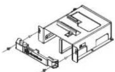
ENGLISH
Reinstall the lower drive cage. If you want to utilize CP05, you can install it now.
DEUTSCH
natural_image
Technical line drawing of a server rack with ventilation grilles and a mesh cover (no text or symbols)ENGLISH
Install motherboard rear I/O plate into the chassis.
DEUTSCH
natural_image
Technical line drawing showing a computer motherboard with internal components and an arrow indicating assembly (no text or symbols present)ENGLISH
Install motherboard onto the motherboard tray. If you have already installed a large CPU cooler on the motherboard, we recommend connecting ATX12V 4pin or EPS 8pin cables from your power supply to the motherboard now to make installation easier later on.
DEUTSCH
natural_image
Close-up of electronic equipment components including a circuit board, connectors, and a meshed device (no visible text or symbols)ENGLISH
Reinstall the assembled motherboard tray back into the chassis. If you have either the ATX12V 4pin or EPS 8pin cables connected, please make sure to have it pass through the opening between power supply and the motherboard compartment.
DEUTSCH
natural_image
Close-up of a computer motherboard with CPU socket, RAM slots, and visible circuitry (no readable text or symbols)ENGLISH
We recommend that you start cable manage now and connect cables such as the ATX 24pin, front I/O connectors, and any other connectors from front panel devices.
DEUTSCH
natural_image
Close-up of a dark mechanical component with a woven strap hanging through a circular opening, no visible text or symbols.ENGLISH
Route all power supply cables to the opening on the left of the power supply.
DEUTSCH
natural_image
Isometric line drawing of a multi-tiered server rack or rack unit with multiple parallel lines and connectors (no text or symbols)ENGLISH
Install 3.5" hard drives into the drive cage.
DEUTSCH
natural_image
Technical line drawing of a server rack cabinet with internal components and ventilation ducts (no text or labels)ENGLISH
Install hard drive cage back into the case with cables routed.
DEUTSCH
natural_image
Technical line drawing of an internal mechanical or electronic device assembly (no text or symbols visible)ENGLISH
Remove the 5.25" drive bay covers to install required 5.25" devices.
DEUTSCH
natural_image
Close-up of a computer motherboard with visible CPU socket and cable routing (no text or symbols)ENGLISH
Connect all cables for 5.25", 3.5", and 2.5" drives as needed..
DEUTSCH
natural_image
Technical line drawing of a server rack with meshed panels and ventilation grilles (no text or symbols)ENGLISH
Remove expansion slot covers to install required expansion cards. Unused slots should have covers installed.
РУССКИЙ
natural_image
Technical line drawing of an industrial machine casing with internal components and mounting brackets (no text or symbols)ESPAÑOL
natural_image
Technical line drawing of an internal server rack with visible internal components and mounting brackets (no text or labels)ENGLISH
Insert 3.5" hard drive into the lower hard drive cage
DEUTSCH
natural_image
Technical line drawing of an internal server rack unit with visible internal components and a directional arrow (no text or labels)ENGLISH
Reinstall the top panel.
DEUTSCH
natural_image
Technical line drawing of a modular server or rack unit with internal structure and directional arrows indicating flow (no text or symbols)ENGLISH
Reinstall both left and right side panel to complete installation.
DEUTSCH
Connector definition
(1) Front Panel Connector installation

ENGLISH
Power switch and reset switch installation guide:
Please refer to the motherboard manuals for the motherboard's "Front Panel Connector" or "System Panel Connector" pin definition.
Power switch and reset switch have no polarity, so they can be connected in any orientation.
DEUTSCH
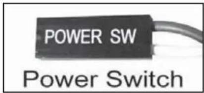
(1) Front Panel Connector installation
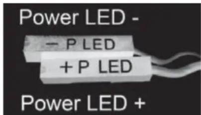
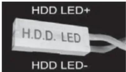
ENGLISH
Please refer to the motherboard manuals for the motherboard's "Front Panel Connector" or "System Panel Connector" pin definition.; the white/black wires are negative while other colors are positive wires. The Power LED wires are separate pins for compatibility with different motherboard so please make sure they are connected in the right polarity by referring to your motherboard manual.
DEUTSCH
(2) Front I/O connector guide
ENGLISH
Below are the front I/O connectors pin definition, please also check your motherboard manual to cross reference with motherboard's front I/O pin headers. MM01's I/O connectors are in block type to simplify installation.
DEUTSCH
Component Size Limitations
The MM01 can accommodate all standard size components and even some that are out of spec, please refer to the following guidelines for component selection and future upgrade considerations:
(1) CPU cooler height limitation
natural_image
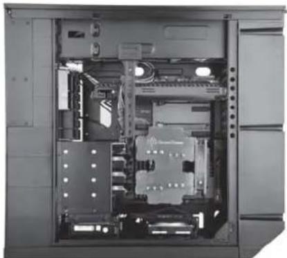
Interior view of a computer tower case showing internal components like CPU, memory, and drive rails (no text or labels visible)ENGLISH
The height limit is 183mm and there is 13mm of clearance around the motherboard's top edge. The clearance toward the front of the case is variable depending on how much you fill the hard drive cage. There is 223mm of clearance from the end of an installed hard drive to the motherboard minus a approximately 11mm for a 90 degree angled SATA connector (less room with 180 degree connectors). If you intend to fill the drive cage, please install CPU fan on the rear side of the CPU cooler as shown in the photo illustration to avoid interference.
DEUTSCH
Component Size Limitations
(2) Power supply and optical drive limitation
ENGLISH
A: Length limitation
The Total length for power supply and optical drive: Power supply and the optical drive space in the MM01 share the same plane so the total limit is 439mm including possible room for cables. We recommend maximum size for power supply of up to 220mm such as the SilverStone's ST1500. Maximum length limitation for PSU only is 285mm.
DEUTSCH
Component Size Limitations
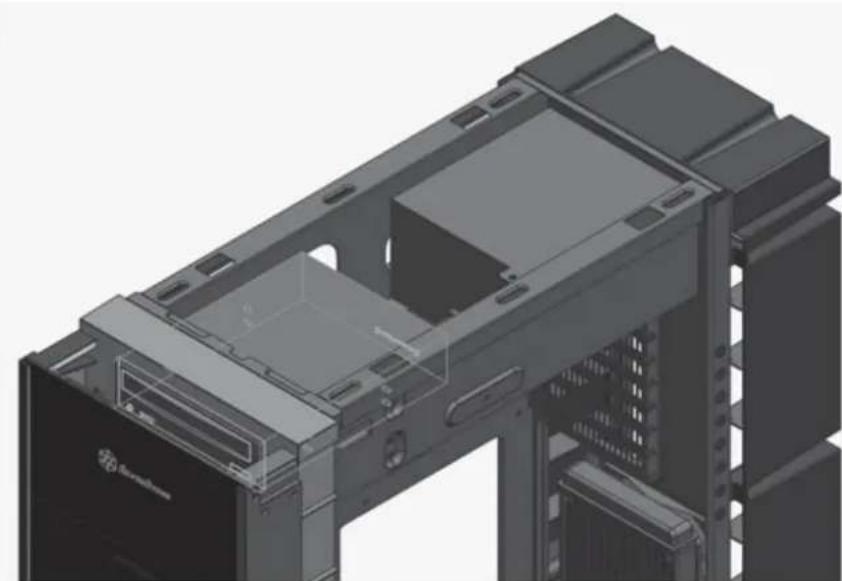
natural_image
3D technical illustration of a computer chassis with internal components and mounting hardware (no text or symbols visible)ENGLISH
The absolute maximum length for optical drive is 225mm. Once the optical drive length surpasses 225mm, it will start to encroach the cable routing hole to the right of the power supply compartment.
DEUTSCH
Component Size Limitations
(2) Power supply and optical drive limitation
ENGLISH
B: Power supply cable length recommendation
Below is the recommended cable length for retail ATX motherboards. If the cables are not long enough, please purchase extension cables.
DEUTSCH
| Cable type and location | Minimum length |
| EPS 8pin/ATX4pin (from left side of PSU) | 530mm |
| ATX 24Pin (from left side of PSU) | 300mm |
| SATA 15Pin (from left side of PSU to top opticaldrive) | 50mm |
| SATA 15Pin (from left side of PSU to bottom most3.5" hard drive) | 430mm |
| SATA 15Pin (from left side of PSU to 2.5" harddrive) | 600mm |
| PCIE 8/6pin (to first expansion slot) | 380mm |
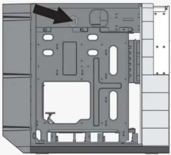
natural_image
Interior view of a computer drive bay with labeled components and an arrow indicating a specific part (no text or symbols present)ENGLISH
When using a non-modular PSU with a depth of 140mm, route the CPU 8/4 Pin through the indicated hole first. PP07 extension cables can be used if the cable is not long enough
DEUTSCH
Component Size Limitations
(3) Graphics card/expansion card length limitation
natural_image
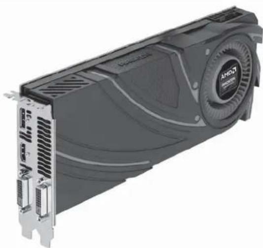
Exterior view of a AMD CPU GPU card with visible internal components and ventilation slots (no text or symbols on the device itself)ENGLISH
MM01 can support 13.3"(338mm) consumer level graphics cards.
DEUTSCH
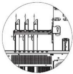
There is 61mm of distance between the motherboard to the hard drive. If you use a memory similar to the one shown in the illustration, please remove the heatsink on it prior to installation.
DEUTSCH
natural_image
Close-up of a black DDR/DDR478 memory chip with visible pins and branding (no readable text beyond branding)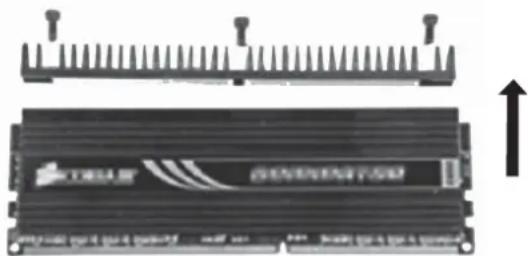
natural_image
Diagram of a black RAM module with a bracket and an upward arrow, no visible text or symbols(5) Motherboard size limitation
natural_image
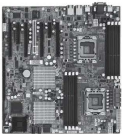
Top-down view of a computer motherboard showing CPU socket, RAM slots, and various processor racks (no text or labels visible)
ENGLISH
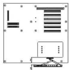
MM01 supports up to SSI-EEB (Extended ATX motherboard). New generation of SSI-CEB server or workstation motherboards no longer require CPU cooler mounting holes on the motherboard tray. Coolers can now be installed directly on the motherboard. As a result, we eliminated support for SSI-CEB CPU cooler mounting holes and instead increased the large gap on the motherboard tray to support CPU cooler back plates swapping with more LGA 1150/1155 motherboards. The MM01 chassis' support for new and future SSI-CEB motherboards should be unaffected by this change.
Note: MM01 has standard screw hole for motherboards and does not include additional screw hole that some server motherboards require.
DEUTSCH
CPU And Graphic Gard Supporter
a
natural_image
Technical line drawing of a computer tower internal structure showing ventilation, cooling fan, and drive unit (no text or labels)b
natural_image
Technical line drawing of a mechanical assembly inside a circular frame (no text or symbols)C
natural_image
Technical line drawing of a mechanical assembly or enclosure with no visible text or symbolsd
natural_image
Diagram of a device with a rack-mounted unit and a control panel, enclosed in a circle (no text or symbols)e
natural_image
Technical line drawing of an internal server rack with multiple drive bays and ventilation slots (no text or labels)f
natural_image
Pure electrical circuit lines without any symbols(1): CPU Cooler Supporter
ENGLISH
a. First set the chassis on its side, make sure it is on a level surface.
b. The CPU supporter has already been installed in a commonly used position. You can loosen the screw in the middle to fully extend it.
c. If the supporter position is not optimal for your setup, remove two more screws on left and right side to move the supporter. After finding the optimal position for your setup, secure with screws.
d.Move the supporter arm up to touch the installed CPU cooler and then secure the middle screw.
e. Place the chassis upright to let the CPU cooler rest naturally on the supporter.
f. Recommended usage range for supporter:
From 13mm beyond edge of the motherboard to 45mm inward from the motherboard edge.
Most 120mm fan based tower-style CPU cooler should be compatible.
DEUTSCH
CPU And Graphic Card Supporter
ESPAÑOL
natural_image
Technical line drawing of an internal server or rack unit with ventilation ducts and mounting holes (no text or labels)b
natural_image
Isometric technical drawing of a multi-level industrial or mechanical assembly with no visible text or symbolsC
natural_image
Technical line drawing of a mechanical assembly with no visible text or symbols(2): Graphic card supporter
ENGLISH
a. First set the chassis on its side, make sure it is on a level surface.
b. Install VGA supporter onto the chassis and adjust it to avoid power connectors on the graphic card.
c. Install clips onto the VGA supporter according to the installed slot.
Note: if more than one graphic card is installed, avoid installing them adjacent to each other as the clip may not fit between two adjacent graphic cards.
DEUTSCH
CPU And Graphic Card Supporter
繁體中文
natural_image
Close-up of a heat sink with cooling fins and cooling tower (no text or symbols visible)ENGLISH
If you are installing a tower-style CPU cooler, we recommend that the CPU fan blows rearward to work with MM01's overall airflow.
DEUTSCH
natural_image
Illustration of a MRI scanner with cooling fan and drive unit (no text or symbols visible)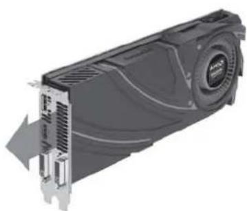
natural_image
Illustration of a computer hard drive (PCI) with cooling fan and ventilation slots, shown in 3D rendering without any text or symbols.ENGLISH
When choosing a graphics card, we recommend models that have fan blowing exhaust air to the rear slot, this will ensure smooth and efficient airflow within the MM01 for maximum cooling performance.
DEUTSCH
Please refer to the following diagrams
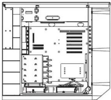
a. There are plenty of cable tie bridges behind the motherboard tray, which you can utilize to organize cables.
b. The illustration explains which cables the openings are designed for cable placements, the illustration are based on most common motherboard designs
c. There is less than 10mm gap between the front edge of motherboard tray and left side panel. The gap between the top of the 5.25" drive tray and the top cover is also less than 10mm. These were designed as part of structure strengthening areas and are not made for storing cables and connectors so please don't use these small gaps for cable routing to avoid damage.
d. If multiple hard drives are installed, we recommend using CP06-E to ease cable routing.
DEUTSCH
Please refer to the following diagrams
C
natural_image
Close-up of a car's front panel showing a charging plug and battery, with a white X symbol on the wall (no text or symbols on the main subject)
natural_image
Close-up of a mechanical component with a circular hole and internal cavity, showing no visible text or symbols.d
natural_image
Two black cable connectors labeled CP06-E4 and CP06-E2, shown without any text or symbols on the cables themselves.
natural_image
Close-up of a black industrial electrical panel with multiple metal components and screws (no visible text or symbols)Mammoth Series MM01
Optimal Thermal Performance Layout
(4) Fan Speed Adjustment
natural_image
Technical line drawing of a server rack unit with front panel and side view indicators (no text or symbols)ENGLISH
MM01's Air Penetrator fans are speed adjustable between 500rpm\~1800rpm. The speeds are designed for silent or performance usage.
DEUTSCH
As of 2014, the MM01 is equipped with the best available 180mm fan on the market in AP182 so there is no need for upgrade. SilverStone does offer three retail 180mm fans for replacement or downgrade as option. Thermal performance is not always directly related to overall airflow, in most situations, Air Penetrator fan's air focusing design is most optimal for use in the MM01.
DEUTSCH
Upgrade And Maintenance
(1) Fan filter removal guide
natural_image
Close-up of a mechanical fan assembly with visible blades and internal components (no text or symbols)ENGLISH
MM01's positive air pressure design is an effective configuration that will reduce dust buildup inside the case. Small air particles or lint will accumulate over time on intake filters instead of on the components inside the case. To maintain MM01's cooling performance and lengthen HEPA's filter usage life, we recommend cleaning MM01's pre-filter regularly every three months or half a year (depending on your environment). Below are steps to remove fan filters.
DEUTSCH
Upgrade And Maintenance
A
natural_image
Technical line drawing of a server rack unit with internal components and ventilation ducts (no text or labels)B
natural_image
Technical line drawing of a computer tower case with internal components and a slide on the left (no text or symbols)ENGLISH
HEPA filter cannot be cleaned, it can only be replaced
Figure A: Grab hold of the bottom front panel and pull to remove pre-filter
Figure B: Remove HEPA filter
To purchase a retail fan filter as an upgrade or replacement in the event of loss, damage or simply as a backup, you can search on our website for the nearest resellers or distributor: http://www.silverstonetek.com/wheretobuy_all.php
DEUTSCH
Upgrade And Maintenance
簡体中文
HEPA滤网无法清理,只能直接更换。
图A:按住前面板底部,拉出初级滤网
图B:移除HEPA滤网
添购滤网:
natural_image
Technical line drawing of an electronic device housing with mounting brackets and internal components (no text or symbols)ENGLISH
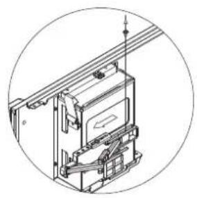
CP05 and CP05-SAS can be purchased separately if you wish to have hot-swap function. Please note the following:
A. If you need to swap hard drives while running an operating system (hot-swap), you need to make sure the SATA chipset (or motherboard southbridge) used to connect to hard drives has proper support and driver to do so. For more information on how to setup your system for hot-swap hard drives, please refer to the video at this link: http://www.youtube.com/watch?v=NoNiEMPnSEk
B. Once you have successfully set up hot-swap functionality in your system, we recommend using separate power cables for system drive and data drives. It is best to use hot-swap function on data drives and connect system drive directly to SATA 15 Pin connector. (Ignore this if you are using CP05-SAS)
DEUTSCH
(3) Front fan removal
natural_image
Technical line drawing of an internal server rack unit with visible circuitry and mounting brackets (no text or labels)ENGLISH
Remove both right and left side panels.
DEUTSCH
natural_image
Technical line drawing of a server rack unit with internal components and ventilation ducts (no text or labels)ENGLISH
Remove all filters
DEUTSCH
Upgrade And Maintenance
natural_image
Technical line drawing of a server rack unit with internal components and ventilation ducts (no text or symbols)ENGLISH
Loosen screws holding the HEPA filter bracket to remove it.
DEUTSCH
natural_image
Technical line drawing of an internal server or rack unit with fan blades and ventilation ducts (no text or symbols)ENGLISH
Loosen screws holding the fan to remove it.
DEUTSCH
natural_image
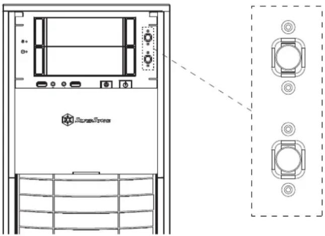
Technical line drawing of a server rack unit with ventilation grilles and control panel (no text or symbols)ENGLISH
Loosen screws holding the fan speed switch, then route the switch through the hole on front panel. (Note: please use a small screwdriver for this)
DEUTSCH
natural_image
Technical line drawing of an internal server rack unit with visible circuit breakers and mounting brackets (no text or labels)ENGLISH
To reinstall the fan, simply follow the steps in reverse
DEUTSCH
Upgrade And Maintenance
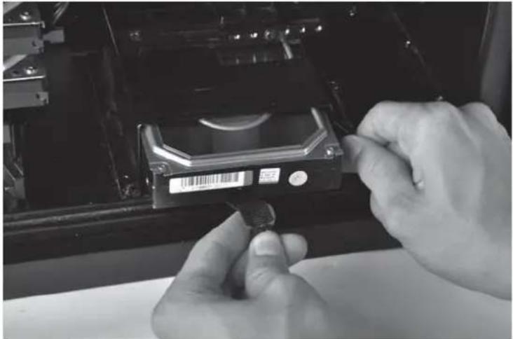
(4) Bottom hard drive removal guide
natural_image
Close-up of hands installing a CD drive into a memory compartment (no visible text or symbols)ENGLISH
Release the latch, and pull out hard drive using the strap.
DEUTSCH
natural_image
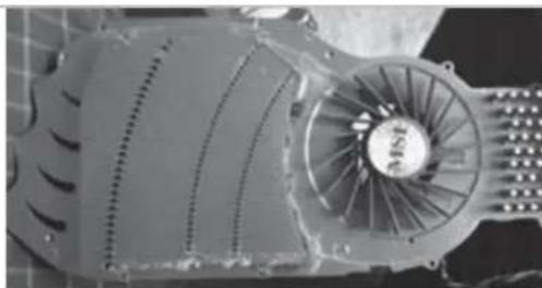
Close-up of a heat exchanger or cooling unit with multiple cooling fins and cooling tower (no visible text or symbols)ENGLISH
Q: If I have a tower-style CPU cooler, is it possible to run it without CPU fan installed?
A: It's possible but for best balance of cooling and quietness, installing a fan directly on the CPU cooler is usually more effective than installing exhaust fan on rear of the case.
DEUTSCH
Q: Why isn't an exhaust fan included?
A: The MM01's airflow path has been optimized using positive pressure design to dissipate heat. The two front 180mm fan will provide equal airflow for both CPU and graphic card area. From our test results, a rear exhaust fan creates an imbalanced airflow that lowers the CPU temperature slightly at the cost of greater cooling performance loss for the graphics card area. Even without an exhaust fan installed the hot air will still exit naturally from the rear. We have also found out through testing that installing a fan directly onto the CPU cooler results in overall quieter case compared to having a fan mounted in the rear exhaust fan slot due the latter's more exposed location and turbulence against the fan grille. So with all things considered, an exhaust fan is unnecessary with this case's design, but the rear fan mount is still included for convenient placement of all-in-one liquid cooling solution.
DEUTSCH
Q: Can I remove and clean the front fan filter while the computer is turned on?
A: To reduce the chance of foreign objects touching and damaging the spinning fans while the system is on, we recommend only removing and cleaning the filter when the system is off.
DEUTSCH
Q: When I turn on the computer, why doesn't the front 180mm spin?
A: If your fan is connected to the motherboard, we suggest you to turn off temperature control function in the BIOS. If you want to use temperature control function on your motherboard, we recommend you to set the MM01's physical fan speed switch to high for a lower starting voltage and a wider range of control. If the fans still do not spin, please contact reseller or SilverStone to arrange for replacement.
DEUTSCH
Q: I want to install customized liquid cooling system, do you have any recommendation?
A: Customized liquid cooling systems do not have a definite installation procedure. Typical chassis will not have provision for this. DIY users must make provisions themselves. If you want to install a 3 x 120mm radiator, we recommend Magicool Dual 180 Radiator instead. Although both types of radiators have the same length, the dual 180mm radiator has approximately 50% larger surface area for much higher performance potential.
DEUTSCH
Q: Why can't the fans spin up to their top speed of 2000rpm in the MM01?
A: Usually high resistance introduced by HEPA filter (compared to ordinary computer filters) can reduce the top speed of AP182 by 200rpm. This same effect will apply to any other fan installed in the MM01.
DEUTSCH
This product has a limited 1 year warranty in North America and Australia.
For information on warranty periods in other regions, please contact your reseller or SilverStone authorized distributor.
Warranty terms & conditions
- Product component defects or damages resulted from defective production is covered under warranty.
Defects or damages with the following conditions will be fixed or replaced under SilverStone Technology's jurisdiction.
a) Usage in accordance with instructions provided in this manual, with no misuse, overuse, or other inappropriate actions.
b) Damage not caused by natural disaster (thunder, fire, earthquake, flood, salt, wind, insect, animals, etc...)
c) Product is not disassembled, modified, or fixed. Components not disassembled or replaced.
d) Warranty mark/stickers are not removed or broken.
Loss or damages resulted from conditions other than ones listed above are not covered under warranty. - Under warranty, SilverStone Technology's maximum liability is limited to the current market value for the product (depreciated value, excluding shipping, handling, and other fees). SilverStone Technology is not responsible for other damages or loss associated with the use of product.
- Under warranty, SilverStone Technology is obligated to repair or replace its defective products. Under no circumstances will SilverStone Technology be liable for damages in connection with the sale, purchase, or use including but not limited to loss of data, loss of business, loss of profits, loss of use of the product or incidental or consequential damage whether or not foreseeable and whether or not based on breach of warranty, contract or negligence, even if SilverStone Technology has been advised of the possibility of such damages.
- Warranty covers only the original purchaser through authorized SilverStone distributors and resellers and is not transferable to a second hand purchaser.
- You must provide sales receipt or invoice with clear indication of purchase date to determine warranty eligibility.
- If a problem develops during the warranty period, please contact your retailer/reseller/SilverStone authorized distributors or SilverStone http://www.silverstonetek.com.
Please note that: (i) You must provide proof of original purchase of the product by a dated itemized receipt; (ii) You shall bear the cost of shipping (or otherwise transporting) the product to SilverStone authorized distributors. SilverStone authorized distributors will bear the cost of shipping (or otherwise transporting) the product back to you after completing the warranty service; (iii) Before you send the product, you must be issued a Return Merchandise Authorization ("RMA") number from SilverStone. Updated warranty information will be posted on SilverStone's official website. Please visit http://www.silverstonetek.com for the latest updates.
Additional info & contacts
For North America (usasupport@silverstonetek.com)
SilverStone Technology in North America may repair or replace defective product with refurbished product that is not new but has been functionally tested. Replacement product will be warranted for remainder of the warranty period or thirty days, whichever is longer. All products should be sent back to the place of purchase if it is within 30 days of purchase, after 30 days, customers need to initiate RMA procedure with SilverStone Technology in USA by first downloading the "USA RMA form for end-users" form from the below link and follow its instructions.
http://silverstonetek.com/contactus.php
For Australia only (support@silverstonetek.com)
Our goods come with guarantees that cannot be excluded under the Australian Consumer Law.
You are entitled to a replacement or refund for a major failure and for compensation for any other reasonably foreseeable loss or damage.
You are also entitled to have the goods repaired or replaced if the goods fail to be of acceptable quality and the failure does not amount to a major failure.
Please refer to above "Warranty terms & conditions" for further warranty details.
SilverStone Technology Co., Ltd. 12F No. 168 Jiankang Rd., Zhonghe Dist., New Taipei City 235 Taiwan R.O.C. + 886-2-8228-1238 (standard international call charges apply)
For China (support@silverstonetek.com.cn)
For Europe (support.eu@silverstonetek.de)
For all other regions (support@silverstonetek.com)
To be valid, this sheet must be filled out by your salesperson at the time of purchase.
Store :
Purchaser :
Purchase date :
Model No. :
Serial No.:
SilverStone Technology Co., Ltd.
www.silverstonetek.com
support@silverstonetek.com
NO: G11222061

- Installation and system optimization guide:
- - Introduction
- ENGLISH
- DEUTSCH
- РУССКИЙ
- ESPAÑOL
- Connector definition
- Front Panel Connector installation
- Front I/O connector guide
- Component Size Limitations
- CPU cooler height limitation
- Power supply and optical drive limitation
- A: Length limitation
- Graphics card/expansion card length limitation
- Motherboard size limitation
- CPU And Graphic Gard Supporter
- (1): CPU Cooler Supporter
- CPU And Graphic Card Supporter
- (2): Graphic card supporter
- 繁體中文
- Mammoth Series MM01
- Optimal Thermal Performance Layout
- Fan Speed Adjustment
- Upgrade And Maintenance
- Fan filter removal guide
- 簡体中文
- Bottom hard drive removal guide
- Warranty terms & conditions
- Additional info & contacts
Brand : SILVERSTONE
Model : Mammoth MM01
Category : Desktop Computer