CM523 - Fan FAR - Free user manual and instructions
Find the device manual for free CM523 FAR in PDF.

User questions about CM523 FAR
0 question about this device. Answer the ones you know or ask your own.
Ask a new question about this device
Download the instructions for your Fan in PDF format for free! Find your manual CM523 - FAR and take your electronic device back in hand. On this page are published all the documents necessary for the use of your device. CM523 by FAR.
USER MANUAL CM523 FAR
natural_image
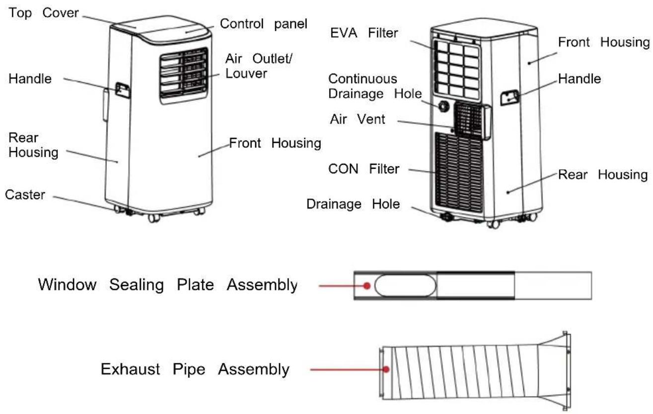
White industrial air conditioner unit with control panel and buttons (no visible text or symbols)CM5-23
MANUEL D'INSTRUCTIONS
natural_image
Three black-and-white line drawings: open book, open book with 'i' symbol, and open book with a key (no text or symbols)natural_image
Diagram showing a mechanical component transforming into a disassembled part (no text or symbols present)natural_image
Technical line drawing showing two views of a mechanical component with an arrow indicating direction (no text or symbols)- Assemblez la barre coulissante.
natural_image
Simple line drawing of a rectangular object with horizontal lines and an arrow pointing to it (no text or symbols)natural_image
Technical line drawing of two mechanical components with no visible text or symbolsnatural_image
Diagram of a window with two downward arrows and an arrow inside, no text or symbols present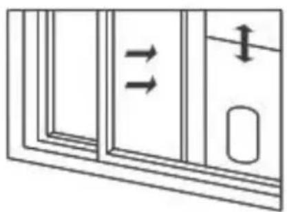
natural_image
Diagram of a window with double arrows indicating direction, no text or symbols presentFig. 2 Fig.3
natural_image
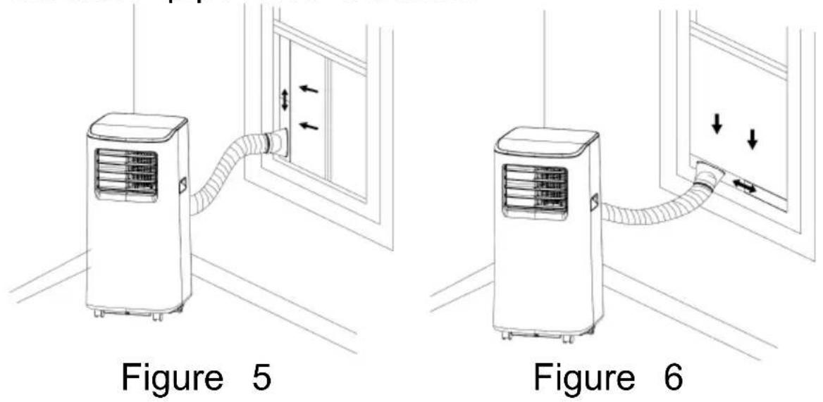
Line drawing of a small air conditioner unit connected to a wall-mounted door, showing airflow direction (no text or symbols)Fig. 5
natural_image
Line drawing of an air conditioner connected to a wall-mounted panel with directional arrows (no text or symbols)Fig. 6
Avis important :
natural_image
Line drawing of a portable air conditioner unit with cooling fins and ventilation slots (no text or symbols)Remarques :
natural_image
Line drawing of a large industrial air conditioner unit with a cylindrical base and tubing (no text or symbols)Entretien
natural_image
Line drawing of a portable air purifier with a grid panel and fan, shown in two views: one with a circular inset showing a grid component (no text or symbols)Unité de stockage
https://sav-client.conforama.fr

09 69 32 05 05
Thank you for choosing FAR quality. This product has been developed by our team of professional and according to European regulations in force. In order get the most out of your new appliance, we recommend that you read this instruction manual carefully and keep it for future reference.
Table of contents
Safety warnings......GB-2
Features and Components ....GB-19
Control Setting......GB-20
Protection function......GB-23
Installation and adjustment......GB-24
Drainage Instructions......GB-28
Maintenance......GB-30
Unit storage......GB-31
Troubleshooting......GB-32
Technical specifications......GB-34
Customer service....GB-36
Disposal of your old appliance......GB-37

THIS PRODUCT IS FOR HOUSEHOL USE ON LY! PLEASE READ CAREFULLY THIS MANUEL BEFORE YOUR FIRST USE AND SAVE IT FUTURE REFERENCE.
Safety warnings
1. Information on servicing
1) Checks to the area Prior to beginning work on systems containing flammable refrigerants, safety checks are necessary to ensure that the risk of ignition is minimised. For repair to the refrigerating system, the following precautions shall be complied with prior to conducting work on the system.
2) Work procedure
Work shall be undertaken under a controlled procedure so as to minimize the risk of a flammable gas or vapour being present while the work is being performed.
3) General work area
All maintenance staff and others working in the local area shall be instructed on the nature of work being carried out. Work in confined spaces shall be avoided. The area around the workspace shall be sectioned off. Ensure that the conditions within the area have been made safe by control of flammable material.
4) Checking for presence of refrigerant
The area shall be checked with an appropriate refrigerant detector prior to and during work, to ensure the technician is aware of potentially toxic or flammable atmospheres. Ensure that the leak detection equipment being used is suitable for use with all applicable refrigerants, i.e. non-sparking, adequately sealed or intrinsically safe.
5) Presence of fire extinguisher
If any hot work is to be conducted on the refrigeration equipment or any associated parts, appropriate fire extinguishing equipment shall be available to hand.
Have a dry powder or _2 fire extinguisher adjacent to the charging area.
6) No ignition sources
No person carrying out work in relation to a refrigerating system which involves exposing any pipe work shall use any sources of ignition in such manner it may lead to the risk of fire or explosion possible ignition sources, including cigarette smoking, should be kept sufficiently far away from the site of installation, repairing, removing and disposal, during which refrigerant can possibly be released to the surrounding space. Prior to work taking place, the area around the equipment is to surveyed to make sure that there are no flammable hazards or ignition risks.
"No Smoking" signs shall be displayed.
7) Ventilated area
Ensure that the area is in the open or that it is adequately ventilated before breaking into the
system or conducting any hot work. A degree of ventilation shall continue during the period that the work is carried out. The ventilation should safely disperse any released refrigerant and preferably expel it externally into the atmosphere.
8) Checks to the refrigeration equipment
Where electrical components are being changed, they
shall be fit for the purpose and to the correct specification. At all times the manufacturer's maintenance and service guidelines shall be followed. If in doubt consult the manufacturer's technical department for assistance. The following checks shall be applied to installations using flammable refrigerants:
- the actual refrigerant charge is in accordance with the room size within which the refrigerant containing parts are installed;
- The ventilation machinery and outlets are operating adequately and are not obstructed;
- If an indirect refrigerating circuit is being used, the secondary circuit shall be checked for the presence of refrigerant;
- Marking to the equipment continues to be visible and legible. Markings and signs that are illegible shall be corrected;
- Refrigeration pipe or components are installed in a position where they are unlikely to be exposed to any substance which may corrode refrigerant containing components, unless the components are constructed of materials which are inherently
resistant to being corroded or are suitably protected against being so corroded.
9) Checks to electrical devices
Repair and maintenance to electrical components shall include initial safety checks and component inspection procedures. If a fault exists that could compromise safety, then no electrical supply shall be connected to the circuit until it is satisfactorily dealt with. If the fault cannot be corrected immediately but it is necessary to continue operation an adequate temporary solution shall be used. This shall be reported to the owner of the equipment so all parties are advised.
Initial safety checks shall include:
- That capacitors are discharged: this shall be done in a safe manner to avoid possibility of sparking;
- That there no live electrical components and wirir are exposed while charging, recovering or purging the system;
- That there is continuity of earth bonding.
- Repairs to sealed components
1) During repairs to sealed components, all electrical supplies shall be disconnected from the equipment being worked upon prior to any removal of sealed covers, etc. If it is absolutely necessary to have an electrical supply to equipment during servicing, then a permanently operating form of leak detection shall be located at the most critical point to warn of a potentially hazardous situation.
2) Particular attention shall be paid to the following to ensure that by working on electrical components,
the casing is not altered in such a way that the I of protection is affected. This shall include damage to cables, excessive number of connections, terminals not made to original specification, damage to seals, incorrect fitting of glands, etc.
Ensure that the apparatus is mounted securely.
Ensure that seals or sealing materials have not degraded to the point that they no longer serve the purpose of preventing the ingress of flammable atmospheres.
Replacement parts shall be in accordance with the manufacturer's specifications.
- Repair to intrinsically safe components
Do not apply any permanent inductive or capacitance loads to the circuit without ensuring that this will not exceed the permissible voltage and current permitted for the equipment in use.
Intrinsically safe components are the only types that can be worked on while live in the presence of a flammable atmosphere.
The test apparatus shall be at the correct rating.
Replace components only with parts specified by the manufacturer. Other parts may result in the ignition of refrigerant in the atmosphere from a leak.
NOTE The use of silicon sealant can inhibit the effectiveness of some types of leak detection equipment. Intrinsically safe components do not have to be isolated prior to working on them.
- Cabling
Check that cabling will not be subject to wear, corrosion, excessive pressure, vibration, sharp edges
or any other adverse environmental effects. The check shall also take into account the effects of aging or continual vibration from sources such as compressors or fans.
5. Detection of flammable refrigerants
Under no circumstances shall potential sources of ignition be used in the searching for or detection of refrigerant leaks. A halide torch (or any other detector using a naked flame) shall not be used.
6. Leak detection methods
The following leak detection methods are deemed acceptable for systems containing flammable refrigerants. Electronic leak detectors may be used to detect refrigerant leaks but, in the case of flammable refrigerants, the sensitivity may not be adequate, or may need re-calibration. (Detection equipment shall be calibrated in a refrigerant-free area.) Ensure that the detector is not a potential source of ignition and suitable for the refrigerant used. Leak detection equipment shall be set at a percentage of the LFL the refrigerant and shall be calibrated to the refrigerant employed, and the appropriate percentage of gas (25 % maximum) is confirmed.
Leak detection fluids are also suitable for use with most refrigerants but the use of detergents containing chlorine shall be avoided as the chlorine may react with the refrigerant and corrode the copper pipe-work NOTE Examples of leak detection fluids are
- bubble method,
- fluorescent method agents.
If a leak is suspected, all naked flames shall be removed/extinguished.
If a leakage of refrigerant is found which requires brazing, all of the refrigerant shall be recovered from the system, or isolated (by means of shut off valves) a part of the system remote from the leak. Removal refrigerant shall be according to Clause 7.
7. Removal and evacuation
When breaking into the refrigerant circuit to make repairs - or for any other purpose - conventional procedures shall be used. However, for flammable refrigerants it is important that best practice is followed since flammability is a consideration. The following procedure shall be adhered to:
- remove refrigerant;
- purge the circuit with inert gas (optional for A2L);
- evacuate (optional for A2L);
- purge with inert gas (optional for A2L);
- open the circuit by cutting or brazing.
The refrigerant charge shall be recovered into the correct recovery cylinders. For appliances containing flammable refrigerants other than A2L refrigerants, the system shall be purged with oxygen-free nitrogen to render the appliance safe for flammable refrigerants.
This process may need to be repeated several times.
Compressed air or oxygen shall not be used for purging refrigerant systems.
For appliances containing flammable refrigerants, other than A2L refrigerants, refrigerant purging shall be achieved by breaking the vacuum in the system with oxygen-free nitrogen and continuing to fill until
the working pressure is achieved, then venting to atmosphere, and finally pulling down to a vacuum. This process shall be repeated no refrigerant is within the system. When the final oxygen-free nitrogen charge is used, the system shall be vented down to atmospheric pressure to enable work to take place. This operation is absolutely vital if brazing operations on the pipe-work are to take place.
Ensure that the outlet for the vacuum pump is not close to any ignition sources and there is ventilation available.
8. Charging procedures
In addition to conventional charging procedures, the following requirements shall be followed.
- Ensure that contamination of different refrigerants does not occur when using charging equipment.
Hoses or lines shall be as short as possible to minimize the amount of refrigerant contained in them.
Cylinders shall be kept in an appropriate position according to the instructions.
Ensure that the refrigerating system is earthed prior to charging the system with refrigerant.
Label the system when charging is complete (if not already). Extreme care shall be taken not to overfill the refrigerating system.
Prior to recharging the system, it shall be pressure-tested with the appropriate purging gas. The system shall be leak-tested on completion of charging but prior to commissioning. A follow up leak test shall be carried out prior to leaving the site.
9. Decommissioning
Before carrying out this procedure, it is essential that the technician is completely familiar with the equipment and all its detail. It is recommended good practice that all refrigerants are recovered safely. Price to the task being carried out, an oil and refrigerant sample shall be taken in case analysis is required prior to re-use of reclaimed refrigerant. It is essential that electrical power is available before the task is commenced.
a) Become familiar with the equipment and its operation.
b) Isolate system electrically.
c) Before attempting the procedure ensure that:
- Mechanical handling equipment is available, if required, for handling refrigerant cylinders;
- All personal protective equipment is available and being
used correctly;
- The recovery process is supervised at all times by a competent person;
- Recovery equipment and cylinders conform to the appropriate standards.
d) Pump down refrigerant system, if possible.
e) If a vacuum is not possible, make a manifold so refrigerant can be removed from various parts of the system.
f) Make sure that cylinder is situated on the scales before recovery takes place.
f) Make sure that cylinder is situated on the scales before recovery takes place.
g) Start the recovery machine and operate in accordance with instructions.
h) Do not overfill cylinders. (No more than 80 % volume liquid charge).
i) Do not exceed the maximum working pressure of the cylinder, even temporarily.
j) When the cylinders have been filled correctly and the process completed, make sure that the cylinders and the equipment are removed from site promptly and all isolation valves on the equipment are closed off.
k) Recovered refrigerant shall not be charged into another refrigeration system unless it has been cleaned and checked.
10. Labeling
Equipment shall be labelled stating that it has been decommissioned and emptied of refrigerant. The label shall be dated and signed. For appliances containing flammable refrigerants, ensure that there are labels on the equipment stating the equipment contains flammable refrigerant.
11. Recovery
When removing refrigerant from a system, either for servicing or decommissioning, it is recommended good practice that all refrigerants are removed safely.
When transferring refrigerant into cylinders, ensure that only appropriate refrigerant recovery cylinders are employed. Ensure that the correct number of cylinders for holding the total system charge are available. All cylinders to be used are designated for the recovered refrigerant and labelled for that refrigerant (i.e. special cylinders for the recovery of refrigerant). Cylinders shall be complete with pressure relief valve and
associated shut-off valves in good working order. Empty recovery cylinders are evacuated and, if possible, cooled before recovery occurs.
The recovery equipment shall be in good working order with a set of instructions concerning the equipment that is at hand and shall be suitable for recovery of all appropriate refrigerants including, when applicable, flammable refrigerants. In addition, a set of calibrated weighing scales shall be available and in good working order. Hoses shall be complete with leak-free disconnect couplings and in good condition. Before using the recovery machine, check that it is satisfactory working order, has been properly maintained and that any associated electrical components are sealed to prevent ignition in the eve of a refrigerant release. Consult manufacturer if in doubt.
The recovered refrigerant shall be returned to the refrigerant supplier in the correct recovery cylinder, and the relevant Waste Transfer Note arranged. Do not mix refrigerants in recovery units and especially not in cylinders. If compressors or compressor oils are to be removed, ensure that they have been evacuated to an acceptable level to make certain that flammable refrigerant does not remain within the lubricant. The evacuation process shall be carried out prior to returning the compressor to the suppliers. Only electric heating to the compressor body shall be employed to accelerate this process. When oil is drained from a system, it shall be carried out safely
- Do not use means to accelerate the defrosting process or to clean, other than those recommended by the manufacturer.
- The appliance shall be stored in a room without continuously operating ignition sources (for example: open flames, an operating gas appliance or an operating electric heater.
- Do not pierce or burn.
- Be aware that refrigerants may not contain an odour.
- Appliance shall be installed, operated and stored in a room with a floor area larger than 5 m
- Keep any required ventilation openings clear of obstruction.
- a warning that the appliance shall be stored in well-ventilated area where the room size corresponds to the room area as specified for operation;
- a warning that the appliance shall be stored in room without continuously operating open flames (for example an operating gas appliance) and ignition sources (for example an operating electric heater).
- Any person who is involved with working on or breaking into a refrigerant circuit should hold a current valid certificate from an industry-accredited assessment authority, which authorises their competence to handle refrigerants safely in accordance with an industry recognised assessment specification.
- Servicing shall only be performed as recommended by the equipment manufacturer. Maintenance and repair requiring the assistance of
other skilled personnel shall be carried out under the supervision of the person competent in the use of flammable refrigerants.
- All working procedure that affects safety means shall only be carried by competent persons.
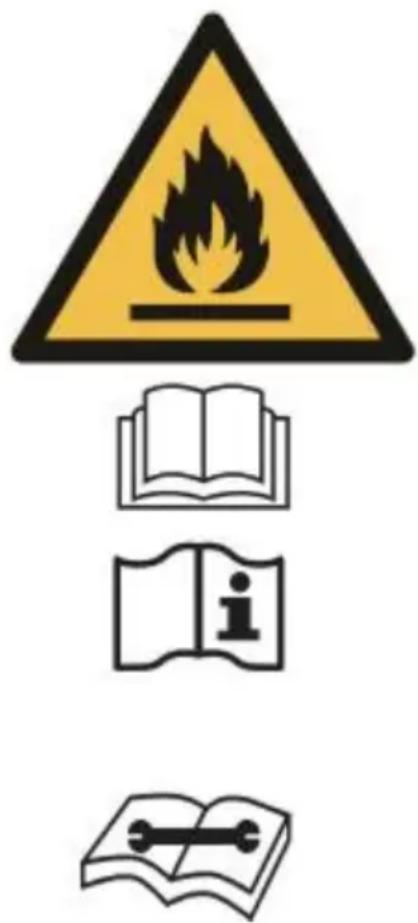
Appliance is filled with flammable gas R290. Caution, risk of fire R290
Before using the appliance, read the manual.
Before installing the appliance read the installation manual.
Any repairs you need, contact the nearest authorized Servi Centre and strictly follow manufacturer's instruction only.
- The air conditioning is only suitable for indoor u and is not suitable for other applications
-
Follow local grid interconnection rules while installing the air conditioning and ensure that it is properly grounded. If you have any question on electrical installation, follow the instructions of the manufacturer, and if necessary ask a professional electrician to install it.
-
Place the machine in a flat and dry place and a distance of above 50cm between the machine and the surrounding objects or walls.
- After the air conditioning is installed, ensure that the power plug is intact and firmly plugged into the power outlet, and place the power cord orderly to prevent someone from being tripped or pulling out the plug
- Do not put any object into the air inlet and out the air conditioning, keep the air inlet and outlet free from obstructions.
- when drainage pipes are installed, ensure that the drainage pipes are properly connected, and are not distorted or bended.
- while adjusting the upper and lower wind-guide strips of the air outlet, pluck it with hands gently to avoid damaging wind-guide strips.
- when moving the machine, make sure that it is an upright position.
- The machine should stay away from gasoline flammable gas, stoves and other heat sources.
- Don't disassemble, overhaul and modify the machine arbitrarily therewise it will cause a machine malfunction or even bring harm to persons and properties. To avoid danger, if a machine failure occurs, ask the manufacturer or professionals to repair it.
- Do not install and use the air conditioning in the bathroom or other humid environments.
-
Do not pull the plug to turn off the machine.
-
Do not place cups or other objects on the body prevent water or other liquids from spilling into the a conditioning.
- Do not use insecticide sprays or other flammable substances near the air conditioning.
- Do not wipe or wash the air conditioning with chemical solvents such as gasoline and alcohol. When you need to clean the air conditioning You must disconnect the power supply and clean it with a half-wet soft cloth. If the machine is really dirty scrub with mild detergent.
- This appliance can be used by children aged from 8 years and above and persons with reduced physical sensory or mental capabilities or lack of experience and knowledge if they have been given supervision instruction concerning use of the appliance in a safe way and understand the hazards involved. Children shall not play with the appliance. Cleaning and user maintenance shall not be made by children without supervision.
- If the supply cord is damaged, it must be repla by the manufacturer, its service agent or similarly qualified persons in order to avoid a hazard.
- Do not operate your air conditioner in a wet roof such as a bathroom or laundry room.
- The appliance shall be stored so as to prevent mechanical damage from occurring.
- This appliance is intended to be used in house and similar applications such as:
-
staff kitchen areas in shops, offices and other working environments;
-
farm houses;
- by clients in hotels, motels and other residential ty environments;
- bed and breakfast type environments.
- Internal fuse rated voltage 250VAC, current 3.15A
- An unventilated area where an appliance that us flammable refrigerants is installed must be
constructed in such a way that in the event of a refrigerant leak, it will not stagnate and create a risk fire or explosion. - WARNING: The appliance must be stored in a room that does not contain any open flames that are constantly operating (e.g. a gas appliance) or sources of ignition (e.g. an electric heater in operation).
- Qualification of workers
The manual shall contain specific information about the required qualification of the working personnel for maintenance, service and repair operations. Every working procedure that affects safety means shall only be carried out by competent persons.
Examples for such working procedures are: - breaking into the refrigerating circuit;
- opening of sealed components;
- opening of ventilated enclosures.
servicing shall be performed only as recommended by the manufacturer.
Transportation, marking and storage for units
- Transport of equipment containing flammable refrigerants in compliance with the transport regulations
2 Mark signs of equipment use in compliance with local regulations
3. Disposal of equipment using flammable refrigerants in compliance with national regulations
4. Storage of equipment/appliances
The storage of equipment should be in accordance with the manufacturer's instructions.
5. Storage of packed (unsold) equipment storage package protection should be constructed. For example, mechanical damage to the equipment inside the package won 't cause a leak of the refrigerant charge. The maximum number of pieces of equipment permitted to be stored together will be determined by local regulations.
Safety information for remote control :
- The type of battery is 2x1.5V AAA; (not included)
- Push the battery cover to the bottom according to direction indicated by the arrow on the battery cover, insert or remove the two batteries according to the indication, and finally push the battery cover in the opposite direction of the direction indicated by the arrow on the battery cover;
- Non-rechargeable batteries are not to be recharged;
- Rechargeable batteries are to be removed from the appliance before being charged;
- Different types of batteries or new and used battery are not to be mixed;
- Batteries are to be inserted with the correct polarit
- Exhausted batteries are to be removed from the appliance and safely disposed of;
- If the appliance is to be stored unused for a long period, the batteries should be removed;
- The supply terminals are not to be short-circuited.
Features and Components
Features
Brand new appearance, compact structure, smooth line, simple and generous shape.
Functions of refrigeration, dehumidification, air supply and continuous drainage.
Outdoor interface is set high to facility assembly and keep the smooth flow of the heat pipe.
LED displays the control panel, beautiful and fashionable, with high-quality remote control. It adopts a user friendly remote control design.
Air filtration capability.
Timing switch function.
Protection function of automatically restarting the compressor after three minutes, a variety of other protection functions.
The max operation temperature for the air conditioner cooling:35/24 °C; Temperature setting range: 7-35 °C.
Components
Control Setting
Control panel operation instructions operation interface:
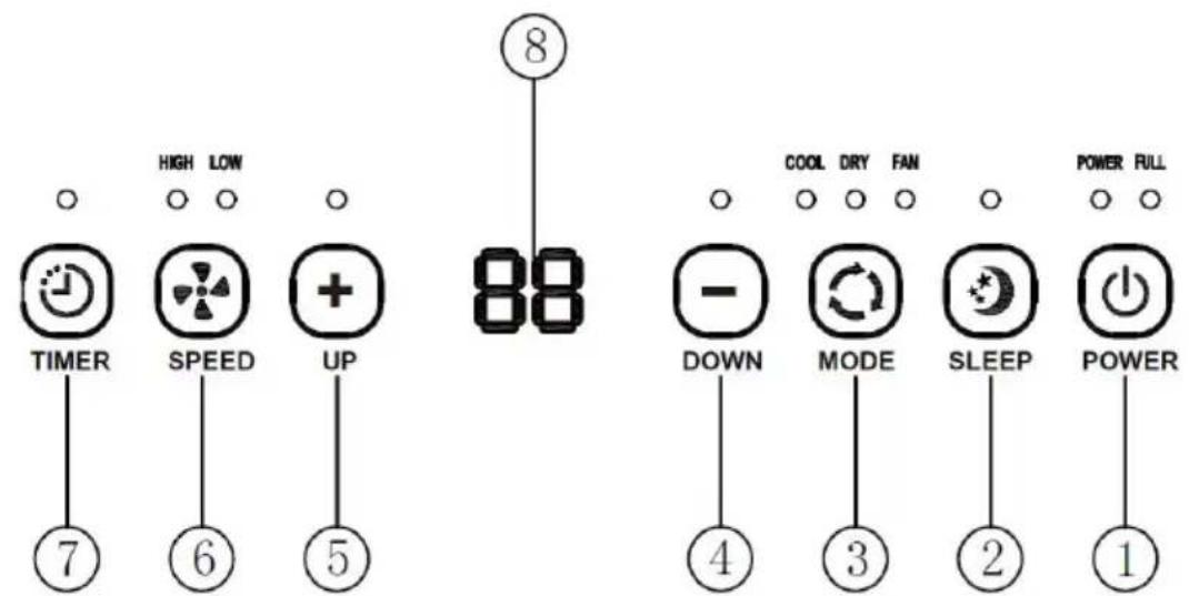
- Power Key
- Sleep Key
- Mode Selection Key
- Down Key
5.Up Key
6.Speed Key - Timer key
- Display Key
When the machine is powered on for the first time, buzzer will play power sound, and then the machine will get into standby status.
Power key: Press the key to turn on and turn off machine. In the case of power on, press the key to turn off the machine; in the case of power off, press the key to turn on the machine.
Cooling key: Press this button to cooling of the machine.
Tank Full Indicator Light: When this light comes on it means that the machine will stop working when the water is full and the water needs to be drained away. Timing key: In the case of power on, press the key close timer; in the case of power off, press the key open timing. Press the key, when the timing symbol flashes, press up and down key to select the required timing value. Timing values can be set in 1 - 24 h and the timing value is adjusted up or down by one hour.
Wind speed selection key: In cooling and fan mode press the key to select high, low wind speed operate. But limited by anti-cold conditions, under certain conditions, it may not run according to the set wind speed. In dehumidifying mode, pressing the key is
invalid, and the fan will forcibly choose low wind speed operation.
Sleep Mode: In the cooling Mode, press the SLEEP key to turn on the sleep mode, then the unit will wo on Energy-saving and quiet type.
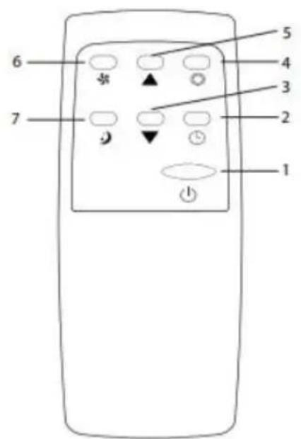
Operation instructions of remote control The remote control Panel is as follows:
Instructions of key operation of the high-quality remot control are as follows:
- Power: press the key to turn on or turn off the machine.
- Timer: press the key to set timing
- Down: press ▼ the key to reduce temperature at timing set value.
- Mode: press the key to switch between cooling, dehumidifying, fan mode.
- Up: press ▲ the key to increase temperature and timing set value.
- Fan: press the key to select high, low wind speed.
- Sleep Mode: press the key to turn on the sleep Mode.
Protection function
Frost Protection Function:
In cooling, dehumidifying or economic power saving mode, if the temperature of the exhaust pipe is too the machine will automatically enter protection status; if the temperature of the exhaust pipe rises to a certain temperature, it can automatically revert to normal operation.
Overflow Protection Function:
When water in the water pan exceeds the warning level, the machine will automatically sound an alarm, and the "FULL" indicator light will flash. At this point you need to move the drainage pipe connecting the machine or the water outlet to sewer or other drainage area to empty the water (details see Drainage Instructions at the end of this chapter). When the water is emptied, the machine will automatically return to the original state.
Protection Function of the Compressor
To increase the service life of the compressor, it has 3-minute delay booting protection function after the compressor is turned off.
Installation and adjustment
Installation
Warning: before using the mobile air conditioning, keep it upright for at least two hours. The air conditioning can be easily moved in the room. In the moving process, ensure that the air conditioning is in the upright position and the air conditioning should be placed on a flat surface. Do not install and use the conditioning in the bathroom or other humid environments.
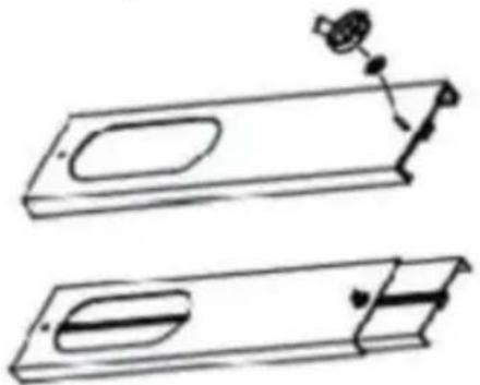
1.1 Install the heat pipe assembly ( as shown in Fi
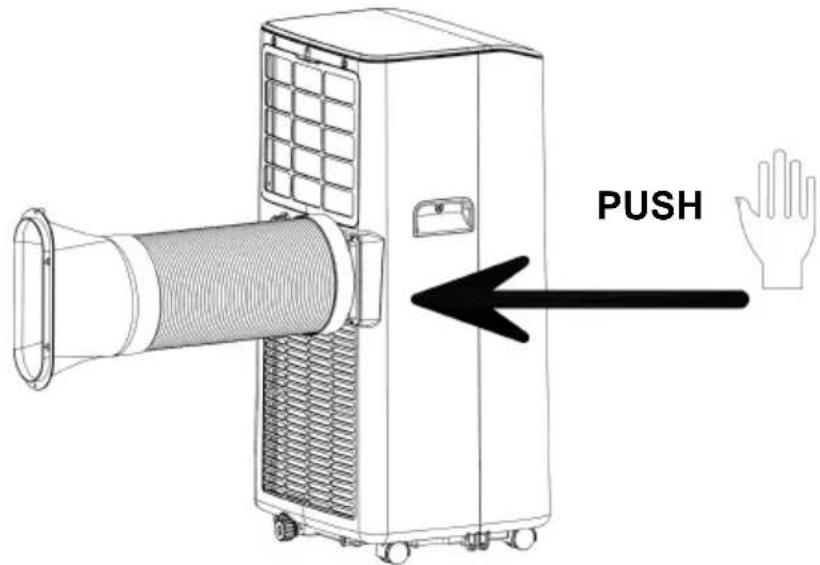
Figure 1
1) Take out the outer connector assembly and the exhaust pipe assembly, and remove the plastic bags;
2) Insert the heat pipe assembly (the end of the exhaust joint) into the back panel vent slot (push to
the left) and complete the assembly ( as shown in figure 1 ).
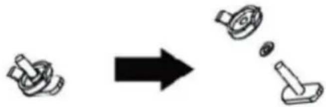
1.2 Installation of window sealing plate components How to fix the screw of adjustable slide bar
- Disassemble the screw, washer and nut.
natural_image
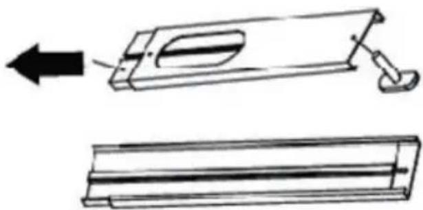
Diagram showing a mechanical component transforming into a disassembled part (no text or symbols present)- Separate 2 pieces of the slide bar and insert the screw into the hole.
natural_image
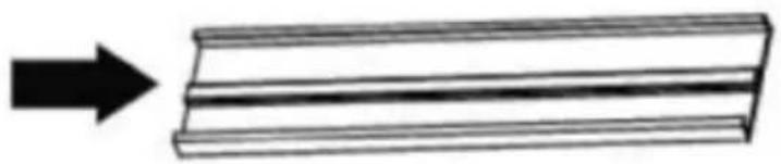
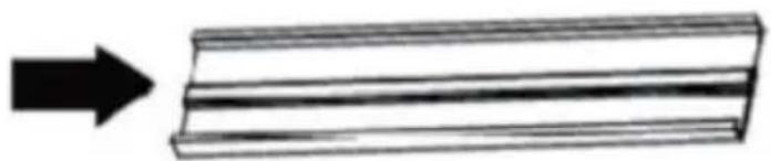
Technical line drawing showing two views of a mechanical component with an arrow indicating direction (no text or symbols)- Assemble the slide bar.
natural_image
Simple line drawing of a rectangular object with an arrow pointing to it (no text or symbols)- Tighten the washer and nut.
natural_image
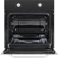
Two technical line drawings of a mechanical part with cutouts and mounting holes (no text or symbols)1) Half open the window and mount the window sealing plate assembly to the window (as shown in 2 and Fig. 3). components can be placed in horizon and vertical direction.
2) Pull various components of the window sealing plate assembly open, adjust their opening distance to bring both ends of the assembly into contact with the window frame, and fix various components of the assembly.
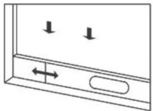
natural_image
Simple line drawing of a cabinet with two downward arrows and an arrow indicating left motion (no text or symbols)Figure 2
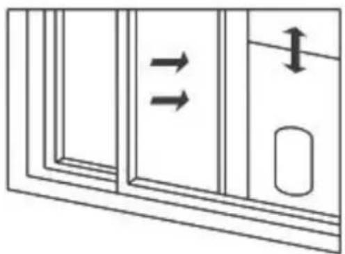
natural_image
Diagram of a door with two arrows indicating flow direction, no text or symbols presentFigure 3
1.3 Install the window sealing plate assembly Notes:
1) The flat end of the exhaust pipe joints must be snapped into place.
2) The pipe cannot be distorted nor has substantial turning (greater than 45). Keep the ventilation of exhaust pipe not blocked.
Install the body
Move the machine with installed heat pipe and fitting before the window, and the distance between the body and walls or other objects shall be least 50 c (as shown in Fig.4).
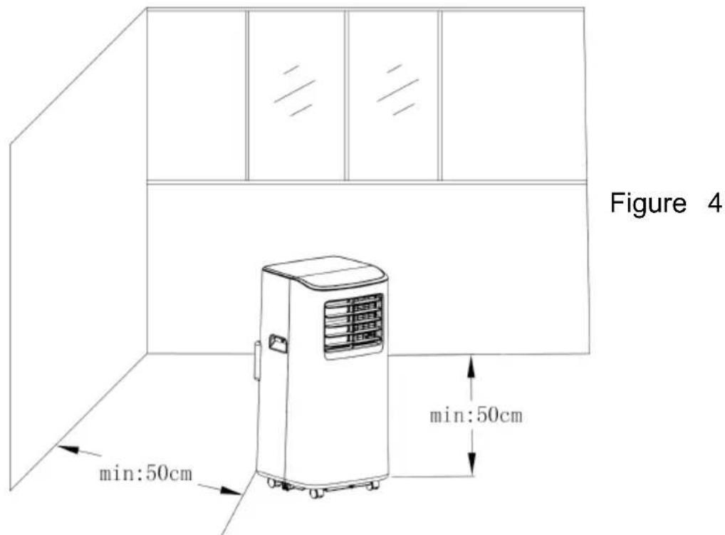
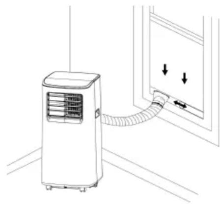
Elongate the exhaust pipe and snap the flat end of exhaust pipe joints into the hole of the window seal plate assembly (as shown in Fig.5 and Fig.6).
Notes:
1、The flat end of the exhaust pipe joints must be snapped into place.
2、The pipe cannot be distorted nor has substantial turning (greater than 45). Keep the ventilation of the exhaust pipe not blocked.
GB-27
Important Notice:
The length of the exhaust hose shall be 280\~1,500mm, and this length is based on the specifications of the air conditioning. Do not use extension tubes or replace it with other different hose or this may cause a malfunction.
Exhaust hose must be not blocked; otherwise it may cause overheating.
Drainage Instructions
This machine has two drainage methods: manual drainage and continuous drainage.
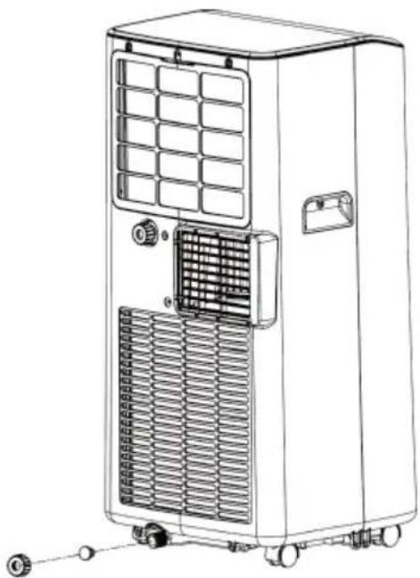
Manual drainage:
When the machine stops after the water is full, turn the machine power and unplug the power plug.
Notes: Please move the machine carefully, so as not spill the water in the water pan at the bottom of the body.
Place the water container below the side water outle behind the body.
Unscrew the drainage cover and unplug the water plug, the water will automatically flow into the water container.
natural_image
Line drawing of a portable air conditioner unit with ventilation grilles and control panel (no text or symbols)Notes:
Keep the drainage cover and the water plug properly. During drainage, the body can be tilted slightly backwards. If the water container cannot hold all the water, before the water container is full, stuff the water outlet with the water plug as soon as possible to prevent water from flowing to the floor or the carpet. When the water is discharged, stuff the water plug, and tighten the drainage cover.
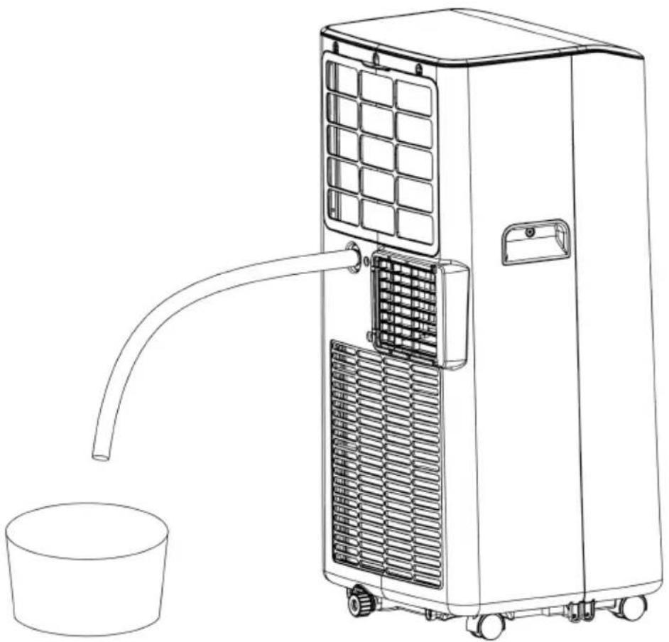
Continuous drainage (optional) (only applicable to dehumidifying mode), as shown in figure:
Unscrew the drainage cover, and unplug the water plug. Set the drainage pipe into the water outlet.
Connect the drainage pipe to the bucket.
natural_image
Line drawing of a large industrial air conditioner unit with a cylindrical base and pipe outlet (no text or symbols)Maintenance
Cleaning: Before cleaning and maintenance, turn off the machine and unplug the plug.
Clean the surface
Clean with surface of machine with a wet soft cloth. Don't use chemicals, such as benzene, alcohol, gasoline, etc; otherwise, the surface of the air conditioning will be damaged or even the whole machine will be damaged.
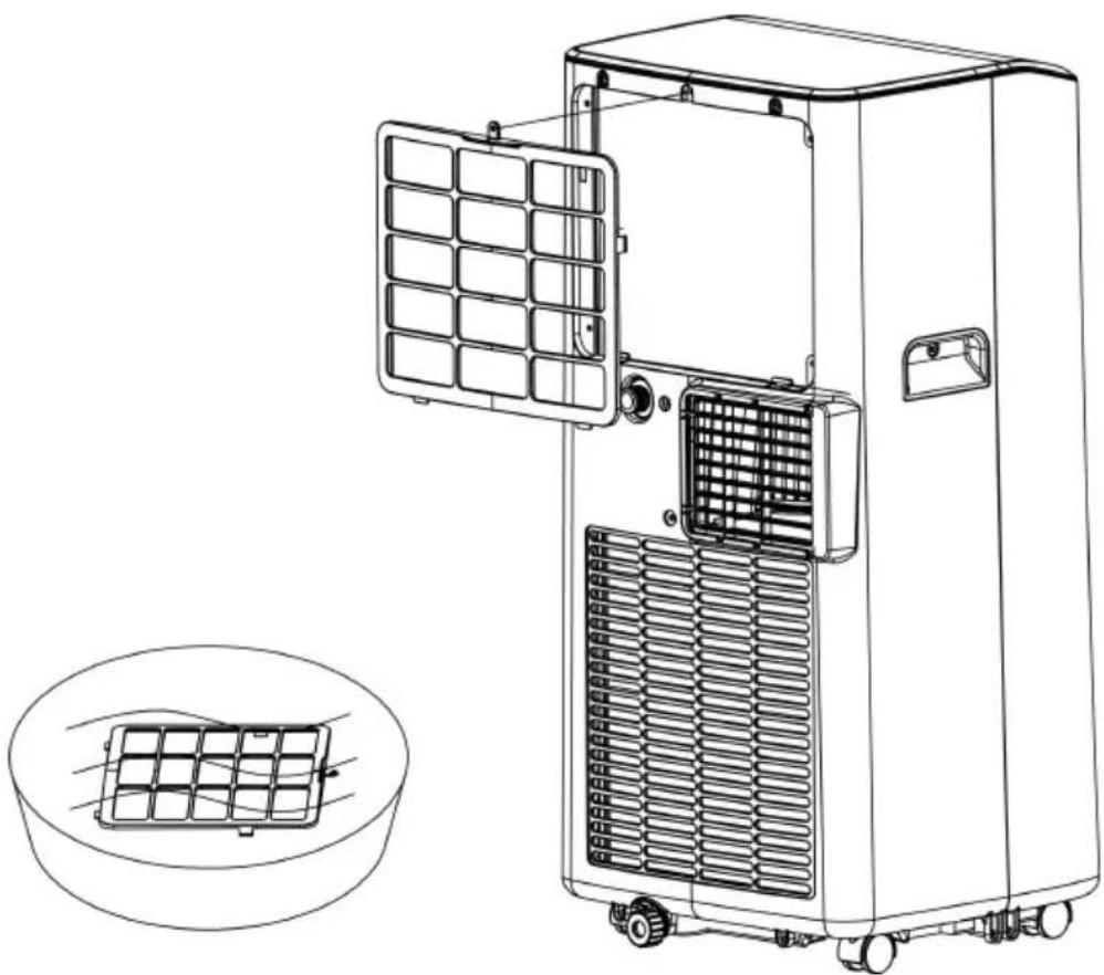
Clean the filter screen
If the filter screen is clogged with dust, and the effectiveness of the air conditioning is reduced, be sure to clean the filter screen once every two weeks
natural_image
Line drawing of a portable air conditioner unit with grid panel and fan, shown with an inset diagram of its internal structure (no text or symbols)Clean the upper filter screen frame
Unscrew one screw fixed by EVA filter net and back shell with screwdriver, and take out EVA filter net. Put the EVA filter screen into warm water with neutral detergent (about 40 °C/104°F) and dry it in the shade after rinsing clean.
Unit storage
Unscrew the drainage cover, unplug the water plug, and discharge the water in the water pan into other water containers or directly tilt the body to discharge the water into other containers.
Turn on the machine, adjust it to low-wind ventilation mode, and maintain this state until the drainage pipe becomes dry, so as to keep the inside of the body dry state and prevent it from mildewing.
Turn off the machine, unplug the power plug, and wrap the power cord around the wrapping post; insta the water plug and the drainage cover.
Remove the exhaust pipe and keep it properly.
Cover the air conditioning with a plastic bag. Put the air conditioning in a dry place, keep it out of the roof of children, and take dust control measures.
Remove batteries of the remote control and keep them properly.
Note: Ensure that the body is placed in a dry place and keep all machine components properly.
Troubleshooting
Do not repair or disassemble the air conditioning by yourself. Unqualified repair will lead to failure of the warranty card, and may cause damage to users or their properties.
| Problems | Reasons | Solutions |
| The air conditioning does not work. | There is no electricity. | Turn it on after connecting it to a sock with electricity. |
| The overflow indicator displays "FL". | Discharge the water inside. | |
| The ambient temperature is too low or too high.In cooling mode, the ro temperature is lower tha the set temperature; | Recommend to use the machine in at the temperature of 7-35 °C (44-95 °F).Change the set temperature. | |
| In dehumidification mode the ambient temperature is low. | The machine is placed a room with an ambier temperature of greater than 17 °C (62 °F). | |
| The cooling effect not good | There is direct sunlight. | Pull the Curtain. |
| Doors or windows are open; there area lot of people; or in cooling mode, there are other sources of heat. | Close doors and windows, and add new air conditioning. | |
| The filter screen is dirty | Clean or replace the fi screen. | |
| The air inlet or outlet i blocked. | Clear obstructions. | |
| Big Noise | The air conditioning is placed on a flat surface | Put the air conditioning on a flat and hard place(to reduce noise). |
| compressor does not work. | Overheat protection starts. | Wait for 3 minutes unt the temperature is lowered, and then resta the machine. |
| The remote control does not work. | The distance between the machine and the remote control is too far. | Let the remote control close to the air conditioning, and make sure that the remote control directly faces to the direction of the remote control receiver. |
| The remote control not aligned with the direction of the remote control receiver. | ||
| Batteries are dead. | Replace batteries. | |
| Displays 'E1' | The room temperature sensor is abnormal. | Check the room temperature sensor and related circuitry. |
| Displays 'E2' | The pipe temperature sensor is abnormal. | Check the pipe temperature sensor and related circuitry. |
Note: If problems not listed in the table occur or recommended solutions do not work, please contact the professional service organization.
Technical specifications
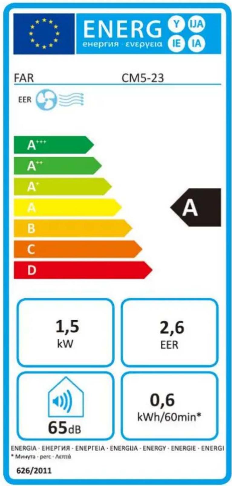
| Productfiche | |||
| Trade mark | FAR | ||
| model | CM5-23 | ||
| Energy efficiency class | A | ||
| Description | Symbol | Value | Unit |
| Rated capacity for cooling | P_rated for cooling | 1.5 | kW |
| Rated power input for cooling | P_EER | 0.575 | kW |
| Rated Energy efficiency ratio | EERd | 2.6 | - |
| Power consumption in thermostat-off mode | P_TO | - | W |
| Power consumption in standby mode | P_SB | 1 | W |
| Electricity consumption of single duct appliances | Q_SD | 0.6 | kWh/h |
| Energy consumption 0.6 kWh per 60 minutes, b on standard test results. Actual energy consump will depend on how the appliance is used and is located. | |||
| Sound power level | L_WA | 65 | dB(A) |
| Global warming potential | GWP | 3 | kgCO2eq. |
| Refrigerant leakage contributes to climate change Refrigerant with lower global warming potential ( would contribute less to global warming than a refrigerant with higher GWP, if leaked to the atmosphere. This appliance contains a refrigerant with a GWP equal to 3. This means that if 1 refrigerant fluid would be leaked to the atmosphere the impact on global warming would be 3 times than 1 kg of 2, Cover a period of 100 years. Ne to interfere with the refrigerant circuit yourself of disassemble the product yourself and always as professional.(Refrigerant: R290/100g) | |||
| Contact detail for obtaining more information | CONFORAMA FRANCE80 Boulevardu Mandinet LOGNES 77432 MARN LA VALLEE CEDEX 2 FRANCE | ||
bar
| Level | Energy Consumption (kWh/60min) | | :--- | :--- | | A | 1,5 | | B | 2,6 | | C | 0,6 | | D | 65 | ENERGIA · EHERΓΙΑ · ENEPΓΕΙΑ · ENERGIJA · ENERGY · ENERGIE · ENERGI * Минута · perc · Лептá 626/2011Customer service
We decline liability for any damage or accident derived from any use of this appliance which is not conformity with the instructions contained in this manual.
In accordance with Article L. 217 of the Consumer Code, your product benefits from a legal guarantee (conformity of 2 years.
If you have a problem with your product, before going to your Conforama store, please get in touchwith our aftersales services for electrical household appliances:
https://sav-client.conforama.fr

09 69 32 05 05
From Monday to Saturday, 08:30 to 19:00 Price of a local call
This instruction manual is also available on our website: www.conforama.fr
Disposal of your old appliance
European directive 2012/19/EU on Waste Electrical and Electronic Equipment (WEEE), requires that used household appliances are not thrown into the normal municipal waste stream. Used appliances must be collected separately in order to optimize the rate of recovery and recycling of materials that compose them, and to reduce the impact on human health and on the environment. The crossed bin symbol is affixed to all the products to remind you of the obligations of separated collection.