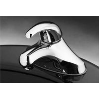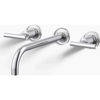
Bancroft K-T10592-4 - Faucet KOHLER - Free user manual and instructions
Find the device manual for free Bancroft K-T10592-4 KOHLER in PDF.


User questions about Bancroft K-T10592-4 KOHLER
0 question about this device. Answer the ones you know or ask your own.
Ask a new question about this device
Download the instructions for your Faucet in PDF format for free! Find your manual Bancroft K-T10592-4 - KOHLER and take your electronic device back in hand. On this page are published all the documents necessary for the use of your device. Bancroft K-T10592-4 by KOHLER.
USER MANUAL Bancroft K-T10592-4 KOHLER
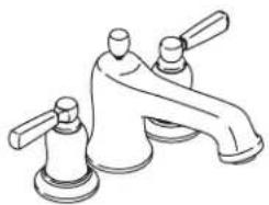
Bath- or Deck-Mount Faucet Trim
K-T10592
natural_image
Line drawing of a pair of bathroom fixtures (no text or symbols)M product numbers are for Mexico (i.e. K-12345M)
Thank You For Choosing Kohler Company
We appreciate your commitment to Kohler quality. Please take a few minutes to review this manual before you start installation. If you encounter any installation or performance problems, please don't hesitate to contact us. Our phone numbers and website are listed on the back cover. Thanks again for choosing Kohler Company.
Tools and Materials
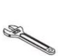
Adjustable Wrench
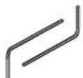
Hex Wrench 5/32"

Plumbers
Putty
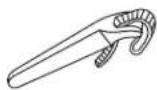
Strap Wrench
Plus:
• Rags
Before You Begin
□ Please read all instructions before you begin.
□ Observe all local plumbing and building codes.
☐ Before installation, unpack the new faucet trim and inspect it for damage. Return it to the carton until installation.
☐ Install the required valves, K-438-K-NA or K-P438-K-NA, prior to installing the product. Refer to the installation instructions packed with the valves.
☐ This product is designed for installation to a finished deck or directly to the fixture rim.
☐ If installing to the bath deck, install the finished deck material before installing this product.
☐ Kohler Co. reserves the right to make revisions in the design of products without notice, as specified in the Price Book.
text_image
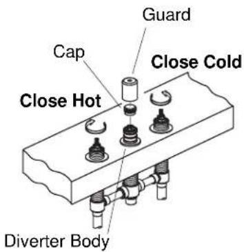
Guard Cap Close Cold Close Hot Diverter Body1. Remove the Guard and Cap

WARNING: Risk of personal injury. Supply lines may be pressurized. Do not lean over the diverter body while turning or removing the guard or cap.
☐ Make sure that the valves are closed. (Cold = fully counterclockwise; hot = fully clockwise.)
□ Turn off the main water supply.
□ Wrap a rag around the cap to prevent water spray.
IMPORTANT! Water may spray from the diverter body when you remove the cap.
□ Carefully remove the cap.
□ Discard the guard and cap.
text_image
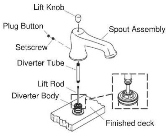
Lift Knob Plug Button Setscrew Diverter Tube Lift Rod Diverter Body Spout Assembly Finished deck2. Install the Spout
IMPORTANT! Keep the diverter body and tube clean to avoid damage to the O-ring seal.
□ Install the lift rod into the threaded rod in the diverter body. Make sure that the lift rod bottoms out against the threaded rod. It may be necessary to lift up and hold the diverter body's threaded rod with a pair of pliers during this install.
□ Install the diverter tube over the lift rod into the diverter body.
☐ Loosen the spout setscrew until it is clear of the inside wall of the spout.
□ Apply a ring of plumbers putty or other sealant around the underside of the spout base according to the manufacturer's instructions.
☐ Position the spout over the lift rod, diverter tube, and diverter body. Carefully press down until the spout contacts the finished deck.
□ Rotate the spout until it is aligned to face straight forward.
□ Tighten the setscrew.
☐ Insert the plug button over the setscrew and press into the spout.
□ Install the lift knob onto the lift rod.
□ Remove any excess putty or sealant.

text_image
Handle Apply plumbers putty. Screw Brass Spline Adapter Valve Stem Valve Body Valve Stem Height Measurement Plastic Spline Adapter Threaded Sleeve Finished Surface Hot Cold Orientation of Handles in Off Position3. Install the Handles
□ Remove the plaster guards.
☐ Measure the distance from the top of the valve stem to the finished surface.
☐ For a valve stem height between 1-13/16" (4.6 cm) and 2-1/8" (5.4 cm) use a brass spline adapter and screw. For a valve stem height between 2-1/8" (5.4 cm) and 2-5/16" (5.9 cm) use a plastic spline adapter.
☐ If the brass spline adapter is required, slide the spline adapter onto the valve stem and attach with the screw.
☐ If the plastic spline adapter is required, slide the spline adapter onto the valve stem.
☐ Position the handle assemblies facing in opposite directions away from the spout.
NOTE: The spline adapter allows fine adjustment of the handle alignment. To adjust, remove the handle and reposition the spline adapter.
□ Align the handle.
□ Reinstall the handle and check alignment.
natural_image
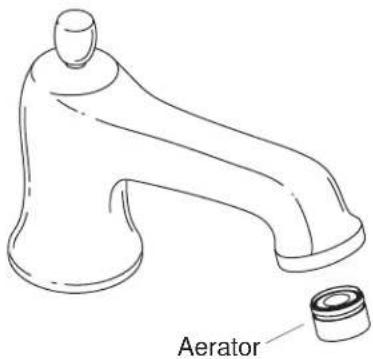
Line drawing of a faucet with a labeled component (no text or symbols on the diagram itself)4. Installation Checkout
☐ Verify the handle valves are closed. (Hot = clockwise; cold = counterclockwise.)
□ Make sure that all connections are tight.
□ Remove the aerator assembly.
☐ Turn on the main water supply and check for leaks.
☐ Turn on the hot and cold valves and run water through the spout to remove debris. Check for leaks.
□ Confirm proper diverter operation.
☐ Turn the hot and cold handles to the off position and then back to the on position. Verify that the water flow is diverted back to the spout.
□ Close the hot and cold valves to turn off the water.
□ Remove any debris from the aerator.
□ Reinstall the aerator assembly.