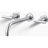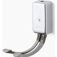
K-13816 - Faucet KOHLER - Free user manual and instructions
Find the device manual for free K-13816 KOHLER in PDF.


User questions about K-13816 KOHLER
0 question about this device. Answer the ones you know or ask your own.
Ask a new question about this device
Download the instructions for your Faucet in PDF format for free! Find your manual K-13816 - KOHLER and take your electronic device back in hand. On this page are published all the documents necessary for the use of your device. K-13816 by KOHLER.
USER MANUAL K-13816 KOHLER
natural_image
Simple line drawing of a rectangular electronic component with two curved leads (no text or symbols)Mproduct numbers are for Mexico (i.e. K-12345M)
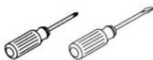
Various
Screwdrivers
Plus:
• Three (3) Flathead Screws
Before You Begin
□ Shut off the main water supply.
□ Observe all local plumbing codes and building codes.
□ Provide sufficient reinforcement to the wall.
☐ Select flathead screws that are long enough to secure the base of the foot control to the finished wall.
☐ Kohler Co. reserves the right to make revisions in the design of products without notice, as specified in the Price Book.
text_image
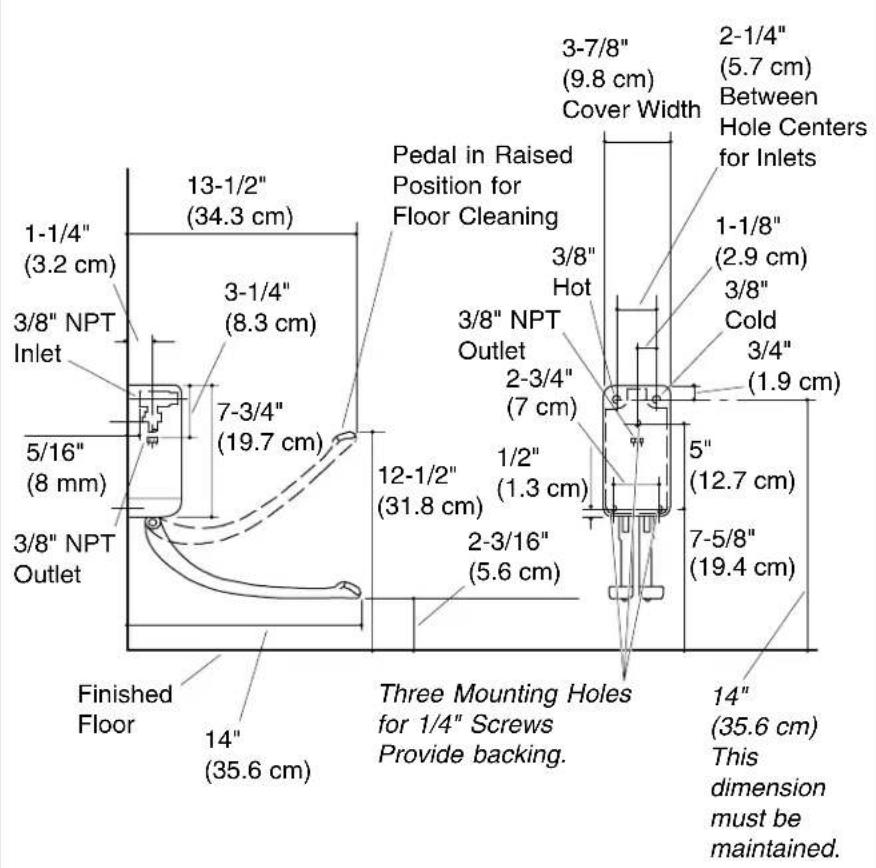
1-1/4" (3.2 cm) 3/8" NPT Inlet 5/16" (8 mm) 3/8" NPT Outlet Finished Floor 14" (35.6 cm) 13-1/2" (34.3 cm) 3-1/4" (8.3 cm) 7-3/4" (19.7 cm) 12-1/2" (31.8 cm) 2-3/16" (5.6 cm) Three Mounting Holes for 1/4" Screws Provide backing. Pedal in Raised Position for Floor Cleaning 3/8" Hot 3/8" NPT Outlet 2-3/4" (7 cm) 1/2" (1.3 cm) 2-3/16" (5.6 cm) 3-7/8" (9.8 cm) Cover Width 2-1/4" (5.7 cm) Between Hole Centers for Inlets 1-1/8" (2.9 cm) 3/8" Cold 3/4" (1.9 cm) 5" (12.7 cm) 7-5/8" (19.4 cm) 14" (35.6 cm) This dimension must be maintained.Roughing-In
Kohler Co. 3 105345-2-AC
text_image
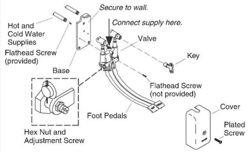
Hot and Cold Water Supplies Flathead Screw (provided) Secure to wall. Connect supply here. Valve Key Base Flathead Screw (not provided) Foot Pedals Hex Nut and Adjustment Screw Cover Plated Screw1. Install the Foot Control
Secure the Base
☐ Securely tighten the base to the valve with three flathead screws (provided).
□ Connect the lavatory or sink supply to the valve. Refer to the instructions packed with the lavatory or sink supply.
NOTE: Before securing the base to the finished wall, make sure that sufficient reinforcement has been added to the finished wall.
☐ Using three (3) flathead screws (not provided), secure the base to the finished wall.
Connect the Supplies
□ Apply thread sealant to both the hot and cold water supplies.
□ Connect the hot and cold water supplies to the valve.
□ Fit the cover in place over the valve and base.
NOTE: If the foot pedals make contact with the cover, the height of the foot pedals must be adjusted. Remove the cover from the valve
Install the Foot Control (cont.)
and base. Loosen the hex nuts on the adjustment screws until the foot pedals are even and will no longer touch the cover. Retighten the hex nuts. Reinstall the cover over the valve and base, then recheck the height of the pedals.
Installation Checkout
□ Turn on the water supply.
□ Using the key (provided), fully open the valve supply stops. Check for leaks and repair as needed.
□ Secure the cover to the valve with the plated screw.