Bedpan K-13960 - Faucet KOHLER - Free user manual and instructions
Find the device manual for free Bedpan K-13960 KOHLER in PDF.


User questions about Bedpan K-13960 KOHLER
0 question about this device. Answer the ones you know or ask your own.
Ask a new question about this device
Download the instructions for your Faucet in PDF format for free! Find your manual Bedpan K-13960 - KOHLER and take your electronic device back in hand. On this page are published all the documents necessary for the use of your device. Bedpan K-13960 by KOHLER.
USER MANUAL Bedpan K-13960 KOHLER
Mproduct numbers are for Mexico (i.e. K-12345M)
Drill and 9/16" or larger bit
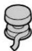
Thread Sealant Tape
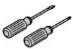
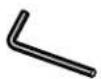
5/32"
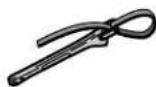
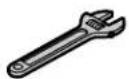
Strap Wrench
Plus:
- Seat Wrench (Kohler #21334)
• 2 1/2" IPS Pipe Nipples
• Three (3) flathead screws
• Rags
Before You Begin

CAUTION: Riskofpropertydamage. To support the bedpan washer and piping, provide sufficient reinforcement or mounting brackets as required inside the finished wall.
□ Observe all local plumbing codes and building codes.
□ Shut off the main valve and water supply.
☐ Select flathead screws that are long enough to secure the base of the foot control to the finished wall.
text_image
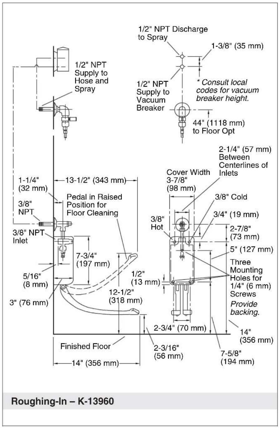
1/2" NPT Supply to Hose and Spray 1-3/8" (35 mm) 1/2" NPT Supply to Vacuum Breaker * Consult local codes for vacuum breaker height. 44" (1118 mm) to Floor Opt 1-1/4" (32 mm) 13-1/2" (343 mm) Pedal in Raised Position for Floor Cleaning Cover Width 3-7/8" (98 mm) 2-1/4" (57 mm) Between Centerlines of Inlets 3/8" Cold 3/4" (19 mm) 3/8" Hot 2-7/8" (73 mm) 5" (127 mm) Three Mounting Holes for 1/4" (6 mm) Screws Provide backing. 1/2" (13 mm) 12-1/2" (318 mm) 5/16" (8 mm) 3" (76 mm) 2-3/4" (70 mm) 14" (356 mm) Finished Floor 2-3/16" (56 mm) 7-5/8" (194 mm) Roughing-In - K-13960Kohler Co. 3 1034416-2-C
text_image
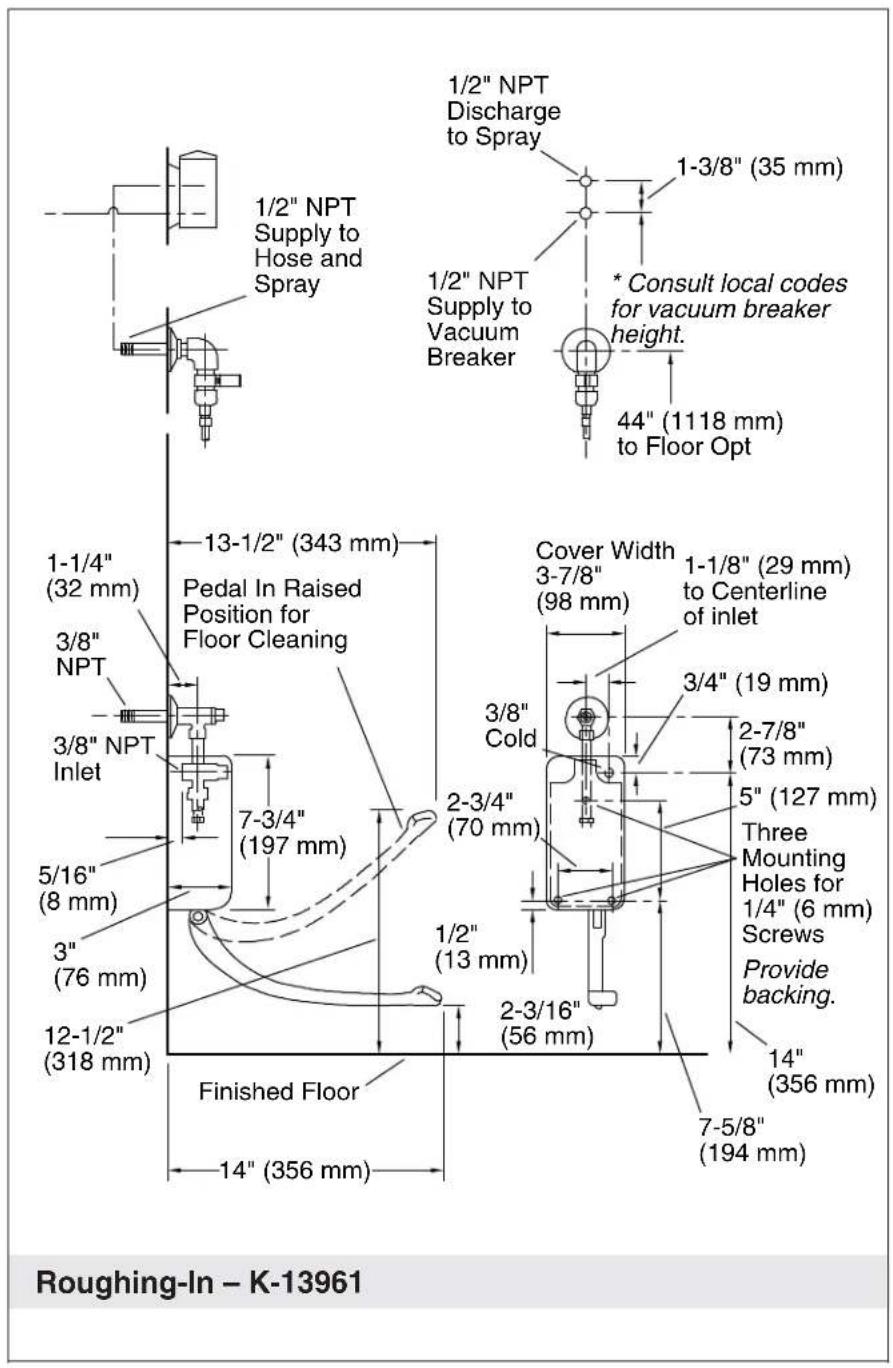
1/2" NPT Supply to Hose and Spray 1/2" NPT Discharge to Spray 1-3/8" (35 mm) 1/2" NPT Supply to Vacuum Breaker * Consult local codes for vacuum breaker height. 44" (1118 mm) to Floor Opt 1-1/4" (32 mm) 13-1/2" (343 mm) Pedal In Raised Position for Floor Cleaning Cover Width 3-7/8" (98 mm) 1-1/8" (29 mm) to Centerline of inlet 3/8" NPT 3/8" NPT Inlet 7-3/4" (197 mm) 3/4" (19 mm) 2-7/8" (73 mm) 5" (127 mm) Three Mounting Holes for 1/4" (6 mm) Screws Provide backing. 1/2" (13 mm) 12-1/2" (318 mm) 2-3/16" (56 mm) 14" (356 mm) Finished Floor 7-5/8" (194 mm) Roughing-In - K-139611034416-2-C 4 Kohler Co.
1. Prepare the Site

CAUTION: Riskofpropertydamage. To support the bedpan washer and piping, provide sufficient reinforcement or mounting brackets as required inside the finished wall.
□ Refer to the "Roughing-In" section for your particular model.
☐ Plumb using 1/2" NPT pipe, or 3/8" NPT pipe, or 1/2" copper tubing, elbows, and adapters. Secure the piping to reinforcements in the wall.
☐ Provide pipe holes in the wall according to the roughing-in diagram.
□ Complete the finished wall.
text_image
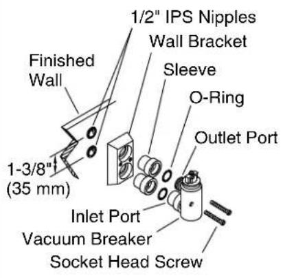
Finished Wall 1-3/8" (35 mm) 1/2" IPS Nipples Wall Bracket Sleeve O-Ring Outlet Port Inlet Port Vacuum Breaker Socket Head Screw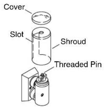
text_image
Cover Slot Shroud Threaded Pin2. Install the Vacuum Breaker
Attach

CAUTION: Riskofpropertydamage. Do not subject the vacuum breaker to continuous pressure for more than 12 hours.
NOTE: Install the vacuum breaker at least 6"(152 mm) above the fixture rim. Consult local codes for vacuum breaker height.
NOTE: Apply thread sealant where applicable.
☐ Thread a 1/2"IPS nipple into each supply outlet piping and supply inlet piping on the finished wall. Ensure that the threads of each 1/2"IPS nipple extend beyond the finished wall.
☐ Slide the wall bracket over both of the 1/2"IPS nipples until it is snug against the finished wall.
☐ Insert one sleeve through each hole of the wall bracket, then thread each sleeve onto each 1/2"IPS nipple.
□ Using a seat wrench, tighten each sleeve. Do not overtighten.
☐ Confirm that an O-ring is located in the outlet port and inlet port of the vacuum breaker. If not present, reinstall the O-ring(s).
☐ Slide the vacuum breaker into both sleeves at the same time. Secure with two socket screws. Tighten the socket screws with a 5/32"hex wrench. Do not overtighten.
Cover
Install the Vacuum Breaker (cont.)
□ Rotate the shroud so the slot faces the finished wall.
□ Slide the shroud over the vacuum breaker.
☐ Ensure that the threaded pin comes through the hole at the top of the shroud.
☐ Hand tighten the cover onto the threaded pin.
text_image
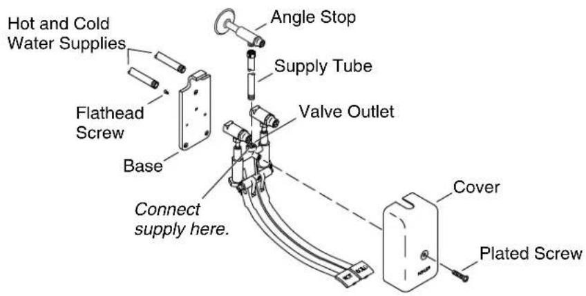
Hot and Cold Water Supplies Flathead Screw Base Connect supply here. Angle Stop Supply Tube Valve Outlet Cover Plated Screw3. Install the Foot Control Unit
Mount
□ Align the screw holes and place the base onto the back of the valve. Secure with three flathead screws (provided).
□ Apply thread sealant to the hot and cold water supplies.
□ Connect the cold and hot water supplies to the valve.
☐ Secure the valve with base to the finished wall with three flathead screws (not provided).
Connect
□ Apply thread sealant to the supply tube.
□ Connect the supply tube to the valve outlet and angle stop.
Cover
□ Slide the cover over the valve.
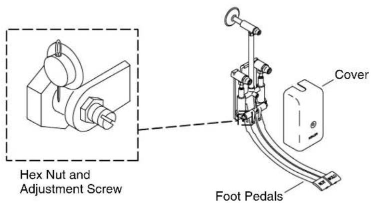
☐ Ensure that the cover does not have contact with the foot pedal(s). If the height of the foot pedal(s) needs to be adjusted, refer to the "Adjust the Foot Pedal(s)" section.
□ Secure the cover to the valve with a plated screw.
text_image
Hex Nut and Adjustment Screw Foot Pedals Cover4. Installation Checkout
NOTE: If the height of the foot pedal(s) needs to be adjusted, follow the procedure below.
□ Remove the cover from the valve.
□ Loosen the hex nut.
NOTE: For foot controls with two pedals, both foot pedals must be at the same height as one another.
☐ Turn the adjustment screw counterclockwise until the foot pedal will no longer touch the cover.
□ Retighten the hex nuts.
☐ Reinstall the cover over the valve, then recheck the height of the pedal(s).
□ Secure the cover to the valve with a plated screw.
text_image
Supply Outlet Supply Clamp Aerator Nozzle Hose5. Install the Hose Assembly
Install the Hose Assembly
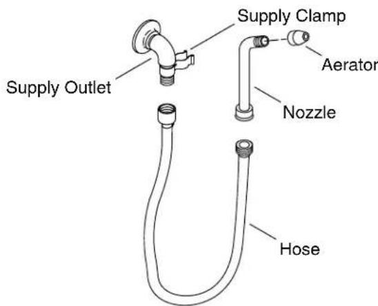
□ Apply thread sealant to each end of the hose.
□ Securely tighten one end of the hose into the supply outlet.
□ Securely tighten the other end of the hose into the nozzle.
□ Hang the nozzle from the supply clamp.
Installation Checkout
☐ Foronepedalbedpanwashers: Using the key provided, open both the check valve and the supply valve.
☐ Fortwopedalbedpanwashers: Using the key provided, open both the check valve and the supply valve for each pedal.
□ Check for leaks. Repair as needed.
Clean the Aerator
☐ Turn the aerator clockwise to remove it from the nozzle.
□ Run water through the nozzle for approximately one minute to remove debris.
□ Test and verify that the nozzle operates normally.
□ Reinstall the aerator to the nozzle.