AQUA200i - Rowing Machine VirtuFit - Free user manual and instructions
Find the device manual for free AQUA200i VirtuFit in PDF.

| Brand | VirtuFit |
| Model | AQUA200i |
| Product type | Water resistance rowing machine |
| Maximum user weight | 120 kg |
| Use | Domestic |
| Console power supply | 4 AA 1.5 V batteries |
| Resistance levels | 6 levels (adjustment by water level) |
| Water tank capacity | Maximum level 6 (do not exceed) |
| Tank material | Plastic (water tank) |
| Display | Console with LCD screen: calories, strokes, distance, mode |
| Console functions | ON/OFF, MODE, ▲, ▼, RESET, CAL, STROKES, KM/MI |
| App compatibility | FitShow, Kinomap (via Bluetooth) |
| Tank filling | Manual pump or funnel included |
| Tank draining | Manual pump |
| Purification tablet | Included (to be added every 6 months) |
| Wheel type | Wheels for moving (front stabilizer) |
| Required space dimensions | 1 to 2 meters behind the machine |
| Operating temperature | 10 °C to 35 °C |
| Storage temperature | 5 °C to 45 °C |
| Maintenance | Daily cleaning, annual lubrication, semi-annual bolt check |
| Warranty | Warranty voided in case of improper use or unauthorized modification |
Frequently Asked Questions - AQUA200i VirtuFit
User questions about AQUA200i VirtuFit
0 question about this device. Answer the ones you know or ask your own.
Ask a new question about this device
Download the instructions for your Rowing Machine in PDF format for free! Find your manual AQUA200i - VirtuFit and take your electronic device back in hand. On this page are published all the documents necessary for the use of your device. AQUA200i by VirtuFit.
USER MANUAL AQUA200i VirtuFit
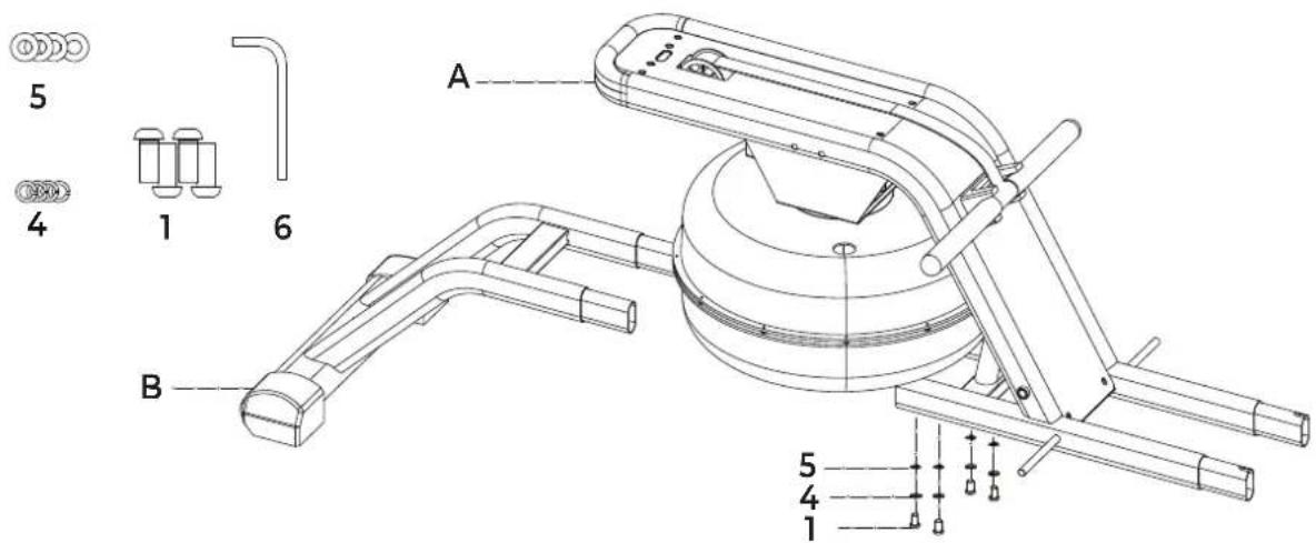
B Front rail assembly 1
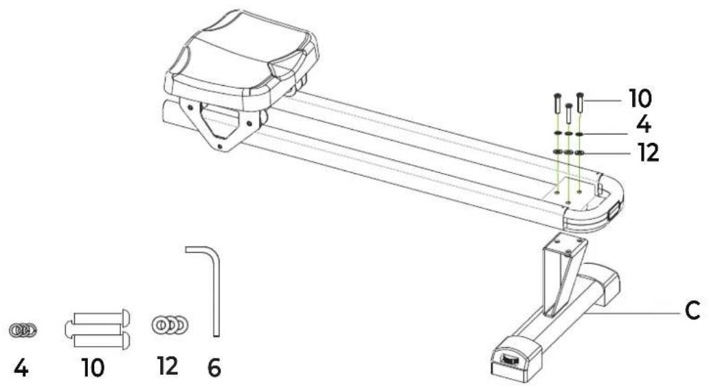
C Rear support assembly 1
D Console bracket 1
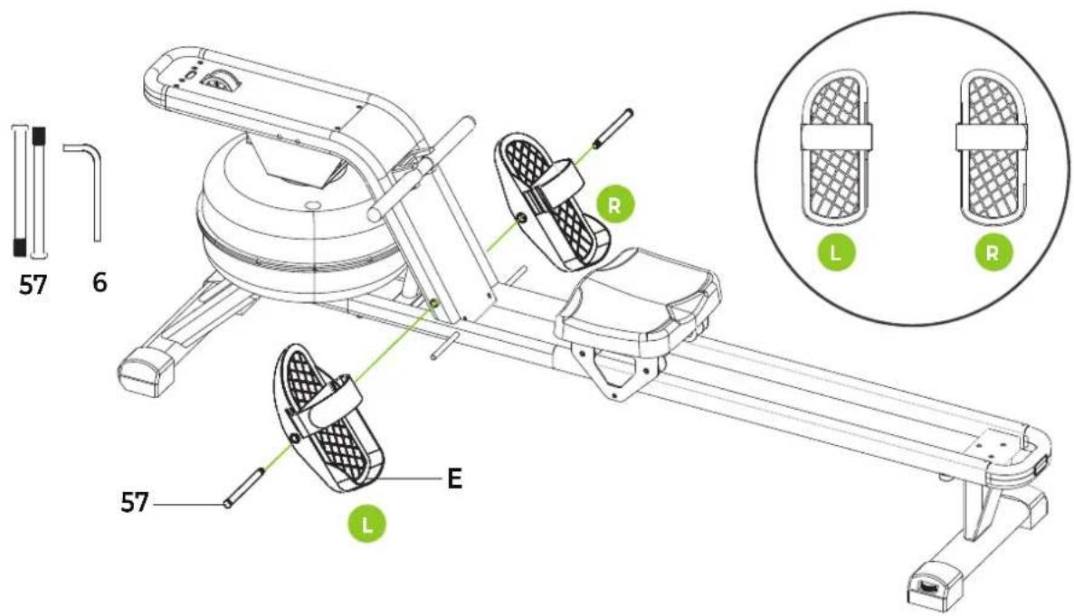
E Foot plate 2
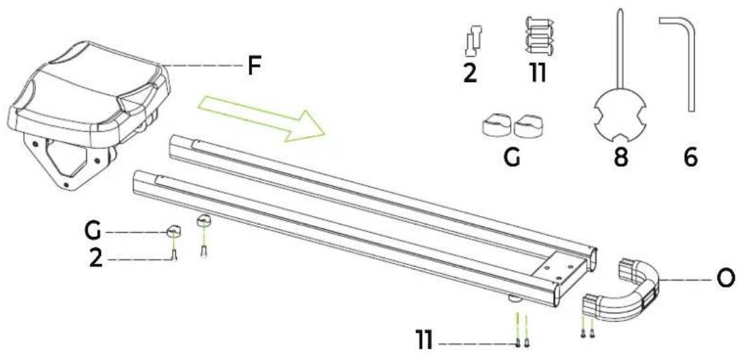
F Seat assembly 1
G Limit block 2
# DESCRIPTION QTY
57 Pedal shaft 2
T Funnel
H Sliding rail assembly 1
I Console 1
J Hardware kit 1
R Pumps 1
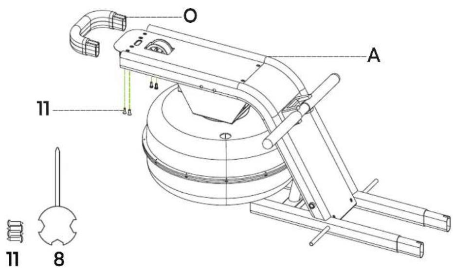
O Hand cover 2
STEP 01
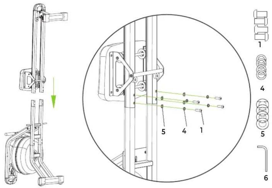
STEP 02
STEP 03
STEP 04
STEP 05
STEP 06
STEP 07
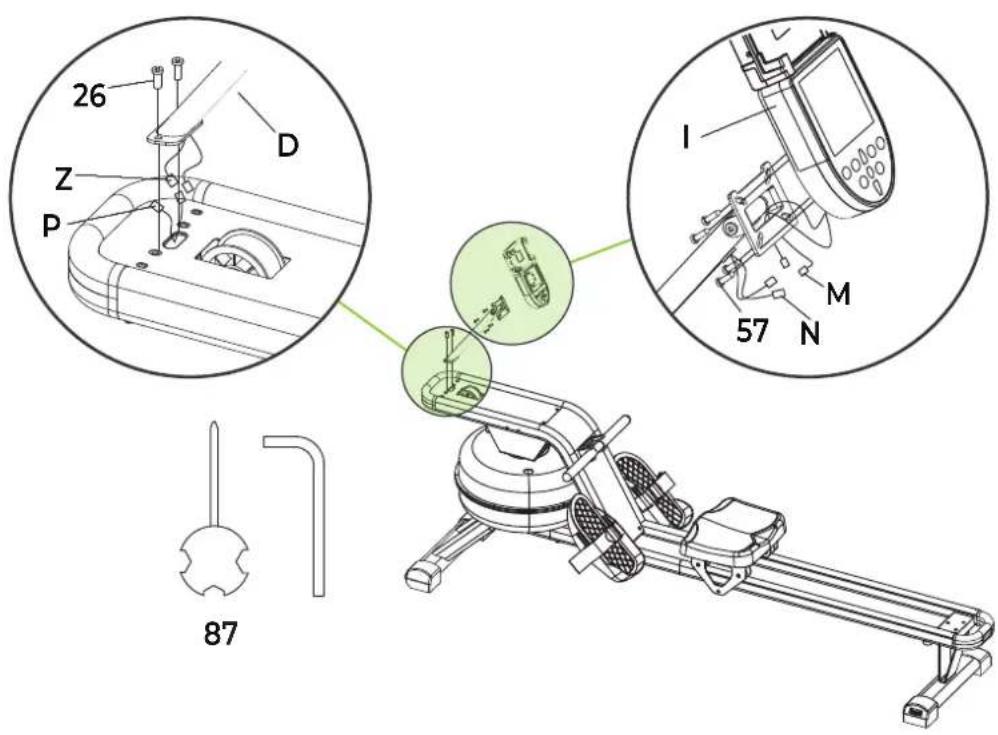
FIG. A
natural_image
Line drawing of a mobile phone with front panel and keypad (no text or symbols)FIG. B

natural_image
Line drawing of a person bending forward with hands raised (no text or symbols)1
natural_image
Line drawing of a person sitting cross-legged, holding their head in thought (no text or symbols)2
natural_image
Line drawing of a person performing a seated stretch or exercise (no text or symbols)3

natural_image
Line drawing of a person in motion, viewed from the side (no text or symbols)4

natural_image
Line drawing of a person performing a stretching exercise with arms raised (no text or symbols)5
INDEX
| Safety instructions | 09 | |
| Guarantee | 09 | |
| Assembly instructions 09 | ||
| Adjusting | 10 | |
| Moving and storage 10 | ||
| Filling and emtying the water tank 10 | ||
| Training with fitness apps 11 | ||
| Maintenance | 11 | |
| Console | 12 | |
| Training guidelines | 12 | |
SAFETY INSTRUCTIONS

WARNING
Consult your doctor before you start exercising. This is particularly important for people with health problems. Please read all instructions before using the machine. VirtuFit assumes no responsibility for injury or property damage resulting from the use of this equipment. Please read this manual carefully before assembling and/or using the machine.
- Make sure that the machine is properly assembled and that all nuts and bolts are tight before using it.
- Lubricate all moving parts annually with petroleum jelly (acid-free) or silicone spray.
- Do not wear loose clothing to avoid getting caught in moving parts.
• Install and use the unit on a solid, level surface.
• Always wear clean sports shoes when using the appliance.
- Keep children and pets away from the appliance when in use.
- Maintain your balance when using the device.
- Do not place your fingers or other objects in the moving parts.
- Before exercising, consult your physician to determine the appropriate frequency, duration and intensity of exercise for your age and physical condition. Stop exercising immediately if you experience nausea, shortness of breath, fainting, headache, chest pain, tightness or any other discomfort.
- Do not hold the machine by the seat when moving.
• This machine should only be used by one person at a time. - This machine is designed for domestic use and the maximum user weight is 120 kg.
- Leave 1-2 metres of space behind the machine to avoid accidents.
- Place the machine on a clean, flat surface. Do not place it on a thick carpet, as this may hinder the ventilation of the machine. Do not place the machine outdoors or near water.
- Keep the storage area dry, clean and level to prevent damage. Do not use the device for any purpose other than training.
- Use the device only in an environment where the ambient temperature is between 10^ and 35^ . Store the device only in an environment where the temperature is between 5^ and 45^ .
GUARANTEE
Warranty claims are excluded if the cause of the defect is the result of:
- Maintenance and repair work not carried out by an official dealer.
- Improper use, negligence and/or poor maintenance.
- Failure to maintain the appliance in accordance with the manufacturer's instructions.
ASSEMBLY INSTRUCTIONS (STEP 01-07)
Missing parts: If any parts are missing from the packaging, carefully check the polystyrene foam and the appliance itself. Some parts (bolts, screws, etc.) are already attached to the unit.
Error message: Make sure that all cables are carefully attached. The aluminium feet of the console are very sensitive and must be kept straight. If the console gives an error message after the machine has been mounted, the aluminium feet of the console may be bent. Straightening the aluminium feet may make the error message disappear.
Hex head bolts: Make sure that the hex head spanner is pushed into the bolt before applying force. This will prevent the head of the socket bolt from turning.
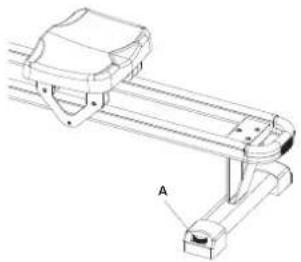
ADJUSTING
Level
Adjust the adjustable end caps at the rear of the rear stabiliser (A) by turning the wheel.
NOTE! Fingers can be trapped between moving parts, such as the seat. Keep hands away from the rails when adjusting and using the unit.
natural_image
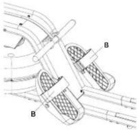
Technical line drawing of a mechanical linkage or support structure (no text or symbols)Adjusting the pedal
The pedal strap (B) is adjustable and can be adjusted to the size of the user's foot.
MOVING AND STORAGE
NOTE! Slide the seat to the front of the rails, otherwise the seat will slide when the unit is in the upright position.
Moving
Raise the rear stabiliser until the front stabiliser wheels touch the ground. With the wheels on the ground, the machine can easily be moved to the desired location.

natural_image
Line drawing of a person pushing a wheeled cart on a flat surface (no text or symbols)NOTE! The seat slides when the machine is in the upright position.
Storage
CAUTION! Store the tool in a dry place, out of the reach of children. Make sure that the tool is stable and safe so that it cannot fall on children or animals.
Move the unit to the desired location and lift the rear stabilizer (B) fully up until the rowing machine is vertical.

natural_image
Technical line drawing of a rowing machine with labeled components (no text or symbols present)NOTE! If the rower is not used for more than one month, empty the water tank first.
FILLING AND EMPTYING THE WATER TANK
CAUTION!
· Always fill the tank with tap water only and add a water purification tablet. Never use chlorinated water or chlorine. This can damage the tank and void the warranty.
- Add a water purification tablet once every six months. If the water remains cloudy, replace the water in the tank.
- The water in the tank is not consumable. Discard the water after it has been pumped out of the tank.
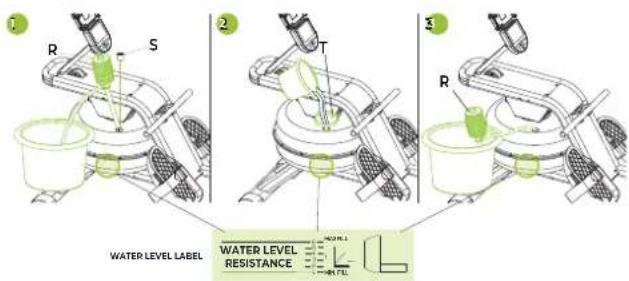
Fill the water tank (1+2)
- Remove the water tank cap (S) from the top water tank opening. The water tank can be filled in two ways.
- Manual water pump (R): Insert the hose end of the manual
water pump (R) into the bucket filled with water and insert the other end of the hose into the water tank opening. Press the hand water pump (R) to fill the water tank.
- Funnel (T): Insert the funnel (T) into the opening of the water tank and pour a bucket full of water through the funnel into the water tank.
- Look at the side of the water tank to see what the water level is in the tank.
- Replace the water tank closing cap (S) on the opening of the water tank, so that it is properly closed.
NOTE!
- You can read the water level on the side of the tank. Fill to maximum level 6. The warranty will be voided if the water tank is filled above level 6.
- The resistance depends on the water level in the tank. Level 1 is the lowest resistance and level 6 is the highest resistance.
Emptying the water tank (3)
- Remove the water tank cap (S) from the top water tank opening.
- Place an empty bucket next to the water tank and insert the end of the manual water pump hose (R) into the empty bucket. Insert the other end of the hose into the opening of the water tank. Squeeze the hand water pump (R) to empty the water tank.
- When the water tank is empty, dry it with a cloth.
- Replace the water tank closing cap (S) on the opening of the water tank, so that it is properly closed.
TRAINING WITH FITNESS APPLICATIONS
VirtuFit does not provide service for third party fitness applications such as Kinomap, iConsole, FitShow etc. If you encounter problems with a third party fitness application, please contact the developer of the application in question.
Instruction
- To scan the QR code with an Android or IOS phone or tablet, a QR code scanner is required. The app for scanning QR codes can be downloaded from the App Store or Google Play Store.
- Scan one of the QR codes below to go directly to the App Store or Google Play Store page where the fitness app can be downloaded.
- Scan the QR code on the right to access the fitness app manual. The manual describes step by step how to connect the
fitness app to the device, how the fitness app works and what its capabilities are.
Fitshow

APP STORE

GOOGLE PLAY

MANUAL
Kinomap

APP STORE

GOOGLE PLAY

MANUAL
MAINTENANCE
Safe and efficient use can only be achieved if the appliance is properly installed and maintained. It is your responsibility to ensure that the appliance is maintained regularly. Parts that have been used and/or damaged must be replaced before the appliance is used again. The appliance should only be used and stored indoors. Long-term exposure to weather and temperature/humidity changes can have a serious impact on the electrical components and moving parts of the unit. Always unplug the power cord from the unit before cleaning or servicing it.
Daily maintenance
- Clean and remove sweat and moisture after each use.
- Check that the unit is free of dust and dirt.
- Do not use aggressive cleaning agents and keep the device away from moisture.
Semi-annual maintenance
- Clean and remove sweat and moisture after each use.
- Check that the unit is free of dust and dirt.
- Do not use aggressive cleaning agents and keep the device away from moisture.
CAUTION!
- All repairs must be performed by a professional technician, unless otherwise specified by the supplier or manufacturer.
Cleaning
General cleaning of the machine will prolong its life. Keep the machine clean by dusting it regularly. Regular maintenance extends the life of your machine and prevents accidents! For more information, please visit https://www.virtufit.nl/service/faq/
CAUTION! Wear clean shoes to reduce the risk of soiling the machine.
Battery
AA BATTERIES
The display uses AA batteries, which are replaceable on the back of the display. The batteries must be inserted correctly.
If the screen is unreadable or only parts of the image work, proceed as follows:
- Remove the batteries and wait 15 seconds.
- Replace the batteries correctly.
Tips on using the battery
- Remove the batteries from the screen when they are empty or when the camera will not be used for a long period of time.
- Do not recharge, disassemble or dispose of batteries in fire.
- Pay close attention to the + and - when inserting the batteries. When replacing batteries, it is recommended to replace all batteries, do not mix old and new batteries.
- It is recommended to use alkaline batteries, they have a longer life than normal batteries.
- Batteries should be replaced when the display loses brightness or stops showing.
Battery replacement
- If the display is not accurate, it is recommended to replace the batteries.
- Use 2 x AA batteries for power.
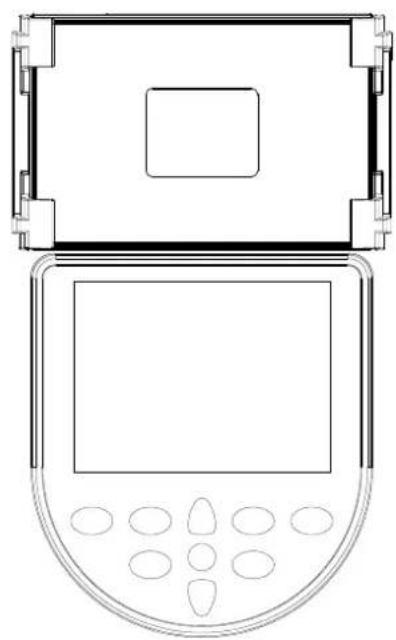
CONSOLE (FIG. A)

natural_image
Simple line drawing of a mobile phone with a blank screen and keypad (no text or symbols)Buttons
-
ON/OFF Press briefly to switch the device on. Press and hold for three seconds to switch the device off.
• MODE Switch between different modes. -
▲ UP Increase value.
- ▼ DOWN Decrease value.
-
RESET Press briefly to reset current settings. Press and hold for three seconds to reset all values.
-
CAL Displays calories consumed.
• STROKES Displays the number of strokes. - KM/MI Displays the distance.
NOTE!
- If there is no movement for more than 4 minutes, the console will automatically shut down.
- When paired with an app, the console does not go into sleep mode automatically.
TRAINING GUIDELINES (FIG. B, 1-5)
A successful training program includes a warm-up, the actual training and a cool-down. Perform the complete training program at least twice, but preferably three times a week and keep a rest day between training sessions. After a few months, the intensity of the training can be increased, for example to four or five times a week.
The warm-up
The purpose of a warm-up is to prepare the body for training and to reduce the risk of injury. Warm up your body for two to five minutes before starting a cardio or strength training session. Do exercises that increase the heart rate and warm up the working muscles. Examples of this type of activity are running, jogging, jumping jacks, skipping and running in place.
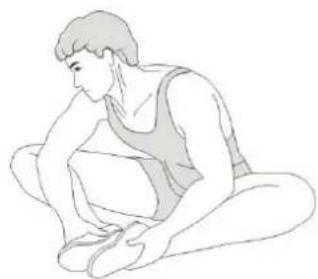
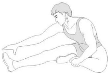
Stretching
Stretching while the muscles are warm is very important after a good warm-up and cool-down. It reduces the risk of injury. Stretching exercises should be held for 15-30 seconds. Here are some examples of stretching exercises:
- Toe touch (Fig. B-1)
• Inner thight stretch (Fig. B-2)
• Hamstring stretch (Fig. B-3) - Achilles stretch (Fig. B-4)
- Side stretch (Fig. B-5)
Cooling
down
The purpose of the cool-down is to return the body to its (near) normal resting position at the end of the workout. A good cool-down slowly reduces your heart rate and promotes recovery.
INHOUD
natural_image
Technical line drawing of a mechanical linkage or support structure with labeled component A (no text or symbols beyond label)VERPLAATSEN EN OPBERGEN
natural_image
Line drawing of a person using a mobility device to lift a person's arm (no text or symbols)natural_image
Technical line drawing of a rowing machine with labeled components and a side view showing a cylindrical component (no text or symbols present)natural_image
Simple line drawing of a handheld electronic device with a screen and keypad (no text or symbols)Toetsen
natural_image
Technical line drawing of a mechanical linkage or support structure (no text or symbols)natural_image
Line drawing of a person using a mechanical lever system (no text or symbols)natural_image
Technical line drawing of a rowing machine with two views: one showing internal components and the other a vertical support structure (no text or labels)natural_image
Line drawing of a mobile phone with a blank screen and control buttons (no text or symbols)Tasten
natural_image
Technical line drawing of a mechanical linkage or bracket assembly (no text or symbols)DÉPLACEMENT ET STOCKAGE
natural_image
Line drawing of a person using a manual lawn tool on a paved surface (no text or symbols)natural_image
Technical line drawing of a rowing machine with labeled components (no text or symbols present)natural_image
Simple line drawing of a mobile phone with control buttons (no text or symbols)Boutons
DESCRIPTION QTY.
| 1 Inner hex head screw M8×15 8 | ||
| 2 Inner hexagon cylindrical head screw M6*16 4 | ||
| 3 Inner hex head screw M8*30 2 | ||
| 4 spring washer D8 11 | ||
| 5 Arc gasket D8 8 | ||
| 6 Inner hexagon wrench S4 1 | ||
| 7 Inner hexagon wrench S5 1 | ||
| 8 The cross is a wrench 1 | ||
| 9 No.10 opening wrench | 1 | |
| 10 | Inner hex head screw M8×40 | 7 |
| 11 | Cross-head tapping screw ST4.2×16 | 22 |
| 12 | flat washer | 3 |
| 13 | Water tank mouth plug | 1 |
| 14 | Cross slot head screw M3×20 | 12 |
| 15 | Cover the water tank | 1 |
| 16 | awe | 1 |
| 17 | Water tank seal ring | 1 |
| 18 | Water tank under the cover | 1 |
| 19 | Nylon nut M3 | 12 |
| 20 | Cross-head tapping screw ST4.2*10 | 2 |
| 21 | Sensing head | 1 |
| 22 | The Retractor is fixed on the plate | 1 |
| 23 | The upper shaft sleeve | 1 |
| 24 | Armor tube | 1 |
| 25 | guard | 1 |
| 26 | Inner hex flat head screw M6*10 | 16 |
| 27 | The pullback assembly | 1 |
| 28 | Inner hex head screw M6*25 6 | |
| 29 | Plastic bearing seat | 1 |
| 30 | Retractor mounting assembly | 1 |
| 31 | elastomer gasket | 2 |
| 32 | rubber washer | 1 |
| 33 | Tank shaft sleeve | 1 |
| 34 | stationary pin | 1 |
| 35 | flat washer | 1 |
| 36 | elastic washer | 1 |
| 37 | Inner hex head screw M8×20 | 1 |
| 38 | Inner hexagon cylindrical head screw M10*55 | 1 |
DESCRIPTION QTY.
| 39 | deep groove ball bearing | 6 |
| 40 | Small woven belt wheel | 2 |
| 41 | Nylon nut M10 1 | |
| 42 | New big pulley | 1 |
| 43 | Rack assembly | 1 |
| 44 | Front slide rail assembly | 1 |
| 45 | The handle seat | 1 |
| 46 | Sliding rail assembly | 1 |
| 47 | Backfoot tube assembly | 1 |
| 48 | Limit wheel | 2 |
| 49 | Hand cover | 2 |
| 50 | The cable plug | 2 |
| 51 | Electronic table seat assembly | 1 |
| 52 | Inner hexagon cylindrical head screw M6*70 | 1 |
| 53 | axle sleeve | 2 |
| 54 | Nylon nut M6 | 1 |
| 55 | electronic meter | 1 |
| 56 | Electronic table fixed board | 1 |
| 57 | Cross slot head screw | 4 |
| 58 | funnel | 1 |
| 59 | Manual pump | 1 |
| 60 | pedal spindle | 2 |
| 61 | Left foot | 1 |
| 62 | Magic tie | 2 |
| 63 | Right foot | 1 |
| 64 | Open-core rivets | 4 |
| 65 | edgings | 2 |
| 66 | Limit pad | 2 |
| 67 | PVC grips | 2 |
| 68 | Woven belt wheel shaft | 2 |
| 69 | Rubber mat 2 | 2 |
| 70 | After adjustable foot sleeve | 2 |
| 71 | Spacer welding assembly | 2 |
| 72 | flat washer D6 | 11 |
| 73 | PVC drive pipe | 4 |
| 74 | Pad roller | 4 |
| 75 | Axis with retaining ring D10 | 8 |
| 76 | Seat axle | 2 |
PARTS LIST
virtufit
DESCRIPTION QTY.
| 77 Axis with retaining ring D8 2 | |
| 78 cushion 1 | |
| 79 Left front foot sleeve 1 | |
| 80 Right front foot sleeve 1 |