
Ultimate Pro 2i - Rowing Machine VirtuFit - Free user manual and instructions
Find the device manual for free Ultimate Pro 2i VirtuFit in PDF.


| Product Type | Rowing Machine (Ergometer) |
| Brand | VirtuFit |
| Model | Ultimate Pro 2i |
| Max User Weight | 230 kg |
| Resistance Type | Air resistance (fan flywheel) |
| Display Metrics | Time, Strokes, Calories, Meters, Watts, SPM, Pulse, Time/500m, plus detailed metrics (Avg 500m Pace, Avg Meter/Stroke, Max HR, Cal/Hr, Force Curve, Max Watt, Watt Chart, Avg Watt) |
| Pre-set Programs | Quick Start, Race, Interval, Time, Distance, Custom |
| Heart Rate Monitoring | Yes (via chest strap receiver) |
| App Compatibility | Kinomap (via QR code) |
| Frame Material | Steel main frame, aluminum rail |
| Folding Design | Yes (pull pin folding mechanism) |
| Pedal Adjustment | Heel support height adjustable |
| Damper Level | Adjustable (push down) |
| Seat | Contoured cushion on roller carriage |
| Dimensions (Approx.) | Not specified in manual (estimate: ~200 cm length when unfolded) |
| Weight | Not specified (estimate ~30-40 kg) |
| Power Supply | Battery-powered (console) |
| Safety Standards | Read manual before use; keep 0.5m clearance; indoor use only; temperature range 10-35°C |
| Included Accessories | Tools for assembly, QR code for app manual |
Frequently Asked Questions - Ultimate Pro 2i VirtuFit
User questions about Ultimate Pro 2i VirtuFit
0 question about this device. Answer the ones you know or ask your own.
Ask a new question about this device
Download the instructions for your Rowing Machine in PDF format for free! Find your manual Ultimate Pro 2i - VirtuFit and take your electronic device back in hand. On this page are published all the documents necessary for the use of your device. Ultimate Pro 2i by VirtuFit.
USER MANUAL Ultimate Pro 2i VirtuFit
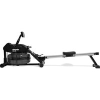
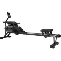
Ultimate Pro 2i Ergometer Rowing Machine
User manual
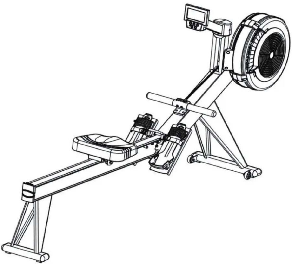
natural_image
Line drawing of a rowing machine with levers and wheels (no text or symbols)SAFETY INSTRUCTIONSSAFETY INSTRUCTIONS 3-4
CHECKLIST CHECKLIST 5-6
NOTES NOTES 7
ASSEMBLY INSTRUCTIONSASSEMBLY INSTRUCTIONS 8-14
CONSOLE CONSOLE 15 - 22
APPSAPPS 23
EXPLODED DRAWING EXPLODED DRAWING 24
PARTS LISTPARTS LIST 25 - 27
WARNING:
Before beginning any exercise program consult your physician. This is especially important for people who are over 35 years old or who have pre-existing health problems. Read all instructions before using any fitness equipment. Do not operate this device without properly fitted guards, as the moving parts can present a risk of serious injury if exposed.
ATTENTION
- It is important to read this entire manual before assembling and using the device. Safe and effective use can only be achieved if the device is assembled, maintained and used properly. It is your responsibility to ensure that all users of the device are informed of all warnings and precautions.
Before starting any exercise program, you should consult your doctor to determine if you have any medical or physical conditions that could put your health and safety at risk, or prevent you from using the device properly. Your doctor's advice is essential if you are taking medication that affects your heart rate, blood pressure or cholesterol level.
- Be aware of your body's signals. Incorrect or excessive exercise can damage your health. Stop exercising if you experience any of the following symptoms: pain, tightness in your chest, irregular heartbeat, extreme shortness of breath, lightheadedness, dizziness or feelings of nausea. If you do experience any of these conditions you should consult your doctor before continuing with your exercise program.
- Keep children and pets away from the device. The device is designed for adult use only.
- Use the device on a solid, flat level surface with a protective cover for your floor or carpet. To ensure safety, the device should have at least 0.5 metres of free space all around it.
– Before using the device, check that the nuts and bolts are securely tightened.
- The safety of the device can only be maintained if it is regularly examined for damage and/or wear and tear.
- Always use the device as indicated. If you find any defective components while assembling or checking the device, or if you hear any unusual noises coming from the device during use, stop immediately. Do not use the device until the problem has been rectified.
- Wear suitable clothing while using the device. Avoid wearing loose clothing that may get caught in the device or that may restrict or prevent movement.
- The max user weight is 230 KGS. Braking ability is independent of speed.
- The device is not suitable for therapeutic use.
- Care must be taken when lifting or moving the device so as not to injure your back. Always use proper lifting techniques and/or seek assistance if necessary.
- Please keep the space at least 1 to 2 meter at the end of base frame to escape any accidents!
- Place the device on a clean and flat surface. Do not place the device on a thick carpet.
- The device is for indoor use and not for outdoor use to prevent damage. Keep the storage location dry, clean and flat. It is forbidden to use the device for purposes other than training.
- Only use the machine in an environment with an ambient temperature between 10 °C and 35 °C. Only store the device at an ambient temperature between 5 °C and 45 °C.
Warranty claim is excluded if the cause of the defect is the result of:
– Maintenance assembly and repair work not carried out by an official dealer.
– In the event of improper use, neglect and / or poor maintenance.
- Failure to maintain the device in accordance with the manufacturer's instructions (see the enclosed manual).
TOOLKIT
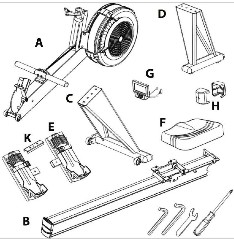
| NUMBER DESCRIPTION | |
| A | Main frame |
| B | Aluminum rails |
| C | Front stabilizer |
| D | Rear stabilizer |
| E | Pedals |
| F | Seat |
| G | Console |
| H | Console cover |
ONDERDELEN
| NUMBER DESCRIPTION SHAPE QTY. | |||
| J4 | M4 x 12.7 mm Screw 3 |  | |
| J0 | M8 Nylon Nut 2 | 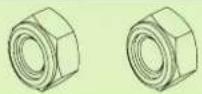 | |
| J1 | Bolt M10 x 16 mm 4 |  | |
| J2 | Washer M10 x 1.5t 4 | 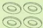 | |
| J3 | Bolt M6 x 50 mm 4 |  | |
| J5 | Bolt M8 x 25 mm 2 |  | |
| J6 | Bolt M8 x 16 mm 10 |  | |
| J7 | Washer M8x1.5t 10 |  | |
| J8 | Pull pin 1 |  | |
| J9 | Screw M4 x 10 mm 2 | 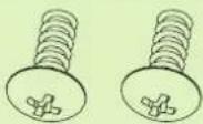 | |
| J10 | Spring washer 2 |  | |
NOTE: Before assembly please lay out ALL pieces accordingly to ensure you are not missing any items
PLEASE BE CAUTIOUS: As some components may be sharp and can cause harm if not handled correctly. Always use safety measurements when assembling any piece of equipment or machinery.
STEP 1

- For best results place Forward Base (A) (Damper Fan) upside down on a soft and secure surface. Once this is done, the pre-screwed holes for Forward Base Leg (C) will be visible. To bolt in Forward Base Leg (C) into Forward Base (A), place directly on top of pre-screwed holes. Secure with 2 (J1) Bolt(s) and (J2) Washer(s).
STEP 2
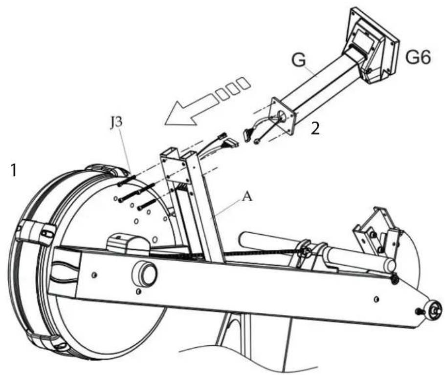
- (1) Please LIGHTLY pull wires so that they do not recede into the stem of Base Leg (A). DO NOT CUT WIRES; wires will connect to console tube when installing console. CAUTION: Please handle with care, as electrical wires are delicate. If wires are handled too aggressively they will dislocate.
• (2)Once wires are connected CAREFULLY secure Console Tube (G) to the stem of Base Leg (A). Please be careful of exposed wire ends. The wires should recede back into stem once connected in order to prevent damage or dislocation.
STEP 3
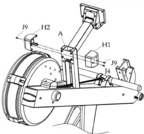
- To fi nish securing Console (G) onto Forward Base (A) please attach Place Holder (H). Place Holder (H) will break up into 2 components (H1) and (H2). These components will rejoin together once attached onto forward Base (A). Once rejoined please secure with 2 screws (J9) and 1 screw(J4).
STEP 4

- To install Rear Base Leg (D), face Base Railing (B) face down so that the receiving device for the seat cushion is on the floor. Place Rear Base Leg (D) above the pre-screwed holes of the Base Rail (B). Once placed secure with 2 (J1) Bolt(s) and (J2) washer(s).
STEP 5

- To install foot pedals (E1) and (E2) into (A) Forward Base join the together by Steel Bracket (K). Steel Bracket (K) should slide into place of Foot Pedal (E1). Once placed secure with 2 (J5) bolts, 2 (J10) spring washers and 2 (J0) nuts.
NOTE: You must install foot pedals before moving forward with the assembly process. Should Step 5 be skipped the Pre-screwed holes on the base railing would cover up the pre screwed holes on the Forward Base leg where the foot pedals are to be installed. So make sure you do not skip step 5.
STEP 6

- To install Seating place Seat Cushion (F) above the pre-screwed holes of Base Railing (B). The high angled read end of Seat Cushion (F) should face the back end of Base Railing (B). Secure with 4 Bolts (J6) and 4 washers (J7).
- To install Pull pin (J8) locate the pre-screwed bolt at the end of Forward Base (A) and turn clockwise until the bolt is securely fastened.
- Align Forward Base (A) with Base Railing (B) until the pre-screwed holes are aligned with one another. Secure Forward Base (A) to Base Railing (B) with 4 Bolts (J6) and 4 Washers (J7).
- NOTE: Please be sure to tighten and secure ALL BOLTS AND WASHERS IN THEIR PLACE TO ENSURE A SOLID AND SECURE foundation to the rower.
STEP 7
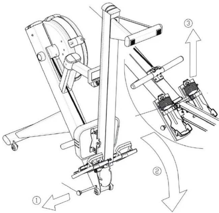
Rower storage
- To fold the VirtuFit Ultimate Pro 2i Ergometer Rowing Machine, simply pull the PULL PIN (J8) while holding the Rail Handle (B21) located between Forward Base (A) and Base Railing (B). Gently set Forward Base (A) down to ground by controlling Rail Handle (B21) gently downwards. This will cause Forward Base (A) to drop down and will allow you to raise Base Railing (B) until it clicks securely into a folded position. When you are ready to unfold the VirtuFit Ultimate Pro 2i Ergometer Rowing Machine again, simply pull on PULL PIN (J8) while holding onto Base Railing (B). Gently set Base Railing (B) onto ground, then use Rail Handle (B21) to pull upwards until rower clicks into unfolded position.
Please use a firm grip on ALL MOVING PARTS when folding the VirtuFit Ultimate Pro 2i Ergometer Rowing Machine. The weight of the rower will cause Forward Base (A) to drop aggressively when folding and will cause Base Railing (B) to drop aggressively when unfolding.

CONSOLE ROWING MACHINE
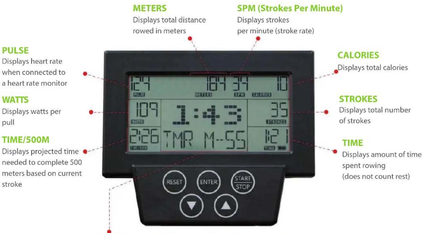
LARGE TOGGLE DISPLAY FOR 9 PERFORMANCE MEASUREMENTS
Track total workout time in minutes and seconds or toggle between 9 different performance measurements to display at the center of the screen:
AVERAGE 500M PACE

Projected time needed to complete 500 meters based on all strokes
AVERAGE METER PER STROKE

Average meters rowed per stroke
MAX HEART RATE CALORIES PER HOUR

Maximum heart rate during workout

Projected calories burned per hour based on all pulls during the workout
FORCE CURVE MAXWATTWATT CHART AVERAGE WATT
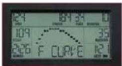
Graphically represents how force is applied during the rowing stroke

Maximum watts produced during all strokes

Graphically represents watts produced relative to other strokes during the workout
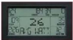
Average watts per stroke based on all strokes
PRE-BUILT PROGRAMS
Toggle through the menu using the up/down arrows to select from the various pre-built programs: Quick Start, Competition Racing, Interval/Tabdata, Target Time, Target Calories, Target Strokes or Target Distance


- Press START to turn on console. You will see "PRESS START TO QUICKSTART OR SELECT PROGRAM" on the meter display
- To choose QUICKSTART, press again and begin your workout.
- To choose a program, press the "UP/ DOWN" key to make your program selection between the following programs:
QUICKSTART / RACE / INTERVAL / TIME / DISTANCE / CUSTOM
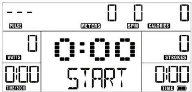
1. QUICKSTART
- The monitor will default to the QUICKSTART mode when you press "START/STOP" or start rowing and do not choose a program.
- During use, the monitor will display the following metrics TIME / STROKES / CALORIES / METERS / WATTS / TIME/500M / PULSE / STROKES PER MINUTE (SPM) Each metric will count up in increments.
- Press the UP / DOWN button to display other metrics such as the TOTAL TIME, AVG / 500M, AVG METER / STROKE, MAX HR, MAX WATT, AVG WATT, CAL / HR, WATT CHART, and FORCE CURVE in the middle window.
- If you stop rowing, the time shown on the lower right window of the monitor will pause. When you start rowing again, it will continue operating from where you left off.
- Press the STOP button to pause the monitor.

1. QUICK - PROGRAM
-
The monitor will default to the QUICKSTART mode when you press "START/STOP" or start rowing and do not choose a program.
-
During use, the monitor will display the following metrics TIME / STROKES / CALORIES / METERS / WATTS / TIME/500M / PULSE / STROKES PER MINUTE (SPM)
-
Press the UP / DOWN button to display other metrics such as the TOTAL TIME, AVG / 500M, AVG METER / STROKE, MAX HR, MAX WATT, AVG WATT, CAL / HR, WATT CHART, and FORCE CURVE in the middle window
-
If you stop rowing, the time shown on the lower right window of the monitor will pause. When you start rowing again, it will continue operating from where you left off.
-
Press the STOP button to pause the monitor.
2. RACE - PROGRAM

-
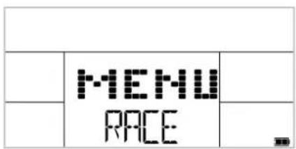
In the start menu, use the "UP / DOWN" key to select RACE, and then press the ENTER key to choose the program
-
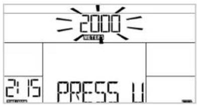
When you select the RACE program, the program defaults to a 2000 meter distance.
-
You can use the "UP / DOWN" button to change the target race distance. Press the ENTER key when finished. Once your target race distance is set, the program defaults to a 2:15 TIME / 500M setting.
-
You can use the "UP / DOWN" button to change the "TIME / 500M" settings. Press the ENTER key when finished.

-
During the RACE program, the following metrics "TIME / STROKES / CALORIES / WATTS /" will count up. The METERS metric will count down to your target race distance.
-
During the race, the dot matrix will show YOUR position and the COMPUTER's position; the monitor will display the meter distance between the two. After the end of the race, the computer will show either the COMPUTER or YOU as the winner.
-
If you stop rowing, the time shown on the lower right window of monitor will pause. When you start rowing again, it will continue operating from where you left off.
-
Press the STOP button to pause the monitor.
3. INTERVAL - PROGRAM
| MENU INTERVAL | ||


-
In the start menu, use the "UP / DOWN" key to select INTERVAL, and then press the ENTER key to choose the program.
-
Note that the program has default settings for the number of intervals, work time, rest time, strokes, calories and meters.
You can change any of the defaults with the directions below. At any time, press START or begin rowing to begin the program with the default settings or mix of your changes and default setting.
-
When the user selects the INTERVAL program, the program defaults to 10 intervals.
-
You can use the "UP / DOWN" button to change the number of intervals. Press the ENTER key when you are finished.
-
Once your number of intervals is set, the program will default to 1:00 of work time.
-
You can use the "UP / DOWN" button to change the amount of work time. Press the ENTER key when you are finished.

-
During the RACE program, the following metrics "TIME / STROKES / CALORIES / WATTS /" will count up. The METERS metric will count down to your target race distance.
-
During the race, the dot matrix will show YOUR position and the COMPUTER's position; the monitor will display the meter distance between the two. After the end of the race, the computer will show either the COMPUTER or YOU as the winner.
-
If you stop rowing, the time shown on the lower right window of monitor will pause. When you start rowing again, it will continue operating from where you left off.
-
Press the STOP button to pause the monitor.
3. INTERVAL - PROGRAM
| MENU INTERVAL | ||


-
In the start menu, use the "UP / DOWN" key to select INTERVAL, and then press the ENTER key to choose the program.
-
Note that the program has default settings for the number of intervals, work time, rest time, strokes, calories and meters.
You can change any of the defaults with the directions below. At any time, press START or begin rowing to begin the program with the default settings or mix of your changes and default setting.
-
When the user selects the INTERVAL program, the program defaults to 10 intervals.
-
You can use the "UP / DOWN" button to change the number of intervals. Press the ENTER key when you are finished.
-
Once your number of intervals is set, the program will default to 1:00 of work time.
-
You can use the "UP / DOWN" button to change the amount of work time. Press the ENTER key when you are finished.
4. TIME - PROGRAM


5. DISTANCE-PROGRAM
| MENU DISTANCE | ||
- In the start menu, use the "UP / DOWN" key to select TIME, and then press the ENTER key to choose the program.
- When you select the TIME program, the program defaults to a time of 20 minutes.
- You can use the "UP / DOWN" button to change the amount of time. Press the ENTER key when finished.
- During the program, the TIME display on the bottom right will count down to 0:00. The STROKES, CALORIES, and METERS metrics will count up.
- Press the UP / DOWN button to display other metrics such as the TOTAL TIME, AVG / 500M, AVG METER / STROKE, MAX HR, MAX WATT, AVG WATT, CAL / HR, WATT CHART, and FORCE CURVE in the middle window.
- If you stop rowing, the time shown on the lower right window of monitor will pause. When you start rowing again, it will continue operating from where you left off.
-
Press the STOP button to pause the monitor.
-
In the start menu, use the "UP / DOWN" key to select DISTANCE, and then press the ENTER key to choose the program.


-
When the user selects DISTANCE program, the program will default to a target distance of 2000 meters.
-
GUsers can use the "UP / DOWN" button to change the target distance. Press the ENTER key when finished.
-
Press START key to begin the program. During the program, the METERS display on the top center will count down to zero. The TIME, STROKES, CALORIES displays will count up.
-
Press the UP / DOWN button to display other metrics such as the TOTAL TIME, AVG / 500M, AVG METER / STROKE, MAX HR, MAX WATT, AVG WATT, CAL / HR, WATT CHART, and FORCE CURVE in the middle window.
-
If you stop rowing, the time shown on the lower right window of monitor will pause. When you start rowing again, it will continue operating from where you left off.
-
Press the STOP button to pause the monitor.
6. CUSTOM - PROGRAM
| MENU CUSTOM | ||
-
In the start menu, use the "UP / DOWN" key to select CUSTOM, and then press the ENTER key to choose the program.
-
Note that the program has default settings for the number of intervals, amount of work time, amount of rest time, strokes, calories, meters. You can change any of the defaults with the directions below. At any time, press START or begin rowing to begin the program with the default settings or mix of your changes and default setting.


| 2000 METERS CALORIES | ||
| PRESS U | 300 STROKES | |
| 20:00 TIME | ||


-
When you select the CUSTOM program, the program defaults to a 20:00 minute default time.
-
Users can use the "UP / DOWN" button to change the amount of time. Press the ENTER key when you are finished.
-
When you select the CUSTOM program, the program defaults to a 20:00 minute default time
-
You can use the "UP / DOWN" button to change the amount of time. Press the ENTER key when you are finished.
-
Once the number of strokes is set, the program will default to 150 calories.
-
You can use the "UP / DOWN" button to change the amount of calories. Press the ENTER key when finished.
-
Once the amount of calories is set, the program will default to 2000 meters.
-
You can use the "UP / DOWN" button to change the amount of meters. Press ENTER key when finished.
-
During the program, the TIME, STROKES, CALORIES, and METERS displays will count down to zero and will stop at zero.
-
Press the UP / DOWN button to display other metrics such as the TOTAL TIME, AVG / 500M, AVG METER / STROKE, MAX HR, MAX WATT, AVG WATT, CAL / HR, WATT CHART, and FORCE CURVE in the middle window.
-
If you stop rowing, the time shown on the lower right window of monitor will pause. When you start rowing again, it will continue operating from where you left off.
-
Press the STOP button to pause the monitor.
INSTRUCTION
- QR code scanner app is required to scan the QR code with an Android or IOS phone or tablet. This app can be downloaded in the App Store or Google Play Store.
- Scan one of the QR codes below to go directly to the place in the App Store or Google Play Store where the app is located and can be downloaded.
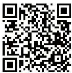
- Scan the QR code on the right to go to the user manual of the app. The manual describes step by step how the app should be connected to the device, how the app works and what the options are.
KINOMAP

APP STORE KINOMAP

GOOGLE PLAY KINOMAP
USER MANUAL KINOMAP

| # DESCRIPTION QTY. | ||
| A1 Main Frame assembly 1 | ||
| A2 Flywheel fan assembly 1 | ||
| A2-1 Fan 1 | ||
| A2-2 Tube 1 | ||
| A2-3 One-way bearing FC2016 1 | ||
| A2-4 Iron washer 1 | ||
| A2-5 S-type buckle S20 2 | ||
| A2-6 Cap head socket screw M5*10 mm 4 | ||
| A2-7 Axial of flywheel Φ20x197 mm | 1 | |
| A2-8 Magnet covering | 1 | |
| A2-9 Ring magnet Φ100*Φ60*15T 1 | ||
| A2-10 Bearing BR-6004ZZDKFL | 2 | |
| A2-12 Tapping screw M4*12 mm | 3 | |
| A2-13 1/4" Chain gear | 1 | |
| A2-14 PU washer | 2 | |
| A2-15 Fan stable bracket Φ430*2.5T | 1 | |
| A2-16 Tapping screw M4*10 mm | 8 | |
| A2-17 R-type buckle R42 | 2 | |
| A3 Chain cover (left) ABS | 1 | |
| A4 'Mesh' | 1 | |
| A5 Chain cover (right) ABS | 1 | |
| A6 Adjust disc ABS | 1 | |
| A7 Tapping screw M4 * 8 mm | 2 | |
| A8 Variable resistor | 1 | |
| A9 Tapping screw M4 x 12 mm | 21 | |
| A10 C-type buckle R40 | 2 | |
| A11 Washer Φ22*Φ44.2*3T | 2 | |
| A12-1 Rubber Cover 6001 | 1 | |
| A12-2 Rubber Cover 6903 | 1 | |
| A13-1 Bearing BR-6001ZZDKFL | 1 | |
| A13-2 Bearing BR-6903ZZDKFL | 1 | |
| # | DESCRIPTION | QTY. |
| A14 | Nylon Insert Lock Nut M10 | 1 |
| A15 | Ring cover ABS | 1 |
| A16 | Sensor Bracket | 1 |
| A17 | Sensor | 1 |
| A18 | Heart rate receiver | 1 |
| A19 | Handle holder ABS | 1 |
| A20 | Philip head socket screw M5*10 mm | 4 |
| A21 | Sensor Base Cover ABS | 1 |
| A22 | Tapping screw M4*12 mm | 5 |
| A23 | Sensor cover ABS | 1 |
| A24 | Outer chain cover ABS | 1 |
| A25 | Handle-bar Φ31.8 | 1 |
| A26 | 1/4" chain | 1 |
| A27 | Chain connecting spacer SC-2473 | 1 |
| A28 | Evan Nut | 2 |
| A29 | Chain hook | 1 |
| A30 | Chain connector | 1 |
| A31 | T-type nut | 2 |
| A32 | Hand grip | 2 |
| A33 | End cap | 2 |
| A34 | Axial of pulley (front) Φ10*79.8 mm | 1 |
| A35 | C-type buckle | 10 |
| A36 | Pulley | 4 |
| A37 | Philip head socket screw M5*10 mm | 4 |
| A38 | Main frame Front cap ABS | 1 |
| A39 | Axial of pulley (back) Φ12.7*76 mm | 2 |
| A40 | Elastic rope bracket | 2 |
| A41 | Chain bracket | 1 |
| A42 | Pulley socket | 1 |
| A43 | Chain pulley | 2 |
| A44 | Hexagon head screw M6*10 mm | 2 |
| # DESCRIPTION QTY. | ||
| A45 Trim panel 2 | ||
| A46 Heaxagon head screw M6*30 mm 1 | ||
| A47 Main frame bottom board (front) 1 | ||
| A48 Main frame bottom board (back) 1 | ||
| A49 Axial of pin Φ12.7*76 mm 1 | ||
| A50 Spring 1 | ||
| A51 Nut 1 | ||
| A52 Plug block 1 | ||
| A53 Foot pad 1 | ||
| A54 Washer M4*Φ10*1T 2 | ||
| A55 Tapping screw M4*10 mm | 2 | |
| A56 Swivel axial | 1 | |
| A57 Swivel axial socket Φ21.5*12 mm | 2 | |
| A58 Washer 1/2*2.0T*Φ23 | 2 | |
| A59 Cap head socket screw M10*16 mm | 2 | |
| A60 Chain connecting axial | 1 | |
| A61 Elastic rope | 1 | |
| A62 Axial of moving wheel Φ8*156 mm | 1 | |
| B1 | Aluminum rail | 1 |
| B2 | Seat carriage roller cover | 2 |
| B3 | Seat carriage cover | 2 |
| B4 | Seat carriage wheel | 4 |
| B5 | Bearing PR-608ZZ(BMC) | 8 |
| B6 | Spacer Φ8*Φ12*2 mm | 8 |
| B7 | Seat carriage axial Φ10*121 mm | 2 |
| B8 | Washer M8*2.0T*Φ16 | 4 |
| B9 | Lower acorn Nut M8 | 4 |
| B10 | Seat carriage roller | 2 |
| B11 | Bearing PR-608ZZ(BMC) | 2 |
| B12 | Even head socket screw M8*20 mm | 2 |
| # | DESCRIPTION | QTY |
| B13 Washer M8*Φ16*2T | 2 | |
| B14 Lower acorn nut M8 | 2 | |
| B15 Rail upper plate | 1 | |
| B16 Cap head socket screw M6*10 mm | 2 | |
| B17 Rail end cap ABS | 1 | |
| B18 Philip head socket screw M5*10 mm | 4 | |
| B19 Double head screw Φ5.25*85 mm | 1 | |
| B20 Seat carriage stopper TPR | 2 | |
| B21 Rail handle | 1 | |
| C1 | Front stabilizer | 1 |
| C2 | Flat oval cap 40*80 | 2 |
| C3 | Moving wheel Φ50 | 4 |
| C4 | Philip head socket screw M8*40 mm | 2 |
| C5 | Lower acorn nut M8 | 4 |
| C6 | Foot pad | 2 |
| C7 | Tapping screw M4*12 mm | 2 |
| D1 | Rear stabilizer | 1 |
| D2 | Flat oval cap 40*80 | 2 |
| D3 | Foot pad 40*32 | 2 |
| D4 | Tapping screw M4*12 mm | 2 |
| E1 | Left pedal rest | 1 |
| E2 | Right pedal rest | 1 |
| E3 | Adjust pedal pad TPE | 2 |
| E4 | Left pedal rest cover | 1 |
| E5 | Right pedal rest cover | 1 |
| E6 | Tapping screw M4*8 mm | 8 |
| E7 | Set piece | 2 |
| E8 | Set base | 2 |
DESCRIPTION QTY.
| E9 Foot snap 2 | ||
| E10 Flat head philips screw M5*15 mm 4 | ||
| E11 Flat head philips screw M4*15 mm 2 | ||
| E12 Spacer 2 | ||
| E13 Nylon isert lock nut M4 2 | ||
| E14 Foot strap 2 | ||
| F Seat 1 | ||
| G1 | Console tube | 1 |
| G2 | Console bracket | 1 |
| G3 | Console back cover (old design) | 1 |
| G4 | Cap head socket screw M8*85 | 1 |
| G5 | Nylon acorn nut M8 | 1 |
| G6 | Console | 1 |
| G7 | Ball head screw M5*10 mm | 4 |
| H1 | Left display tube cover ABS | 1 |
| H2 | Right display tube cover ABS | 1 |
| J0 | Nylon insert lock nut M8 | 2 |
| J1 | Cap head socket screw M10*16 mm | 4 |
| J2 | Washer M10*1.5T*Φ20 | 4 |
| J3 | Cap head socket screw M6*50 mm | 4 |
| J4 | Tapping screw M4*12 mm | 3 |
| J5 | Cap head socket screw M8*35 mm | 2 |
| J6 | Cap head socket screw M8*16 mm | 10 |
| J7 | Washer M8*Φ16*1.5T | 10 |
| J8 | Pull pin | 1 |
| J9 | Ball head view M4*10 mm | 2 |
| J10 | Spring washers | 2 |
| K | Pedal stable bracket | 1 |
virtufit
For questions or missing parts please contact your dealer.

- User manual
- WARNING:
- ATTENTION
- Warranty claim is excluded if the cause of the defect is the result of:
- TOOLKIT
- STEP 1
- STEP 2
- STEP 3
- STEP 4
- STEP 5
- STEP 6
- STEP 7
- Rower storage
- CONSOLE ROWING MACHINE
- PRE-BUILT PROGRAMS
- QUICKSTART
- QUICK - PROGRAM
- RACE - PROGRAM
- INTERVAL - PROGRAM
- TIME - PROGRAM
- DISTANCE-PROGRAM
- CUSTOM - PROGRAM
- INSTRUCTION
- DESCRIPTION QTY.
- virtufit
Brand : VirtuFit
Model : Ultimate Pro 2i
Category : Rowing Machine