
Elite Water Resistance - Rowing Machine VirtuFit - Free user manual and instructions
Find the device manual for free Elite Water Resistance VirtuFit in PDF.

| Product Type | Water Resistance Rowing Machine |
| Brand | VirtuFit |
| Model | Elite Water Resistance |
| Maximum User Weight | 200 kg |
| Usage | Domestic |
| Resistance | Water (water tank with purification tablet) |
| Console Display | Time, distance, calories, heart rate, SPM (strokes per minute), stroke count, watts |
| Training Programs | Manual, Interval (10/20, 20/10, custom), Goal (time, distance, calories, strokes, pulse) |
| Connectivity | Bluetooth, compatible with Kinomap and FitShow apps |
| Console Power Supply | Mains (power cable) |
| Dimensions (approx.) | Not specified in the manual |
| Device Weight | Not specified in the manual |
| Mounting Surface | Solid and flat; avoid thick carpets |
| Operating Temperature | 10 °C to 35 °C |
| Storage Temperature | 5 °C to 45 °C |
| Routine Maintenance | Clean after each use; annual lubrication of moving parts (non-acidic vaseline or silicone spray) |
| Semi-annual Maintenance | Check and tighten bolts/nuts; check mobility of parts |
| Cleaning | Regular dusting; no harsh chemicals |
| Safety | Consult a doctor before use; wear sports shoes; keep children and animals away; stop if unwell |
| Warranty | Excluded if unauthorized repair, improper use, or lack of maintenance |
| Spare Parts | Manual water pump, funnel, reservoir cap, water purification tablets |
| Repairability | Repairs by professional technician only |
Frequently Asked Questions - Elite Water Resistance VirtuFit
User questions about Elite Water Resistance VirtuFit
0 question about this device. Answer the ones you know or ask your own.
Ask a new question about this device
Download the instructions for your Rowing Machine in PDF format for free! Find your manual Elite Water Resistance - VirtuFit and take your electronic device back in hand. On this page are published all the documents necessary for the use of your device. Elite Water Resistance by VirtuFit.
USER MANUAL Elite Water Resistance VirtuFit
natural_image
Technical line drawing of a mechanical device with no visible text or symbolsA
natural_image
Simple line drawings of a microphone and a funnel with labeled green circles (C and D) — no text or symbols present.D

●

natural_image
Technical line drawing of a mechanical component with two symmetrical slots and a central handle (no text or symbols)B
E

natural_image
Simple line drawing of a desk lamp and a holder with green circular elements (no text or symbols)●
natural_image
Simple line drawing of a long cylindrical object with a small protrusion and a green circular icon labeled 'K' in the corner (no text or symbols on the object itself)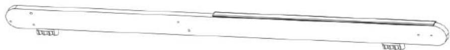
natural_image
Simple line drawing of a cylindrical object with a horizontal bar and label 'HPL' (no text or symbols on the object itself)L
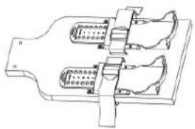
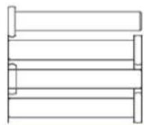
DESCRIPTION QTY
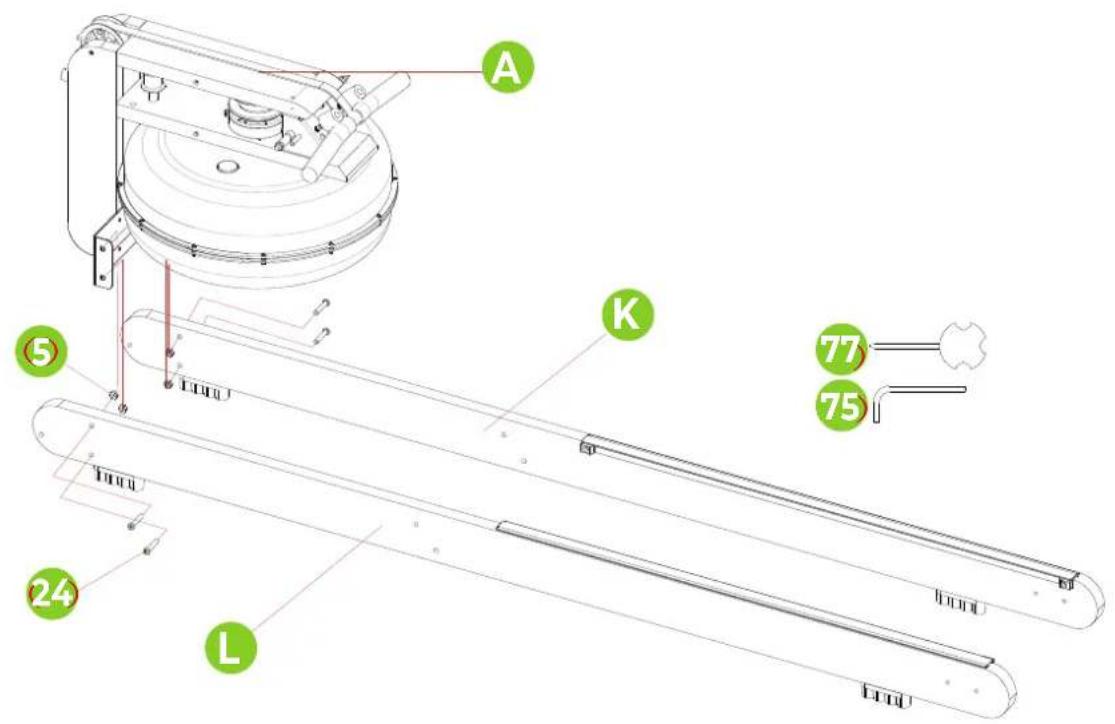
| A Rowing machine 1 | |
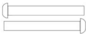
| B Pedal 1 | |
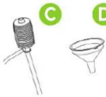
| C Hand pump 1 | |
| D Funnel 1 | |
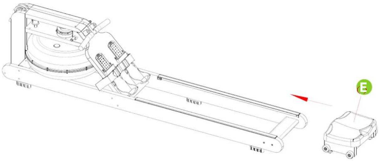
| E Cushion 1 | |
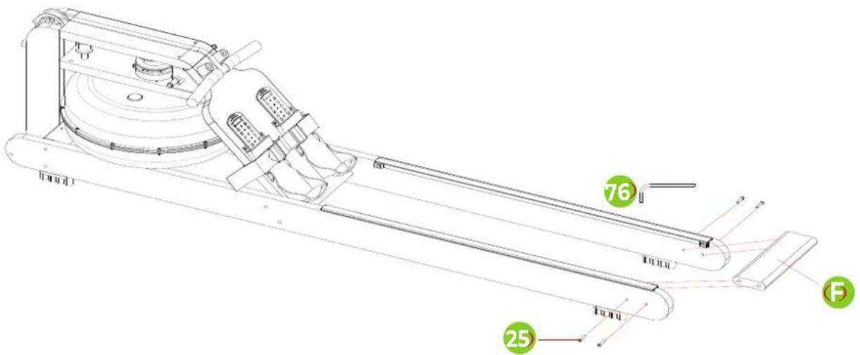
| F Rear connecting plate 1 |
DESCRIPTION QTY
| G iPad holder | 1 | |
| H PU roller | 1 | |
| I | Console | 1 |
| J | Accessories package | 1 |
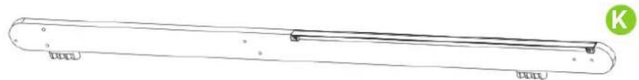
| K Right track assembly | 1 | |
| L Left track assembly | 1 | |
NOTE! Do not connect the unit to the power supply until it is fully assembled.
LET OP! Sluit het toestel pas aan op het stroom wanneer het volledig is gemonteerd.
HINWEIS! Schließen Sie das Gerät erst dann an das Stromnetz an, wenn es vollständig montiert ist.
REMARQUE! Ne connectez pas l'appareil à l'alimentation électrique avant qu'il ne soit entièrement assemblé.
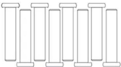
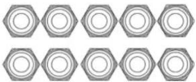
HARDWARE KIT
natural_image
Pure line drawing of eight identical cylindrical objects with no text or symbols(24) SCREW MB*40 - 8PCS
natural_image
Repeating pattern of hexagonal shapes with no text or symbols(5) NUT M8 - 10PCS
(25) SCREW M6*40 - 4PCS
natural_image
Two horizontal cylindrical objects with curved ends, no text or symbols present(2) SCREW M8*65 - 2PCS

(7) WASHER D8*016*1.5 - 6PCS
STEP 01
STEP 02
STEP 03
STEP 04
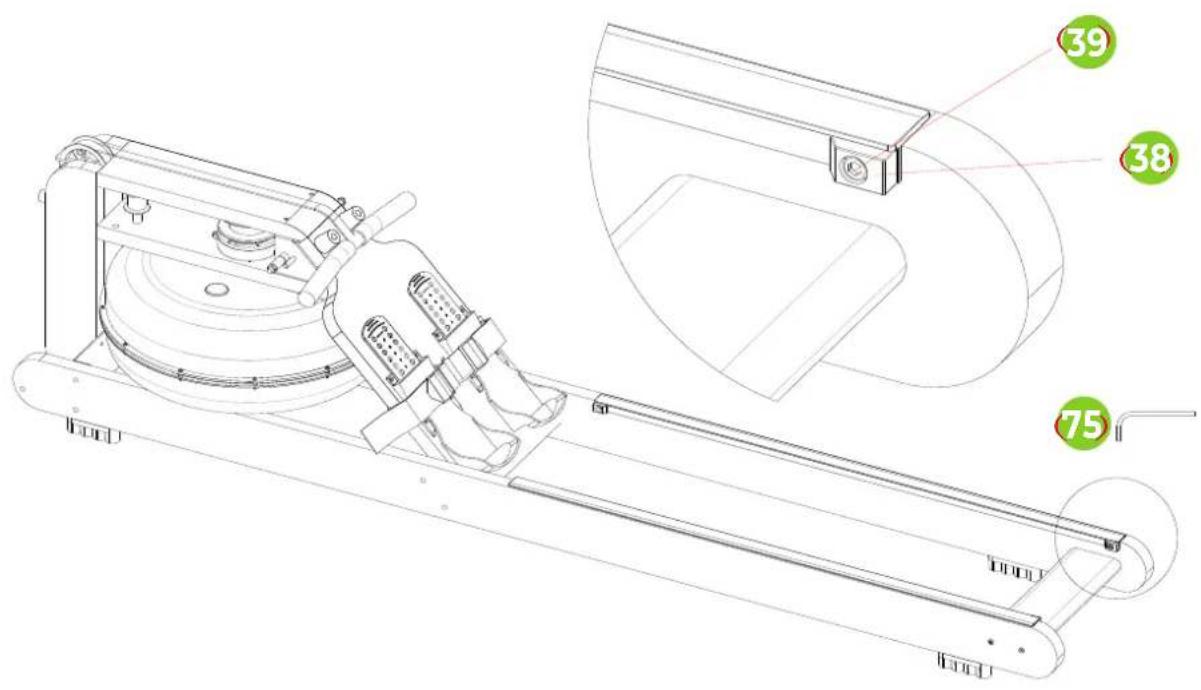
STEP 05
STEP 06
STEP 07
STEP 10
natural_image
Technical line drawing of a mechanical assembly with a circular cross-section and a 3D schematic view showing internal components (no text or symbols)STEP 11
STEP 12
natural_image
Technical line drawing of a mechanical device with two views: top shows internal components, bottom shows close-up of a circular component (no text or symbols)STEP 13
natural_image
Technical line drawing of a stationary exercise machine with wheels and control panel (no text or symbols)STEP 14
natural_image
Technical line drawing of a mechanical device with labeled parts (no text or symbols present)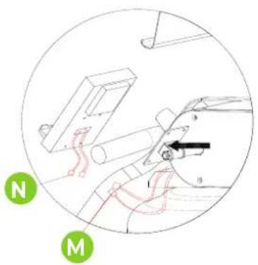
FIG. 15, A-S
A

natural_image
Solid teal background with horizontal black lines and a small black square in the center (no text or symbols)B

natural_image
Simple geometric pattern with horizontal lines and a small black rectangle on the left (no text or symbols)C

natural_image
Solid teal-colored background with horizontal black lines and a small black square at the bottom (no text or symbols)D

natural_image
Solid teal background with horizontal black lines and a small dark rectangle in the center (no text or symbols)E

natural_image
Solid teal background with horizontal black lines and a small black square at the bottom (no text or symbols)F

natural_image
Simple geometric diagram with horizontal lines and two black rectangles at the bottom (no text or symbols)G

H
1

J

K

L

M

N

natural_image
Solid teal background with horizontal black lines and a small black square in the top-left corner (no text or symbols)0

natural_image
Simple geometric diagram with horizontal lines and a small black rectangle on the top (no text or symbols)p

natural_image
Solid teal-colored background with horizontal black lines and a small black square in the center (no text or symbols)q

natural_image
Solid teal-colored background with horizontal black lines and a small black square at bottom (no text or symbols)R

s
FIG. 16, A-E
natural_image
Line drawing of a person bending forward with hands raised (no text or symbols)A

natural_image
Line drawing of a person sitting cross-legged, holding their head in thought (no text or symbols)B
natural_image
Line drawing of a person performing a seated stretch or exercise (no text or symbols)C

natural_image
Line drawing of a person in athletic attire performing a forward bend gesture (no text or symbols)D
natural_image
Line drawing of a person performing a stretching exercise with arms raised (no text or symbols)E
INDEX
| Safety instructions | 13 | |
| Guarantee | 13 | |
| Assembly instructions 13 | ||
| Moving and adjusting 14 | ||
| Filling and emtying the water tank 14 | ||
| Training with fitness apps 14 | ||
| Maintenance | 15 | |
| Console | 15 | |
| Programs | 16 | |
| Training guidelines | 17 | |
SAFETY INSTRUCTIONS

WARNING
Consult your doctor before you start exercising. This is particularly important for people with health problems. Please read all instructions before using the machine. VirtuFit assumes no responsibility for injury or property damage resulting from the use of this equipment. Please read this manual carefully before assembling and/or using the machine.
• Make sure that the machine is properly assembled and that all nuts and bolts are tight before using it.
• Assemble the machine with at least two people.
- Lubricate all moving parts annually with petroleum jelly (acid-free) or silicone spray.
- Do not wear loose clothing to avoid getting caught in moving parts.
• Install and use the unit on a solid, level surface.
• Always wear clean sports shoes when using the appliance.
- Keep children and pets away from the appliance when in use.
- Maintain your balance when using the device.
- Do not place your fingers or other objects in the moving parts.
- Before exercising, consult your physician to determine the appropriate frequency, duration and intensity of exercise for your age and physical condition. Stop exercising immediately if you experience nausea, shortness of breath, fainting, headache,
chest pain, tightness or any other discomfort.
- Do not hold the machine by the seat when moving.
• This machine should only be used by one person at a time. - This machine is designed for domestic use and the maximum user weight is 200 kg.
- Leave 1-2 metres of space behind the machine to avoid accidents.
- Place the machine on a clean, flat surface. Do not place it on a thick carpet, as this may hinder the ventilation of the machine. Do not place the machine outdoors or near water.
- Keep the storage area dry, clean and level to prevent damage. Do not use the device for any purpose other than training.
- Use the device only in an environment where the ambient temperature is between 10°C and 35°C. Store the device only in an environment where the temperature is between 5°C and 45°C.
GUARANTEE
Warranty claims are excluded if the cause of the defect is the result of:
- Maintenance and repair work not carried out by an official dealer.
- Improper use, negligence and/or poor maintenance.
- Failure to maintain the appliance in accordance with the manufacturer's instructions.
ASSEMBLY INSTRUCTIONS (STEP 01-14)
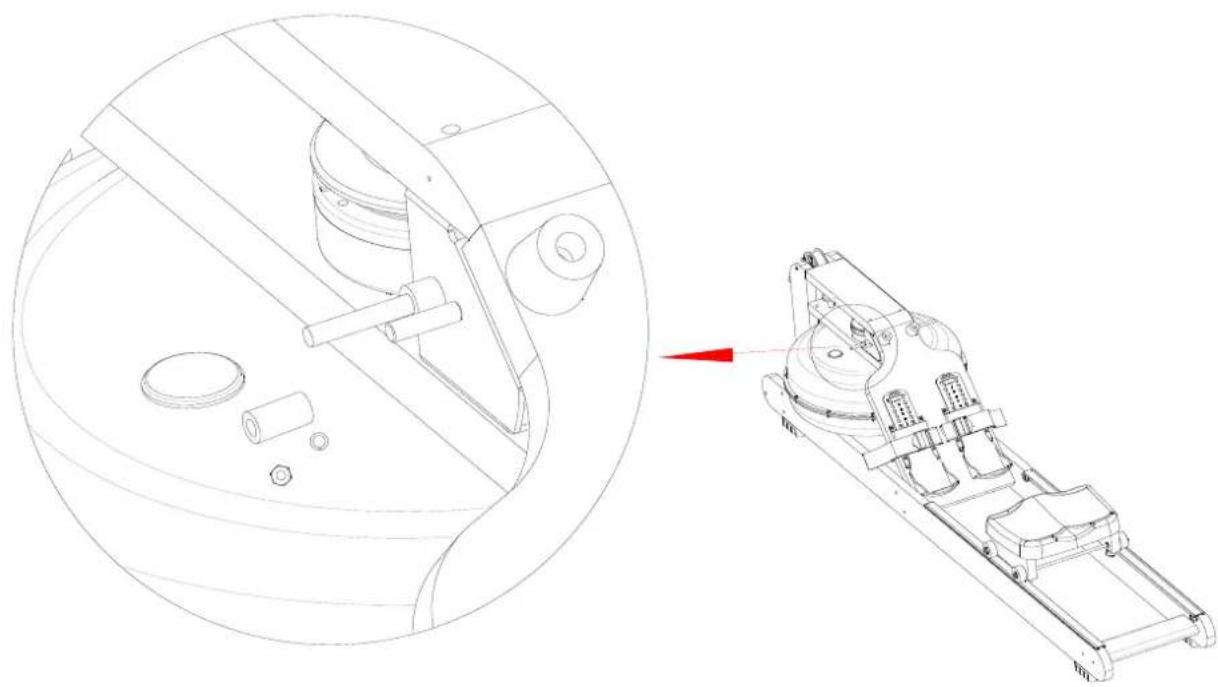
Missing parts: If any parts are missing from the packaging, carefully check the polystyrene foam and the appliance itself. Some parts (bolts, screws, etc.) are already attached to the unit.
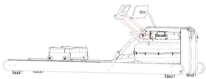
Error message: Make sure that all cables are carefully attached. The aluminium feet of the console are very sensitive and must be kept straight. If the console gives an error message after the machine has been mounted, the aluminium feet of the console may be bent. Straightening the aluminium feet may make the error message disappear.
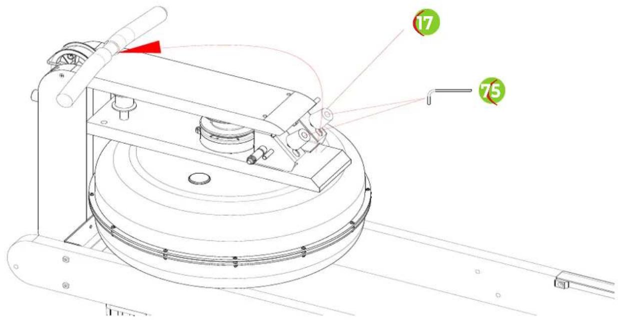
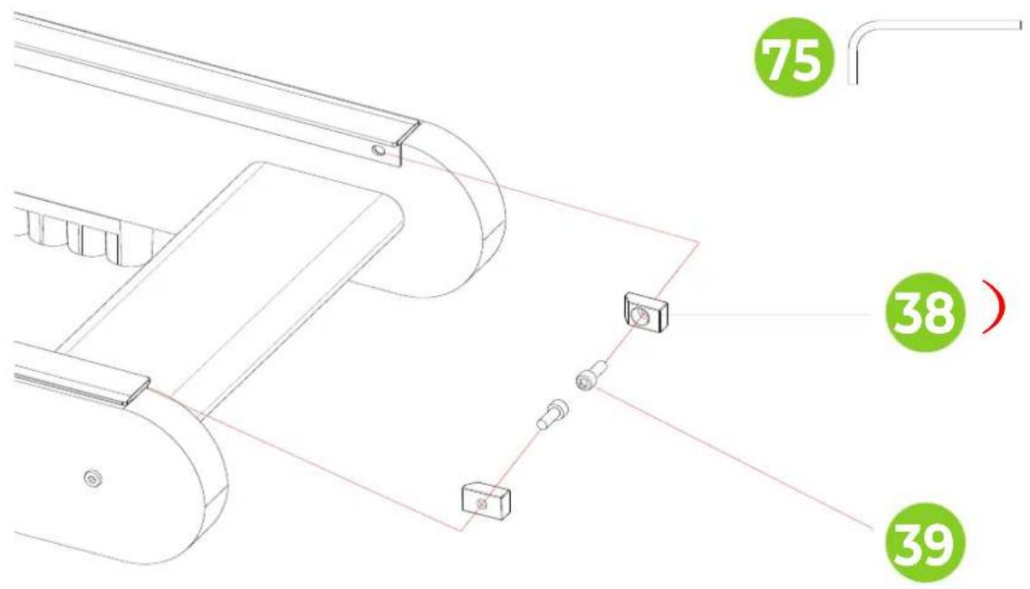
Hex head bolts: Make sure that the hex head spanner is pushed into
the bolt before applying force. This will prevent the head of the socket bolt from turning.
MOVING AND ADJUSTING
Moving
CAUTION! Store the tool in a dry place, out of the reach of children. Make sure that the tool is stable and safe so that it cannot fall on children or animals.
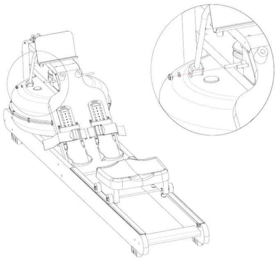
Raise the rear stabiliser until the front stabiliser wheels touch the ground. With the wheels on the ground, the machine can easily be moved to the desired location. NOTE: The seat slides when the machine is in the upright position.
NOTE! The seat slides when the machine is in the upright position.
Adjusting the pedal
The pedal strap is adjustable and can be adjusted to the size of the user's foot.
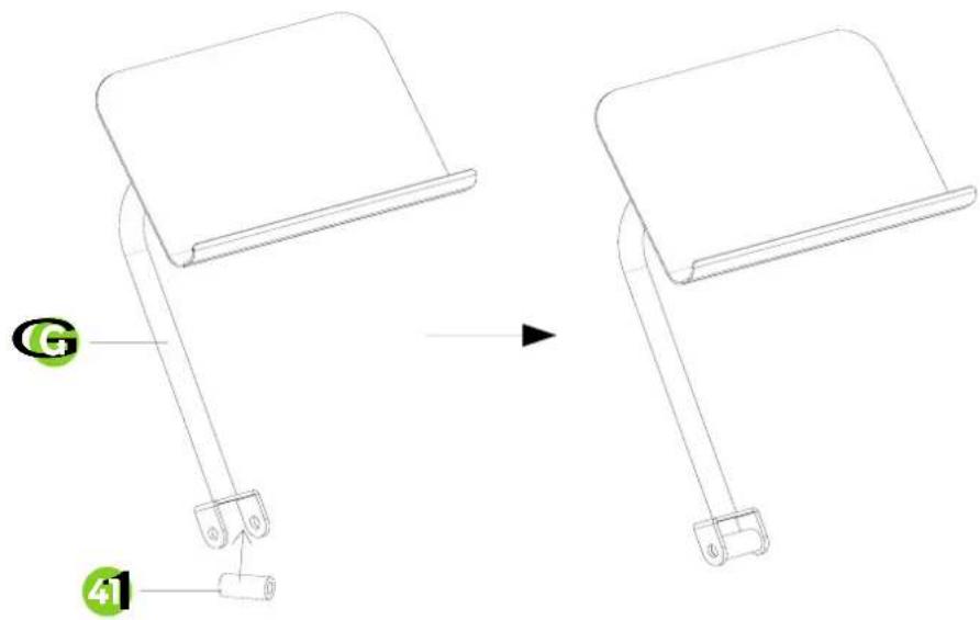
Shelf support adjustment
The shelf support is adjustable so that you can always train in the best position.
FILLING AND EMPTYING THE WATER TANK
CAUTION!
· Always fill the tank with tap water only and add a water purification tablet. Never use chlorinated water or chlorine. This can damage the tank and void the warranty.
- Add a water purification tablet once every six months. If the water remains cloudy, replace the water in the tank.
- The water in the tank is not consumable. Discard the water after it has been pumped out of the tank.
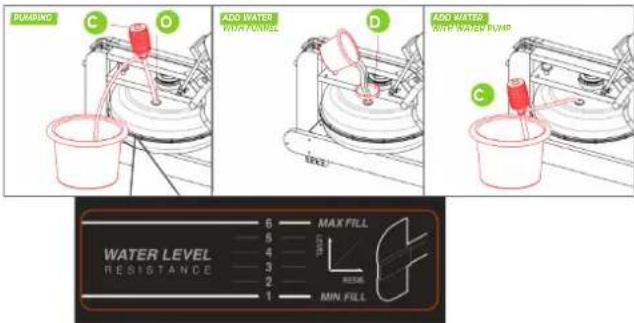
Filling the water tank
- Remove the water tank cap (O) from the top water tank opening. The water tank can be filled in two ways.
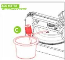
- Manual water pump (C): Insert the hose end of the manual water pump (C) into the bucket filled with water and insert the other end of the hose into the water tank opening. Press the hand water pump to fill the water tank.
- Funnel (D): Insert the funnel (D) into the opening of the water tank and pour a bucket full of water through the funnel into the water tank.
- Look at the side of the water tank to see what the water level is in the tank.
- Replace the water tank closing cap (O) on the opening of the water tank, so that it is properly closed.
Empty the water tank
- Remove the water tank closure cap (O) from the top water tank opening.
- Place an empty bucket next to the water tank and insert the end of the manual water pump hose (C) into the empty bucket. Insert the other end of the hose into the opening of the water tank. Squeeze the hand water pump to empty the water tank.
- When the water tank is empty, dry it with a cloth.
- Replace the water tank cap (O) on the water tank opening so that it is properly sealed.
TRAINING WITH FITNESS APPLICATIONS
VirtuFit does not provide service for third party fitness applications such as Kinomap, iConsole, FitShow etc. If you encounter problems with a third party fitness application, please contact the developer of the application in question.
Instruction
- To scan the QR code with an Android or IOS phone or tablet, a QR code scanner is required. The app for scanning QR codes can be downloaded from the App Store or Google Play Store.
- Scan one of the QR codes below to go directly to the App Store or Google Play Store page where the fitness app can be downloaded.
- Scan the QR code on the right to access the fitness app manual. The manual describes step by step how to connect the fitness app to the device, how the fitness app works and what its capabilities are.
Fitshow

APP STORE

GOOGLE PLAY MANUAL

Kinomap

APP STORE

GOOGLE PLAY MANUAL

MAINTENANCE
Safe and efficient use can only be achieved if the appliance is properly installed and maintained. It is your responsibility to ensure that the appliance is maintained regularly. Parts that have been used and/or damaged must be replaced before the appliance is used again. The appliance should only be used and stored indoors. Long-term exposure to weather and temperature/humidity changes can have a serious impact on the electrical components and moving parts of the unit. Always unplug the power cord from the unit before cleaning or servicing it.
Daily maintenance
- Clean and remove sweat and moisture after each use.
- Check that the unit is free of dust and dirt.
- Do not use aggressive cleaning agents and keep the device away from moisture.
Semi-annual maintenance
- Clean and remove sweat and moisture after each use.
- Check that the unit is free of dust and dirt.
- Do not use aggressive cleaning agents and keep the device away from moisture.
CAUTION!
- All repairs must be performed by a professional technician, unless otherwise specified by the supplier or manufacturer.
Cleaning
General cleaning of the machine will prolong its life. Keep the machine clean by dusting it regularly.
Regular maintenance extends the life of your machine and prevents accidents! For more information, please visit https://www.virtufit.nl/service/faq/
CAUTION! Wear clean shoes to reduce the risk of soiling the machine.
CONSOLE

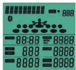
- START/STOP Start/stop.
- MODE Confirm the setting.
- RESET Press "RESET" to return to the main screen. Press and hold to reset.
- UP Increase the setting.
- RECOVERY Heart rate recovery test.
- INTERVAL CUSTOM Interval training setting.
- BLUETOOTH Bluetooth function on/off.
Functions
• TIME The total rowing time from the beginning to the end of the exercise is displayed.
- DISTANCE The distance of each workout is displayed when you start the workout
- PULSE The current heart rate will be displayed if it is detected during the workout.
- CALORIE The total number of calories from start to finish of the workout is displayed.
- SPM Beat rate:The total number of calories from start to finish of the workout is displayed.
- STROKES Number of strokes during exercise.
• WATT Displays the number of workout watts.
NOTE! If there is no movement for more than 4 minutes, the console will automatically turn off.
PROGRAMS (FIG. 15, A-S)
Powering up and sleep mode
POWER ON After powering up the console (or by pressing Mode/Reset for 3 seconds), it will beep for 2 seconds and the LCD screen will be displayed in full for 2 seconds, then enter standby mode.
STANDBY MODE After powering up, the console goes into standby mode. MANUAL - INTERVAL - TARGET - TIME - DISTANCE - CALORIE - PULSE - SPM - STROKES - SCAN are displayed in sequence for 1 second (Fig. 16-B to 16-H, page 18).
NOTE! If there is no movement for more than 4 minutes, the console will automatically go into sleep mode.
Manual Mode
- If an RPM signal is heard during standby, immediately start the QUICK START function and the signal will sound for 1 second.
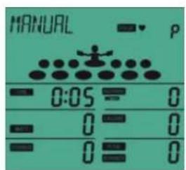
- Or, in standby mode, press the MODE button and the console will display MANUAL. Press the MODE button, the beeper will sound for 1 second and the MANUAL function will start (Fig. 16-I, page 18). The LCD display will constantly show MANUAL. TIME - DISTANCE - CALORIES - PULSE - SPM - WATCH - RACE start counting and are displayed according to the calculated values.
- During the exercise, press the START/STOP button until STOP flashes. TIME - DISTANCE - TOTAL STROKES - CALORIES always
shows the current training value and PULSE shows the heart rate value in real time.
- When the STOP button is displayed on the console, press the START/STOP button. The console will continue to run the workout. If you press the RESET button while in stop mode, the console will return to standby mode. If there is no activity for more than 4 minutes, the console will automatically go into sleep mode.
INTERVAL
In standby mode, press the MODE button and the UP button to activate and select the INTERVAL function. The console displays INTERVAL flashing (Fig. 16-J to 16-M).
INTERVAL 10/20 INTERVAL flashes on the console. Press the MODE button and select the 20/10 function. The console flashes 10/20, press the START/STOP BUTTON to start the 10/20 function.
INTERVAL 20/10 INTERVAL flashes on the console, press the MODE button and select the 20/10 function by pressing the UP button. The console flashes 20/10, press the START/STOP button to start the 20/10 function.
INTERVAL CUSTOM The console flashes INTERVAL, press the MODE button and select the CUSTOM mode by pressing the UP button. The console flashes CUSTOM, press the START/STOP BUTTON to start the CUSTOM mode.
Target
In Standby mode, press the MODE button, then press the UP button to select TARGET, the console will display TARGET flashing (Fig. 16-N to 16-T).
TARGET TIME (Fig. 16-0) Press the MODE button while TARGET is flashing on the console, then switch to the device display. Press SET to access the TARGET TIME function. The console will still display TARGET and TIME will flash. Press the MODE button to enter the TIME setting mode.
TARGET DISTANCE (Fig. 16-P) With TARGET flashing on the console, press MODE to select TARGET DISTANCE. Press UP to enter the TARGET DISTANCE function. The console will still display TARGET, with DISTANCE flashing in the window. Press the MODE button to start the DISTANCE function.
TARGET CALORIES (Fig. 16-Q) Press the MODE button while TARGET is flashing on the console, select the TARGET CALORIES function by pressing UP. The console will still display TARGET and the CALORIES window will flash. Press the MODE button to start the CALORIES function.
TARGET STROKES (Fig. 16-R) Press MODE while TARGET is flashing on the console, select the TARGET STROKES function by pressing UP. The console will still display TARGET, with STROKES flashing in the window. Press the MODE button to start the STROKES function.
TARGET PULSE (Fig. 16-S) Press the MODE button while TARGET is flashing on the console, select the TARGET PULSE function by pressing UP. The console will always display TARGET, with PULSE flashing in the window. Press the MODE button to start the PULSE function.
TRAINING GUIDELINES (FIG. 16, A-E)
A successful training program includes a warm-up, the actual training and a cool-down. Perform the complete training program at least twice, but preferably three times a week and keep a rest day between training sessions. After a few months, the intensity of the training can be increased, for example to four or five times a week.
The warm-up
The purpose of a warm-up is to prepare the body for training and to reduce the risk of injury. Warm up your body for two to five minutes before starting a cardio or strength training session. Do exercises that increase the heart rate and warm up the working muscles. Examples of this type of activity are running, jogging, jumping jacks, skipping and running in place.
Stretching
Stretching while the muscles are warm is very important after a good warm-up and cool-down. It reduces the risk of injury. Stretching exercises should be held for 15-30 seconds. Here are some examples of stretching exercises:
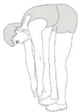
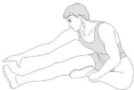
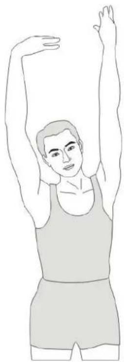
- Toe touch (Fig. 16-A)
• Inner thight stretch (Fig. 16-B) - Hamstring stretch (Fig. 16-C)
• Achilles stretch (Fig. 16-D) - Side stretch (Fig. 16-E)
Cooling down
The purpose of the cool-down is to return the body to its (near) normal resting position at the end of the workout. A good cool-down slowly reduces your heart rate and promotes recovery.
INHOUD

Watertank vullen
PROGRAMMA'S (FIG. 15, A-S)
Inschakelen en standby-modus

PROGRAMME (FIG. 15, A-S)

PROGRAMMES (FIG. 15, A-S)
DESCRIPTION QTY.
| 1 PVC sleeve PVC/φ15*φ8.2*12 5 | ||
| 2 Small roller φ28*11.5 4 | ||
| 3 Hexagon bolt M8×110×20×S14 4 | ||
| 4 Cushion mounting plate 220*73*27 2 | ||
| 5 Nylon nut M8xH7.5xS14 17 | ||
| 6 Seat cushion roller φ46*22 4 | ||
| 7 Flat washer d8×Φ16×1.5 26 | ||
| 8 Seat cushion 1 | ||
| 9 Shaft with retaining ring D8×0.8 | 4 | |
| 10 | Seat roller shaft Q235/φ8*363 | 4 |
| 11 | Cross groove pan-head self-tapping screw ST4.2x16xΦ7 | 20 |
| 12 | Foot bottom 132*106*18 | 2 |
| 13 | Adjustable pedal 343*106*56 | 2 |
| 14 | The pedals 550*300*27 | 1 |
| 15 | Front connecting board assembly 303*100*40*δ2.5 | 1 |
| 16 | Hexagon head wood screw M6×25×S10 | 7 |
| 17 | Handle rubber pad 33*27*33 | 2 |
| 18 | Hexagonal cylindrical head screws M6*40×S4 | 2 |
| 19 | PVC grip sleeve | 2 |
| 20 | Handgrip φ25*δ1.5 | 1 |
| 21 | Hexagonal pan-head screws M8×65×20×S5 | 2 |
| 22 | PU roller φ69*23.5 | 2 |
| 23 | IPAD support assembly | 1 |
| 24 | Inner hexagonal flat head screw M8×40×15×S5 | 8 |
| 25 | Inner hexagonal flat head screw M6×40×S4 | 4 |
| 26 | Foot pad 100*25*25 | 4 |
| 27 | Hexagonal pan-head screws M8×25×S5 | 4 |
| 28 | Gasket d8×Φ16×1.5 | 1 |
| 29 | Cushion | 2 |
| 30 | Hexagonal cylindrical head screws M6*70 | 4 |
| 31 | Block and tackle | 1 |
| 32 | Front connection board 303*100*40*δ2.5 | 1 |
| 33 | Induction line holder | 1 |
| 34 | Straps | 2 |
| 35 | Left slide rail 2116*103*27 | 1 |
| 36 | Right slide rail 2116*103*27 | 1 |
| 37 | Regula 30*17.5*1027 2 | |
| 38 | Seat cushion block 25*15*10 | 4 |
DESCRIPTION QTY.
| 39 | Hexagonal cylindrical head screws M6×16×S5 | 4 |
| 40 | M6 cylindrical nut φ10*20 | 4 |
| 41 | PVC sleeve φ16*φ10.2*28 | 5 |
| 42 | Roller φ51*φ38*32 | 1 |
| 43 | Belt roller axle φ10*106 | 1 |
| 44 | PVC sleeve φ16*φ10.2*17 | 1 |
| 45 | Top connection board 406.5*124*27 1 | |
| 46 | Console | 1 |
| 47 | Shaft sleeve φ25*φ17.2*15 | 1 |
| 48 | Inner hexagonal flat head screw M6*30×S4 | 2 |
| 49 | Console support bracket | 1 |
| 50 | Drawback assembly | 1 |
| 51 | Cross groove pan-head screw M3×20xΦ6 | 12 |
| 52 | PVC sleeve PVC/φ15*φ8.2*50 | 1 |
| 53 | Hexagonal pan-head screws M8*100 | 1 |
| 54 | Right fixed connection assembly | 1 |
| 55 | Left fixed connection assembly | 1 |
| 56 | Plastic bearing base | 1 |
| 57 | Rubber gasket ∅50*6 | 2 |
| 58 | Rubber washer | 1 |
| 59 | Fixing pin SUS304/ø8*40 | 1 |
| 60 | Hexagonal pan-head screws M8×20×S5 | 1 |
| 61 | Tank mouth plug A-φ30.5 | 1 |
| 62 | Water tank upper cover φ518*100 | 1 |
| 63 | Paddle blade φ462*124 | 1 |
| 64 | Water tank sealing ring φ501*7 | 1 |
| 65 | Water tank lower cover φ518*100 | 1 |
| 66 | Nylon nut M3xH3.8xS6 | 12 |
| 67 | Hand pump PE/570 1 | |
| 68 | Funnel | 1 |
| 69 | Connection board 303*107*27 1 | |
| 70 | Water tank fixing board 479.8*124*27 | 1 |
| 71 | Left upright board 436.5*103*27 | 1 |
| 72 | Right upright board 436.5*103*27 | 1 |
| 73 | Hexagonal pan-head screws M8*80 | 2 |
| 74 | IPAD assembly | 1 |
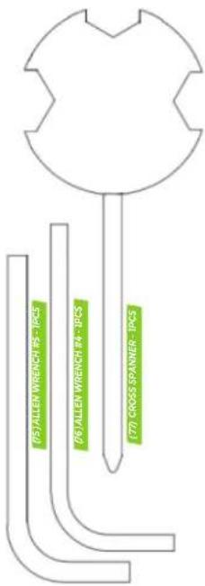
| 75 | Allen wrench #5 | 1 |
| 76 | Allen wrench #4 | 1 |
PARTS LIST
virtufit
DESCRIPTION QTY.
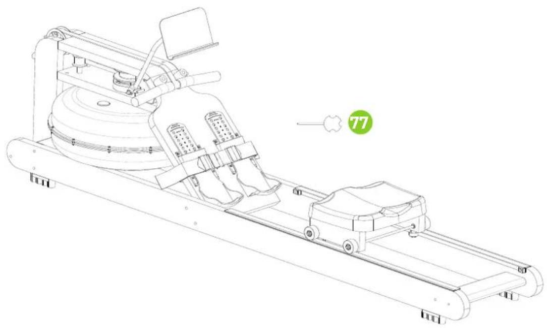
| 77 Cross spanner 1 | |
| 78 Elastic pad D8 2 |
virtufit
COMPANY INFORMATION
For an ongoing service request or to purchase parts, please visit; service@virtufit.nl. Always state the service number (ITS number) with a question about the current application for a quick and efficient settlement. A service request must always be submitted via the service form. So the request not to request service via info@virtufit.nl.
Do you have a problem with your VirtuFit fitness equipment and would you like to submit a service request? Then scan the QR code on the right and fill in our service form.

VIRTUFIT
Twekkelerweg 263
7553 LZ Hengelo
The Netherlands
info@virtufit.nl

- DESCRIPTION QTY
- SAFETY INSTRUCTIONS
- WARNING
- GUARANTEE
- ASSEMBLY INSTRUCTIONS (STEP 01-14)
- MOVING AND ADJUSTING
- Moving
- Adjusting the pedal
- Shelf support adjustment
- FILLING AND EMPTYING THE WATER TANK
- CAUTION!
- Filling the water tank
- Empty the water tank
- TRAINING WITH FITNESS APPLICATIONS
- Instruction
- MAINTENANCE
- Daily maintenance
- Semi-annual maintenance
- Cleaning
- Functions
- PROGRAMS (FIG. 15, A-S)
- Powering up and sleep mode
- Manual Mode
- INTERVAL
- Target
- TRAINING GUIDELINES (FIG. 16, A-E)
- The warm-up
- Stretching
- Cooling down
- INHOUD
- Watertank vullen
- PROGRAMMA'S (FIG. 15, A-S)
- PROGRAMME (FIG. 15, A-S)
- PROGRAMMES (FIG. 15, A-S)
- DESCRIPTION QTY.
- PARTS LIST
- virtufit
Brand : VirtuFit
Model : Elite Water Resistance
Category : Rowing Machine