Clove 82408 - Lighting Kichler - Free user manual and instructions
Find the device manual for free Clove 82408 Kichler in PDF.


User questions about Clove 82408 Kichler
0 question about this device. Answer the ones you know or ask your own.
Ask a new question about this device
Download the instructions for your Lighting in PDF format for free! Find your manual Clove 82408 - Kichler and take your electronic device back in hand. On this page are published all the documents necessary for the use of your device. Clove 82408 by Kichler.
USER MANUAL Clove 82408 Kichler
natural_image
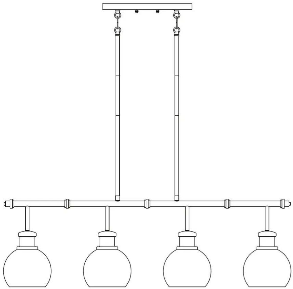
Line drawing of a double-lens hanging fixture with four round domes and vertical rods (no text or symbols)ATTACH YOUR RECEIPT HERE
Serial Number ____ Purchase Date ____

Intertek
text_image
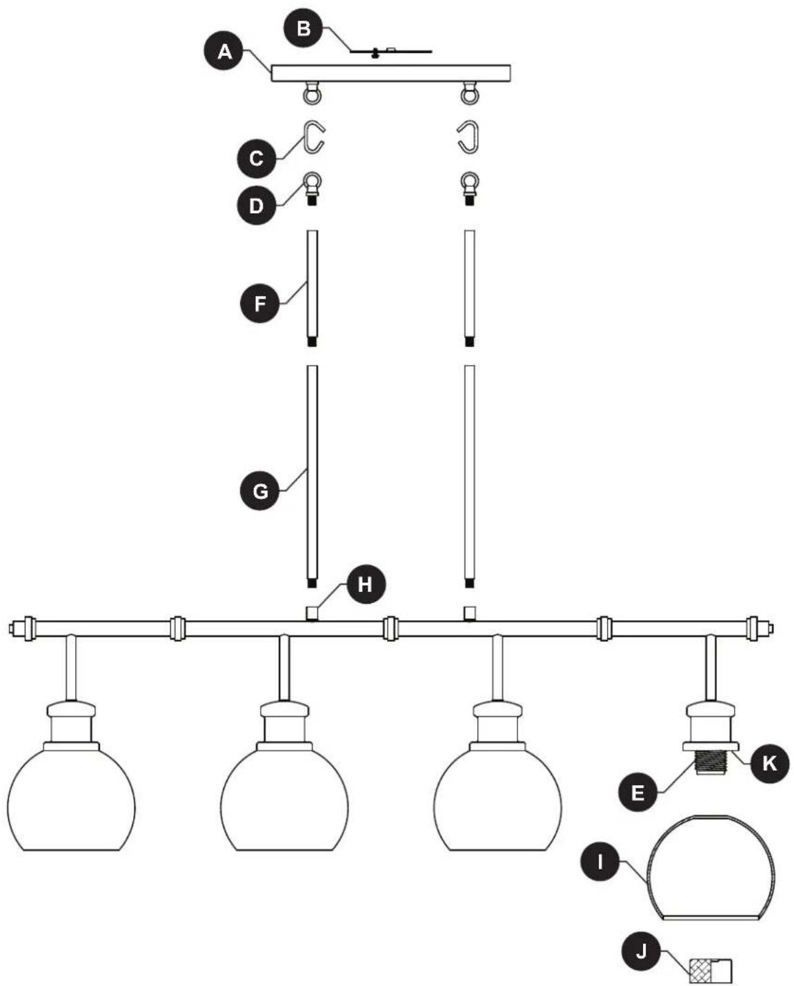
Diagram of a laboratory apparatus with labeled components including test tubes, flasks, and hanging weights| PART | DESCRIPTION | QTY. |
| A | Canopy | 1 |
| B | Mounting Bracket | 1 |
| C | Open Chain Link | 2 |
| D | Fixture Loop | 2 |
| E | Socket | 4 |
| F | 6" Threaded Pipe | 4 |
| PART | DESCRIPTION | QTY. |
| G | 12” Threaded Pipe | 4 |
| H | Coupling | 2 |
| I | Glass Shade | 4 |
| J | Socket Ring | 4 |
| K | Socket Base | 4 |
text_image
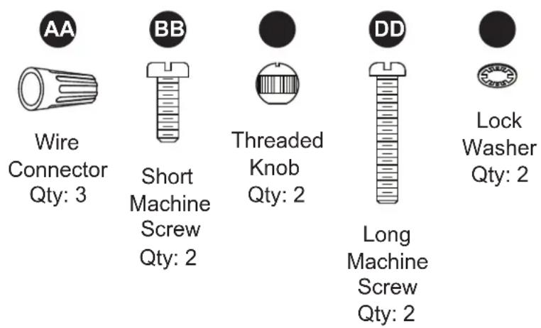
AA Wire Connector Qty: 3 BB Short Machine Screw Qty: 2 Threaded Knob Qty: 2 DD Long Machine Screw Qty: 2 Lock Washer Qty: 2
SAFETY INFORMATION
Please read and understand this entire manual before attempting to assemble, operate or install the product.

WARNING
- CAUTION – RISK OF SHOCK –
Disconnect Power at the main circuit breaker panel or main fusebox before starting and during the installation. - WARNING:
This fixture is intended for installation in accordance with the National Electrical Code (NEC) and all local code specifications. If you are not familiar with code requirements, installation by a certified electrician is recommended. - Do not use bulbs with wattage greater than specified on this fixture.
• California Proposition 65

WARNING: This product can expose you to chemicals including lead, which is known to the State of California to cause cancer, birth defects, or other reproductive harm. For more information, go to http://www.P65Warnings.ca.gov
CAUTION
- If you have any doubts about how to install this lighting fixture, or if the fixture fails to operate completely, please contact a licensed electrical contractor.
- All parts must be used as indicated in these instructions. Do not substitute any parts, leave parts out, or use any parts that are worn out or broken. Failure to obey this instruction could invalidate ETL listing and/or C.S.A. certification of this fixture.
PREPARATION
Before beginning assembly of product, make sure all parts are present. Compare parts with package contents list and hardware contents list. If any part is missing or damaged, do not attempt to assemble the product.
Estimated assembly time: 30 minutes to 1 hour
Tools Required for Assembly (not included): Phillips screwdriver, flathead screwdriver, wire strippers, electrical tape, ladder, safety glasses, pliers (2).
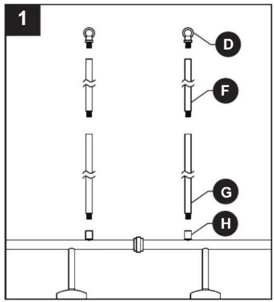
- Screw 12 inch threaded pipe (G) into coupling (H). Next, screw 6 inch threaded pipe (F) into 12 inch threaded pipe (G). Finally, screw fixture loop (D) into 6 inch threaded pipe (F).
Repeat on other side of fixture.
NOTE: The electrical cable will need to get pulled through the individual parts as they are installed on this and later steps.
NOTE: The hanging height for this fixture is adjustable. Add or subtract threaded pipes to achieve the desired height.
- Using the open chain links (C), connect fixture loops (D) to loops on canopy (A).
CAUTION: To avoid damage from falling, make sure the open chain links are fully closed once assembled.
text_image
1 D F G H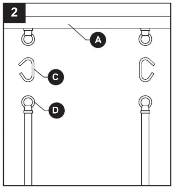
text_image
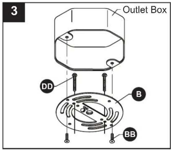
2 A C D- Orient the mounting bracket (B) so the raised center portion protrudes into the outlet box (not included). Insert long machine screws (DD) through mounting bracket (B) so the long machine screws (DD) protrude downward. Connect the mounting bracket (B) to the outlet box with short machine screws (BB).
Hardware Used
| BB | Short Machine Screw | 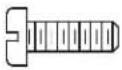 | x 2 |
| DD | Long Machine Screw | 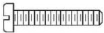 | x 2 |
- Wire connection guide:
Ground wire:
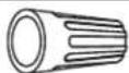
- For installation in the United States: Wrap ground wire from outlet box around ground screw preassembled on mounting bracket (B) no less than 2 in. from wire end. Tighten ground screw. If fixture is supplied with a ground wire, connect to outlet ground wire with a wire connector (AA). - For installation in Canada: If fixture is supplied with ground wire, wrap ground wire around ground screw on mounting bracket (B). Tighten ground screw. Connect fixture ground wire to outlet ground wire with a wire connector (AA).
Supply wires:
- Connect the Neutral (White) supply wire from the outlet box to the Neutral fixture wire (White or Parallel Cord "D" shaped and ribbed).
- Connect the Hot (Black) supply wire from the outlet box to the Hot fixture wire (Black or Parallel Cord round and smooth).
Hardware Used

text_image
3 Outlet Box DD B BB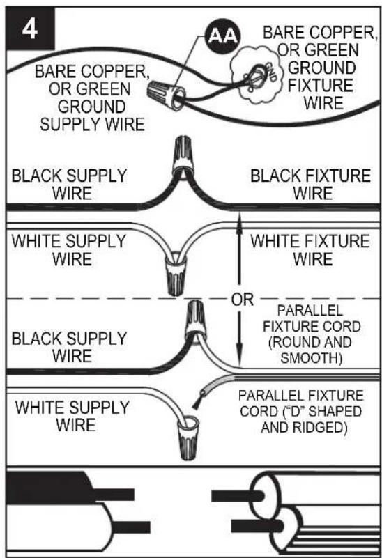
flowchart
graph TD
    A["Black Supply Wire"] --> B["BARE COPPER, OR GREEN GROUND SUPPLY WIRE"]
    B --> C["Black FIXTURE WIRE"]
    D["WHITE SUPPLY WIRE"] --> E["OR PARALLEL FIXTURE CORD (ROUND AND SMOOTH)"]
    E --> F["PARALLEL FIXTURE CORD ("D" SHAPED AND RIDGED)"]
    G["Black Supply Wire"] --> H["PARALLEL FIXTURE CORD (Round AND Smooth)"]
NOTE:
Fixture wires will either be:
- Black and White.
- Parallel Cord SPT-1 lamp wire with one round smooth wire and one "D" shaped ribbed wire.
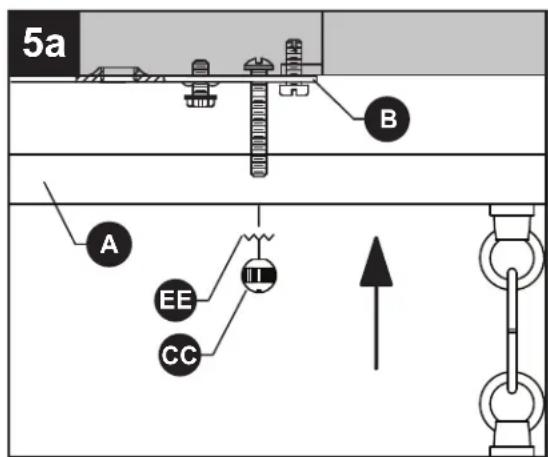
5a. Pass canopy (A) over the long machine screws protruding from mounting bracket (B) and secure with lock washers (EE) and threaded knobs (CC).
NOTE: Make sure all wires are inside of canopy (A) and do not get pinched between canopy (A) and mounting bracket (B), or canopy (A) and ceiling.
Hardware Used
| CC | Threaded Knob |  | x 2 |
| EE | Lock washer |  | x 2 |
text_image
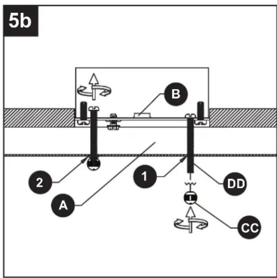
5a A B EE CC II5b. NOTE: The bottom edge of an outlet box should be flush with the bottom surface of a ceiling. However, many boxes are recessed into the ceiling. The long machine screws (DD) are designed to have extra length to accommodate to various box depths.
1) The long machine screws (DD) may, at first, protrude too far past the surface of the canopy (A).
2) Screw the threaded knobs (CC) onto the long machine screws (DD). The screws will back thread into the mounting bracket (B) until the canopy (A) is tight against the ceiling.
- Carefully pass small opening in glass shade (I) over socket (E), and seat glass shade (I) on socket base (K). While holding glass shade (I) in place, thread socket ring (J) onto threads of socket (E). Tighten socket ring (J) to secure glass shade (I) in place. DO NOT OVER-TIGHTEN.
Repeat for remaining glass shades (I).
text_image
5b A 2 1 B DD CC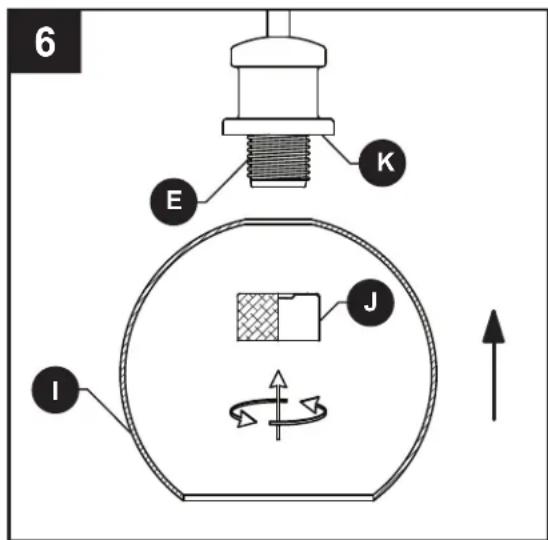
text_image
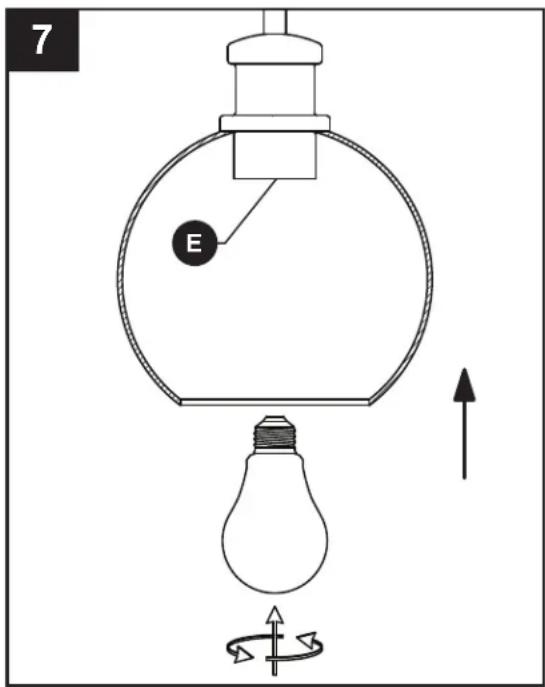
6 E K J I- Insert 60-watt max. medium-base bulb or LED equivalent (not included) into socket (E).
Repeat for remaining sockets (E).
text_image
7 ECARE AND MAINTENANCE
• Always be certain that electric current is turned off before cleaning this item.
- Use a soft, moist cloth with mild non-abrasive soap to clean fixture. Never use glass cleaner on fixture, as it will damage the metal finish.
- All glass shades may be washed in a towel-lined sink with warm water and mild soap. Do not wash shades in an automatic dishwasher.
TROUBLESHOOTING
| PROBLEM POSSIBLE CAUSE CORRECTIVE ACTION | ||
| Fixture does not light. | 1. Fixture may be wired incorrectly.2. Worn or broken bulb. 2. Replace bulb. | 1. Check wiring. |
natural_image
Pure electrical circuit lines without any symbolsJOIGNEZ VOTRE REÇU ICI
text_image
Diagram of a laboratory apparatus with labeled components including test tubes, glassware, and equipment parts.text_image
1 D F G H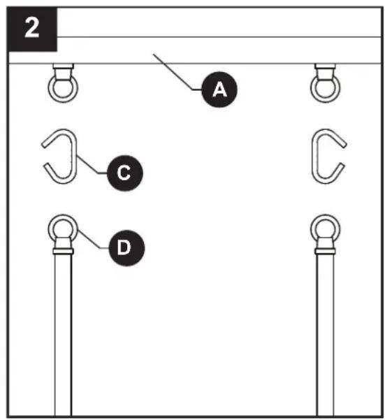
text_image
2 A C Dtext_image
6 E K J IKICHLER.
natural_image
Pure electrical circuit lines without any symbolsADJUNTE SU RECIBO AQUÍ

text_image
Diagram of a laboratory apparatus with labeled components including test tubes, glassware, and equipment parts.text_image
1 D F G H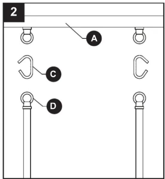
text_image
2 A C Dtext_image
6 E K J IKICHLER.