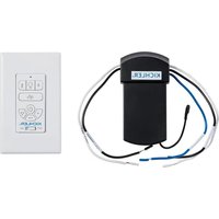
370146 - Lighting Kichler - Free user manual and instructions
Find the device manual for free 370146 Kichler in PDF.


| Product Type | Wireless remote control for ceiling fan with light dimmer |
| Brand | Kichler |
| Model | 370146 |
| Transmitter dimensions (approx.) | 12 x 5 x 2 cm (estimated) |
| Receiver dimensions (approx.) | 7 x 5 x 3 cm (estimated) |
| Receiver weight | 0.0381 kg |
| Power supply | 120 V AC, 60 Hz |
| Main functions | Fan speed control (3 speeds), light control with dimming, breeze mode, reverse rotation, fan on/off |
| Transmission range | Up to 9 m (30 ft) |
| Compatibility | Ceiling fans with compatible receiver (black, white, blue wires) |
| Number of transmitters per receiver | Up to 2 |
| Care and cleaning | Clean with a dry cloth. Do not use abrasive or liquid cleaners. |
| Safety | Disconnect power before installation. Use only with a 120V/60Hz circuit. Do not use with a variable resistor or solid-state dimmer. For indoor use (transmitter) and damp/wet locations (receiver). |
| Spare parts and repairability | Contact Kichler customer service at 866.558.5706 for replacement parts. |
| General information | Compliant with FCC and ISED Canada. Manufactured by Kichler Lighting LLC, Solon, OH, USA. |
Frequently Asked Questions - 370146 Kichler
User questions about 370146 Kichler
0 question about this device. Answer the ones you know or ask your own.
Ask a new question about this device
Download the instructions for your Lighting in PDF format for free! Find your manual 370146 - Kichler and take your electronic device back in hand. On this page are published all the documents necessary for the use of your device. 370146 by Kichler.
USER MANUAL 370146 Kichler
AC BASIC FAN IN-WALL TRANSMITTERS (WIRED)
AC BASIC FAN IN-WALL KITS (WIRED)
Product images may vary slightly from actual product.
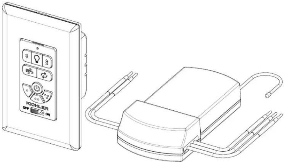
natural_image
Technical line drawing of a device with control panel and connected enclosure (no text or symbols)READ AND SAVE THESE INSTRUCTIONS
INSTRUCTION MANUAL
Models# 370146, 370156, 370145, 370155
TABLE OF CONTENTS
SAFETY RULES....2
TOOLS REQUIRED....2
PACKAGE CONTENTS 2
ELECTRICAL CONNECTIONS....3
PAIRING A TRANSMITTER TO A RECEIVER 5
UNPAIRING A TRANSMITTER FROM A RECEIVER .... 5
OPERATING INSTRUCTIONS....6
TROUBLESHOOTING....7
FCC INFORMATION....7
ISEDC INFORMATION....7
SAFETY RULES
READ AND SAVE THESE INSTRUCTIONS
- CAUTION – RISK OF SHOCK: Disconnect Power at the main circuit breaker panel or main fusebox before starting and during the installation.
- WARNING: All wiring must be in accordance with the National Electrical Code "ANSI/NFPA 70" and local electrical codes. Electrical installation should be performed by a qualified licensed electrician.
- The supply to the receiver should be connected through a mains switch, i.e. existing wall switch.
- After receiver is installed into the ceiling mounting bracket of the fan, the ceiling fan canopy should be reinstalled to ensure proper protection of the receiver and wiring.
- This unit is to be used for the control of ceiling fan and in an AC120V 60Hz power supply only.
- The receiver is acceptable for installation in damp and wet rated fans, but cannot be submerged in water. The transmitter is only to be installed indoors.
- CAUTION: To reduce the risk of fire or injury, do not use this product in conjunction with any variable (rheostat) or solid-state wall control.
- After making electrical connections, spliced conductors should be turned upward and pushed carefully up into outlet box. The wires should be spread apart with the grounded conductor and the equipment-grounding conductor on one side of the outlet box and the ungrounded conductor on the other side of the outlet box.
-
Electrical diagrams are reference only.
-
Transmitters that DO NOT include a "Reverse" Button:
WARNING: Do not operate reversing switch while fan blades are in motion. Fan must be turned off and blades stopped before reversing blade direction.
Transmitters that include a "Reverse" Button:
To operate the reverse function on this fan, press the "Reverse" Button on the transmitter while the fan is running.
- IMPORTANT:
IF INSTALLING TO A PULL CHAIN FAN THE CEILING FAN MUST BE SET TO HIGH SPEED AND THE LIGHT KIT (IF APPLICABLE) MUST BE SET TO THE ON POSITION BEFORE DISCONNECTING POWER AT THE MAIN CIRCUIT BREAKER PANEL OR MAIN FUSEBOX AND INSTALLING THE CONTROL.
Receiver: Weight 0.0381 KGS (0.084 LBS)
TOOLS REQUIRED
• Phillips Screwdriver
- Flathead Screwdriver
- Wire Cutters
- Step Ladder
PACKAGE CONTENTS
• Transmitter, Screws, Wall Plate, Mounting Plate
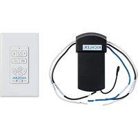
- Receiver (In-Wall Transmitter and Receiver Kits Only)
- Wire Nuts
ELECTRICAL CONNECTIONS
CAUTION: To avoid possible electrical shock, be sure you have turned off the power at the main circuit panel.
IMPORTANT: IF INSTALLING TO A PULL CHAIN FAN THE CEILING FAN MUST BE SET TO HIGH SPEED AND THE LIGHT KIT (IF APPLICABLE) MUST BE SET TO THE ON POSITION BEFORE DISCONNECTING POWER AT THE MAIN CIRCUIT BREAKER PANEL OR MAIN FUSEBOX AND INSTALLING THE CONTROL.
CAUTION: Incorrect wire connection will damage the receiver.
WARNING: If your house wires are different colors than referenced in this manual, stop immediately. A professional electrician is recommended to determine proper wiring.
Follow the steps below to connect the fan to your household wiring. Use the wire connecting nuts supplied with your transmitter. Secure the connectors with electrical tape. Make sure there are no loose wire strands or connections.
WARNING: Check to see that all connections are tight, including ground, and that no bare wire is visible at the wire connections.
Step 1. Insert the receiver into the ceiling mounting bracket with the flat side of the receiver facing the ceiling. (Fig. 1) For best performance, make sure the black antenna wire (on the end of the receiver) remains extended, and does not become tangled with the electrical wires.
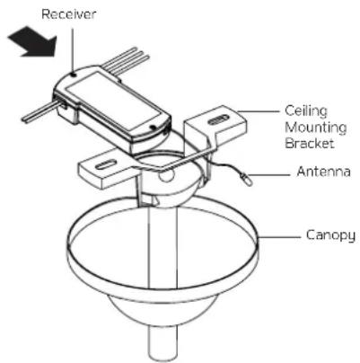
Fig. 1
Step 2. Fan Motor to Receiver Electrical Connections: (Fig. 2)
- Connect the black wire from the fan to the black wire marked "TO MOTOR L" on the receiver.
- Connect the white wire from the fan to the white wire marked "TO MOTOR N" on the receiver.
- Connect the blue wire from the fan to the blue wire marked "FOR LIGHT" on the receiver.
Secure all the wire connections with the plastic wire nuts provided and make sure there are no loose strands or connections.
Step 3. Receiver to Supply Wires Electrical Connections: (Fig. 2)
- Connect the black (LOAD) wire from the ceiling outlet box to the black wire marked "AC IN L" from the receiver.
- Connect the white (NEUTRAL) wire from the ceiling outlet box to the white wire marked "AC IN N" from the receiver.
Secure the wire connections with the plastic wire nuts provided and make sure there are no loose strands or connections.
Step 4. After connecting the wires, turn the wire connecting nuts upward, and push the wiring into the outlet box. Spread them apart so that the green (ground) and white (neutral) wires are on one side of the outlet box and the black (hot) wires are on the other side.
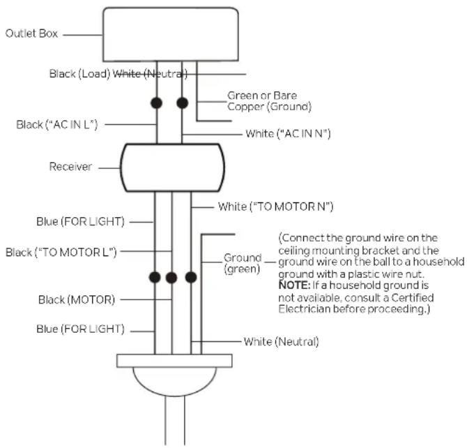
Fig. 2
ELECTRICAL CONNECTIONS (continued)
Step 5. Once all connections have been made, reinstall the canopy to the ceiling mounting bracket. (Fig. 3).
NOTE: Fan must be installed at a maximum distance of 30 feet from the transmitter for optimal signal transmission between the transmitter and the fan's receiver.
Step 6. Removing the Existing Wall Switch: (Fig. 4)
Remove the existing wall plate and the existing switch from the wall outlet box, and disconnect the wires. (Fig. 4)
Step 7. Transmitter to Supply Wires and Transmitter to Receiver Electrical Connections: (Fig. 7)
NOTE: Before installing the transmitter, slide the OFF/ON switch on the face of the transmitter to "OFF". (Fig. 5)
NOTE: Before installing the transmitter, remove the wall plate (insert a small, flathead screwdriver into the slots at the top and bottom of the mounting plate, and carefully pry the wall plate off of the mounting plate) (Fig. 6) then remove the face plate (insert a small, flathead screwdriver into the slots at the top and left side of the face plate, and carefully pry the face plate off of the transmitter). (Fig. 6)
- Connect the black lead wire (HOT) from the wall outlet box to black wire marked "AC IN" from transmitter.
- Connect the black lead wire (LOAD) from the wall outlet box to black wire marked "TO MOTOR L" from transmitter.
- Connect the white ("AC IN N") lead wire (NEUTRAL) from the wall outlet box to the white ("TO MOTOR N") lead wire (NEUTRAL) from the wall outlet box.
Secure the wire connections with the plastic wire nuts provided and make sure there are no loose strands or connections.
Step 8. Carefully tuck the wire connections back inside the wall outlet box and spread them apart so that the green (ground) and white (neutral) wires are on one side of the outlet box and the black (hot) wires are on the other side.
Step 9. Secure the mounting plate and transmitter to the wall outlet box with the screws provided.
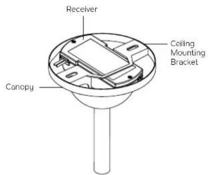
Fig. 3
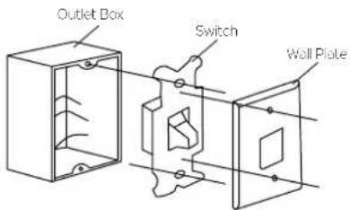
Fig. 4

Fig. 5
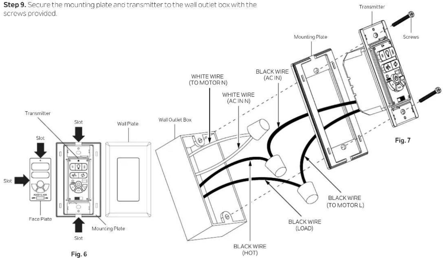
PAIRING A TRANSMITTER TO A RECEIVER
WARNING: Make sure the power is completely disconnected at the circuit breaker or fusebox before starting this process.
IMPORTANT: Fan motor, fan blades, and light kit (if applicable) MUST be installed before the pairing process can begin.
NOTE: If using an in-wall transmitter and also a hand held transmitter with the same fan, the in-wall transmitter should be programmed first, before programming the hand held transmitter.
NOTE: Only one transmitter at a time can be paired using this process. To pair an additional transmitter, repeat this process.
NOTE: A maximum of 2 transmitters can be paired to a receiver. If pairing more than 2 transmitters to the same receiver is attempted, the receiver will begin to remove previous pairings from memory.
NOTE: Wait to pair the transmitter to the receiver if another fan has been turned on in the last 2 minutes. If a different fan has been on for less than 2 minutes when the LEARN button is pressed, the transmitter will pair to both fans.
Step 1. Make sure that the OFF/ON switch on the face of the transmitter is set to "OFF" (Fig. 8), then restore power to the fan at the circuit breaker or fuse box.
Step 2. Slide the OFF/ON switch on the face of the transmitter to the "ON" position (Fig. 9), then press the LEARN button on the transmitter. (Fig. 10) The fan will change to medium speed and the light kit (if applicable) will toggle (if the light kit was previously on, it will switch to off. If the light kit was previously off, it will switch to on). This confirms that the pairing process is complete.
NOTE: If the LEARN button is not pressed within 2 minutes, slide the OFF/ON switch on the face of the transmitter to the "OFF" position, then repeat Step 2.
NOTE: Try different speed settings on the transmitter to make sure the fan is fully functional. If programming is unsuccessful, slide the OFF/ON switch on the face of the transmitter to the "OFF" position, then repeat Step 2.
Step 3. Snap the face plate back into place on the front of the transmitter first, then snap the wall plate into place on the mounting plate. (Fig. 11A)
NOTE: To prevent damage to the face plate and wall plate, make sure that the 4 pins on the back of the face plate are aligned with the 4 holes on the front of the transmitter, and that the 4 clips on the back of the wall plate are aligned with the 4 slots in the face of the mounting plate. (Fig. 11B)
UNPAIRING A TRANSMITTER FROM A RECEIVER
NOTE: After the pairing process is complete, a transmitter can be unpaired from a receiver by following the "PAIRING A TRANSMITTER TO A RECEIVER" process a second time.
NOTE: To access the LEARN button, remove the wall plate (insert a small, flathead screwdriver into the slots at the top and bottom of the mounting plate, and carefully pry the wall plate off of the mounting plate) (Fig. 6) then remove the face plate (insert a small, flathead screwdriver into the slots at the top and left side of the face plate, and carefully pry the face plate off of the transmitter). (Fig. 6)

Fig. 8

Fig. 9
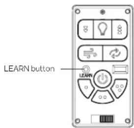
Fig. 10
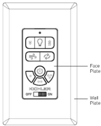
Fig. 11A
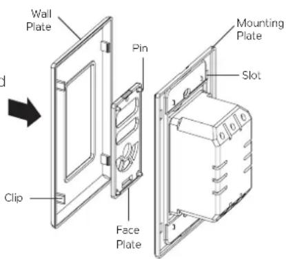
Fig. 11B
NOTE: Please keep this page in case future reprogramming is needed, or an additional transmitter is added.
OPERATING INSTRUCTIONS
TRANSMITTER OPERATION: (Fig. 12)
NOTE: The OFF/ON switch on the face of the transmitter must be set to "ON" before fan operation can begin.

Light Button:
Press once to turn the light on or off.

Brightness Button:
Press and hold to brighten the light to the desired level, then release.

Dimming Button:
Press and hold to dim the light to the desired level, then release.

Breeze Mode Button:
Fan speed will vary to simulate a natural breeze. Press a second time to stop Breeze Mode, or press a Fan Speed button to stop Breeze Mode.

Off Button:
Press once to stop the fan. Press a second time to start the fan at the previous fan speed.

High Speed Button:
Press once to start the fan at high speed.

Medium Speed Button:
Press once to start the fan at medium speed.

Low Speed Button:
Press once to start the fan at low speed.

Reverse Button: (if included on your transmitter).
While the fan is running, press the reverse button once, and the fan will reverse direction.
WARNING: If a Reverse Button is not included on your transmitter, do not operate reversing switch while fan blades are in motion. Fan must be turned off and blades stopped before reversing blade direction.
WHY REVERSE THE ROTATION OF A FAN?
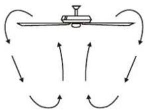
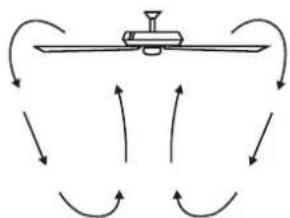
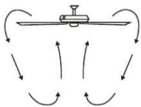
Warm weather - When the fan is rotating "FORWARD" (fan rotates counterclockwise) the temperature of the room becomes cooler. A downward airflow creates a cooling effect as shown in (Fig. 13). This allows you to set your air conditioner on a warmer setting without affecting your comfort.
Cool weather - When the fan is rotating in "REVERSE" (fan rotates clockwise) the temperature of the room becomes warmer. An upward airflow moves warm air off the ceiling area as shown in (Fig. 14). This allows you to set your heating unit on a cooler setting without affecting your comfort.
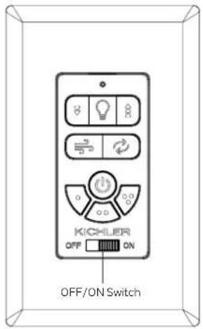
Fig. 12
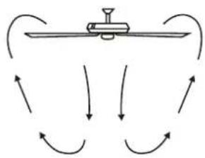
natural_image
Diagram showing curved arrows pointing toward a mechanical device or lever system (no text or symbols)Fig. 13
natural_image
Diagram showing airflow around a mechanical device with curved arrows indicating direction (no text or symbols)Fig. 14
TROUBLESHOOTING
Problem
SolutionSolution
Fan will not start.
- Check circuit fuses or breakers.
- Make sure that the OFF/ON switch on the control is set to the "ON" position.
- Check all electrical connections to ensure proper contact. CAUTION: Make sure the main power is OFF when checking any electrical connection.
Remote control malfunction.
- Ceiling Fans with remote control systems CAN NOT be operated in conjunction with any other control system EXCEPT a basic On/Off wall switch if desired.
- Make sure the black antenna wire on the receiver is NOT tangled with any other electrical wires and is extended around the inside of the ceiling canopy. CAUTION: Make sure main power is off.
FCC INFORMATION
This device complies with part 15 of the FCC Rules. Operation is subject to the following two conditions:
1) This device may not cause harmful interference, and
2) This device must accept any interference received, including interference that may cause undesired operation.
Note: This equipment has been tested and found to comply with the limits for a Class B digital device, pursuant to part 15 of the FCC Rules. These limits are designed to provide reasonable protection against harmful interference in a residential installation. This equipment generates, uses and can radiate radio frequency energy and, if not installed and used in accordance with the instructions, may cause harmful interference to radio communications. However, there is no guarantee that interference will not occur in a particular installation. If this equipment does cause harmful interference to radio or television reception, which can be determined by turning the equipment off and on, the user is encouraged to try to correct the interference by one or more of the following measures:
- Reorient or relocate the receiving antenna.
- Increase the separation between the equipment and receiver.
- Connect the equipment into an outlet on a circuit different from that to which the receiver is connected.
- Consult the dealer or an experienced radio/TV technician for help.
ISEDC INFORMATION
ISEDC Warning:
This device contains licence-exempt transmitter(s) that comply with Innovation, Science and Economic Development Canada's licence-exempt RSS(s). Operation is subject to the following two conditions:
1) This device may not cause interference.
2) This device must accept any interference, including interference that may cause undesired operation of the device.
RENSEIGNEMENTS DE ISEDC
© Kichler Lighting LLC. All Rights Reserved.
ÉMETTEURS MURAUX POUR VENTILATEUR DE BASE CA (CÂBLÉS) TROUSSES MURALES POUR VENTILATEUR DE BASE CA (CÂBLÉS)
natural_image
Technical line drawing of a device with control panel and connected enclosure (no text or symbols)LISEZ ET CONSERVEZ CES INSTRUCTIONS
MANUEL D'INSTRUCTIONS
Fig. 10
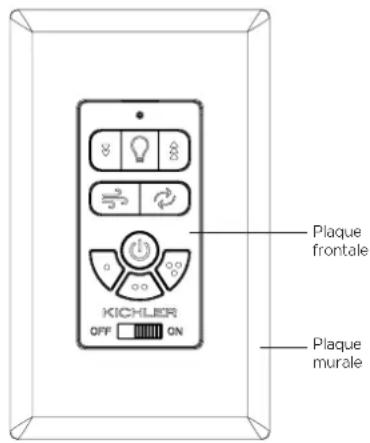
Fig. 11A
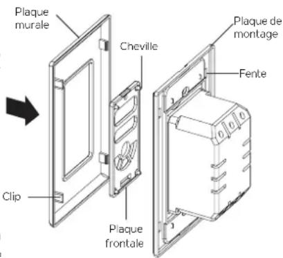
Fig. 11B
natural_image
Pure diagram of a mechanical lever system with curved arrows indicating motion or force direction (no text or symbols)Fig. 13
natural_image
Diagram of a mechanical lever system with curved arrows indicating rotational motion (no text or labels)Fig. 14
DÉPANNAGE
Problème
SolutionSolution
This device contains licence-exempt transmitter(s) that comply with Innovation, Science and Economic Development Canada's licence-exempt RSS(s). Operation is subject to the following two conditions:
1) This device may not cause interference.
2) This device must accept any interference, including interference that may cause undesired operation of the device.
RENSEIGNEMENTS DE ISEDC
natural_image
Technical line drawing of a device with control panel and connected enclosure (no text or symbols)LEA Y GUARDE ESTAS INSTRUCCIONES
natural_image
Diagram of a mechanical or fluid system with curved arrows indicating flow or direction (no text or symbols)Figura 13
natural_image
Diagram of a mechanical or fluid system with curved arrows indicating flow or direction (no text or symbols)Figura 14

- AC BASIC FAN IN-WALL TRANSMITTERS (WIRED)
- AC BASIC FAN IN-WALL KITS (WIRED)
- TABLE OF CONTENTS
- SAFETY RULES
- READ AND SAVE THESE INSTRUCTIONS
- TOOLS REQUIRED
- PACKAGE CONTENTS
- ELECTRICAL CONNECTIONS
- Step 2. Fan Motor to Receiver Electrical Connections: (Fig. 2)
- Step 3. Receiver to Supply Wires Electrical Connections: (Fig. 2)
- ELECTRICAL CONNECTIONS (continued)
- PAIRING A TRANSMITTER TO A RECEIVER
- UNPAIRING A TRANSMITTER FROM A RECEIVER
- OPERATING INSTRUCTIONS
- TRANSMITTER OPERATION: (Fig. 12)
- Light Button:
- Brightness Button:
- Dimming Button:
- Breeze Mode Button:
- Off Button:
- High Speed Button:
- Medium Speed Button:
- Low Speed Button:
- Reverse Button: (if included on your transmitter).
- WHY REVERSE THE ROTATION OF A FAN?
- TROUBLESHOOTING
- Problem
- SolutionSolution
- Fan will not start.
- Remote control malfunction.
- FCC INFORMATION
- ISEDC INFORMATION
- ISEDC Warning:
- RENSEIGNEMENTS DE ISEDC
- ÉMETTEURS MURAUX POUR VENTILATEUR DE BASE CA (CÂBLÉS) TROUSSES MURALES POUR VENTILATEUR DE BASE CA (CÂBLÉS)
- LISEZ ET CONSERVEZ CES INSTRUCTIONS
- MANUEL D'INSTRUCTIONS
- DÉPANNAGE
- Problème
Brand : Kichler
Model : 370146
Category : Lighting