Sayulita 82401 - Lighting Kichler - Free user manual and instructions
Find the device manual for free Sayulita 82401 Kichler in PDF.


User questions about Sayulita 82401 Kichler
0 question about this device. Answer the ones you know or ask your own.
Ask a new question about this device
Download the instructions for your Lighting in PDF format for free! Find your manual Sayulita 82401 - Kichler and take your electronic device back in hand. On this page are published all the documents necessary for the use of your device. Sayulita 82401 by Kichler.
USER MANUAL Sayulita 82401 Kichler
natural_image
Technical line drawing of a mechanical lifting device with a vertical rod and grid-patterned base (no text or symbols)ITEM # 5055203
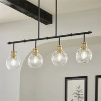
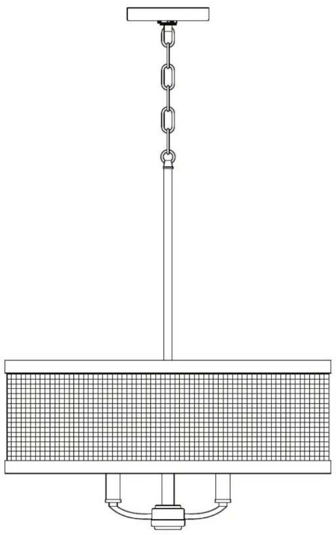
SAYULITA 4-LIGHT CHANDELIER
MODEL # 82401
Français p. 9
Español p. 17
ATTACH YOUR RECEIPT HERE
Serial Number ____ Purchase Date ____

Questions, problems, missing parts? Before returning to your retailer, call our customer service department at 800-554-6504, 8 a.m. - 4:30 p.m, EST, Monday - Friday. kichler.com/customer-care/contact-us
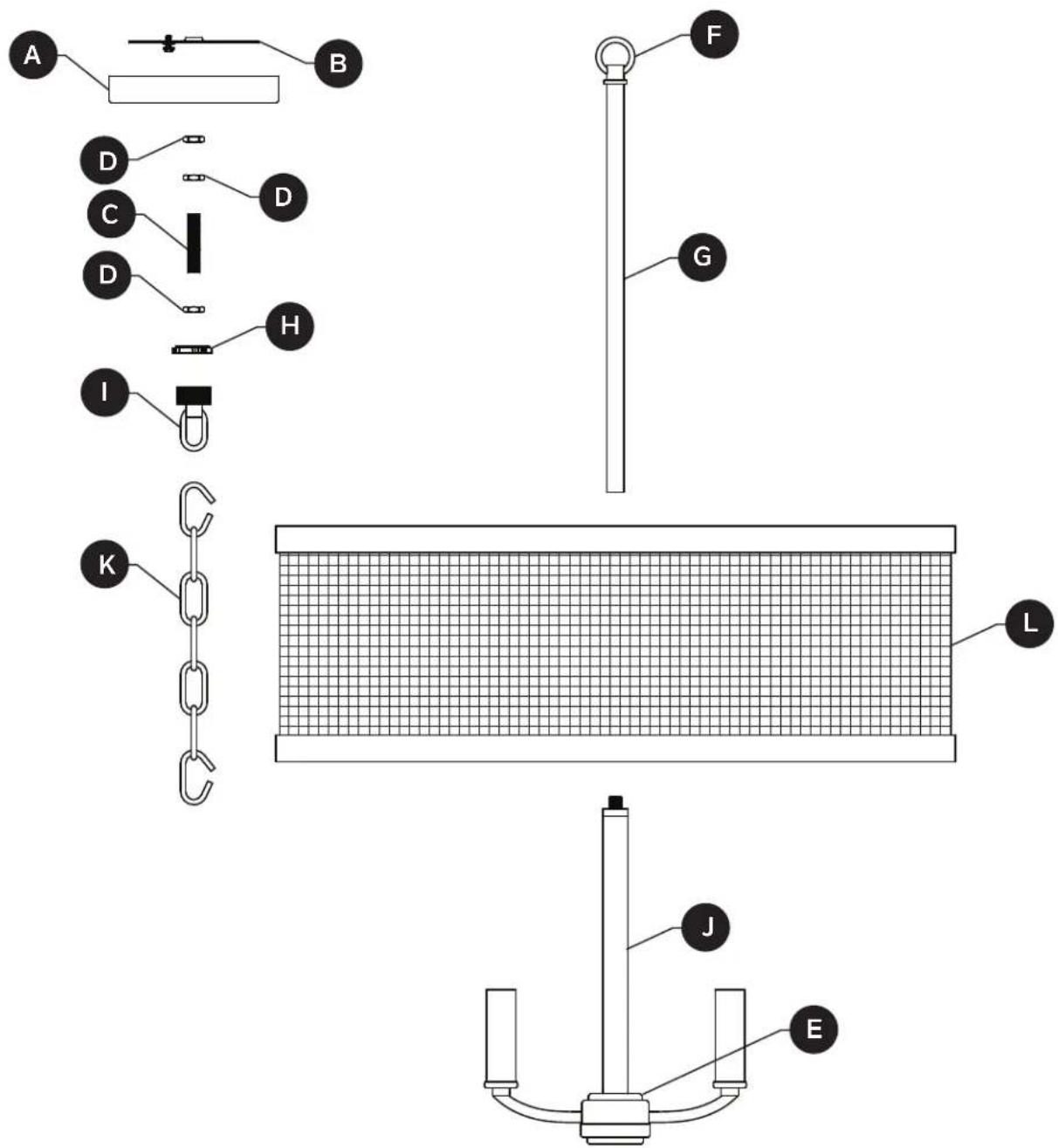
| PART DESCRIPTION QTY | ||
| A | Canopy | 1 |
| B | Mounting Bracket | 1 |
| C | Threaded Nipple | 1 |
| D | Hex Nut | 3 |
| E | Socket Cluster | 1 |
| F | Loop | 1 |
| PART DESCRIPTION QTY | ||
| G | Threaded Pipe | 1 |
| H | Screw Collar Ring | 1 |
| I | Screw Collar Loop | 1 |
| J | Support Tube | 1 |
| K | Chain | 1 |
| L | Shade | 1 |
text_image
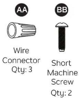
AA Wire Connector Qty: 3 BB Short Machine Screw Qty: 2
SAFETY INFORMATION
Please read and understand this entire manual before attempting to assemble, operate or install the product.

WARNING
• CAUTION - RISK OF SHOCK -
Disconnect Power at the main circuit breaker panel or main fusebox before starting and during the installation.
- WARNING:
This fixture is intended for installation in accordance with the National Electrical Code (NEC) and all local code specifications. If you are not familiar with code requirements, installation by a certified electrician is recommended.
- Do not use bulbs with wattage greater than specified on this fixture.
• California Proposition 65

WARNING: This product can expose you to chemicals including lead, which is known to the State of California to cause cancer, birth defects, or other reproductive harm. For more information, go to http://www.P65Warnings.ca.gov
CAUTION
- If you have any doubts about how to install this lighting fixture, or if the fixture fails to operate completely, please contact a licensed electrical contractor.
- All parts must be used as indicated in these instructions. Do not substitute any parts, leave parts out, or use any parts that are worn out or broken. Failure to obey this instruction could invalidate ETL listing and/or C.S.A. certification of this fixture.
PREPARATION
Before beginning assembly of product, make sure all parts are present. Compare parts with package contents list and hardware contents list. If any part is missing or damaged, do not attempt to assemble the product.
Estimated assembly time: 30 minutes to 1 hour
Tools Required for Assembly (not included): Phillips screwdriver, flathead screwdriver, wire strippers, electrical tape, ladder, safety glasses, pliers (2).
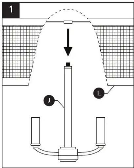
- Carefully lower shade (L) onto support tube (J), passing hole in center hub of shade (L) over threads protruding from top of support tube (J), and seat center hub of shade (L) on top of support tube (J).
NOTE: The electrical cable will need to get pulled through the individual parts as they are installed on this and later steps.
text_image
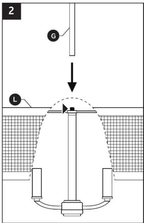
1 J L- While holding shade (L) in place, screw threaded pipe (G) onto threads protruding from top of center hub of shade (L). Tighten to secure shade (L) in place.
NOTE: Thread locking compound must be applied to all stem threads as noted with (▶) symbol to prevent accidental rotation of fixture during cleaning, relamping, etc.
text_image
2 G L-
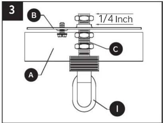
Position threaded nipple (C) in mounting bracket (B) so that, when mounted:
-
The threaded nipple (C) will protrude a minimum of 1/4 inch beyond the raised center portion of the bracket (B).
- The threaded nipple (C) height should be positioned so that 1/2 the exterior threads of the screw collar loop (I) will extend past the canopy (A), when it is mounted.
NOTE: Canopy (A) is only needed to determine the position of the threaded nipple (C) and screw collar loop (I). It will be installed later.
-
Once the proper position of the threaded nipple (C) and mounting bracket (B) has been determined, secure with hex nuts (D) as follows:
-
Screw one hex nut (D) onto the threaded nipple (C) and tighten against the raised portion of the mounting bracket (B).
- Screw another hex nut (D) onto the threaded nipple (C) and tighten against the flat portion of the mounting bracket (B).
-
Screw the remaining hex nut (D) onto threaded nipple (C) and tighten against the screw collar loop (I).
-
Connect mounting bracket (B) to the outlet box (not included) with short machine screws (BB).
Hardware Used

Short Machine Screw
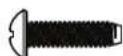
×2
text_image
3 B 1/4 Inch C A I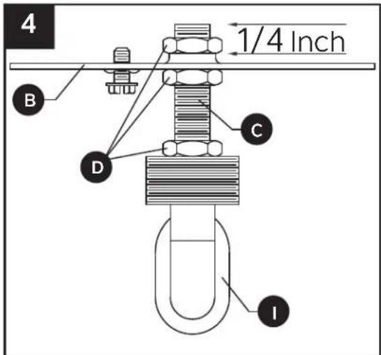
text_image
4 1/4 Inch B C D I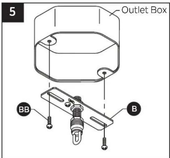
text_image
5 Outlet Box BB B6. To open chain links:
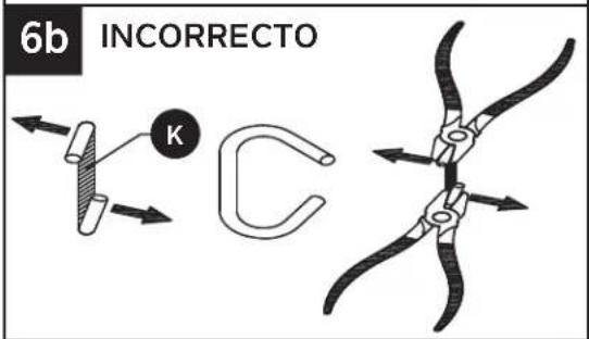
Locate the split in the chain link (K) which will need to be opened and removed. Put one pair of pliers (not included) on each side of the split and rotate the pliers in opposite directions to open the link's split. The open link should be shaped like the letter "C".
Do not twist the ends of the link sideways so that the open link cannot lay flat.
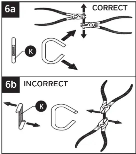
text_image
6a CORRECT K 6b INCORRECT K- Thread chain (K) through screw collar ring (H) and canopy (A). Using the open chain links on chain (K), attach one end to screw collar loop (I) and the other end to threaded pipe with loop (F). Weave the fixture electrical and ground wires through every other chain link and pass through threaded nipple (C) into outlet box. Lower the screw collar ring (H) and canopy (A) over the chain (K).
NOTE: Add or remove chain links once desired length is established. Trim extra cabling leaving six inches of extra wire protruding from the screw collar loop (I) and threaded nipple (C).
CAUTION: To avoid damage from falling, make sure the open chain links are fully closed once assembled.
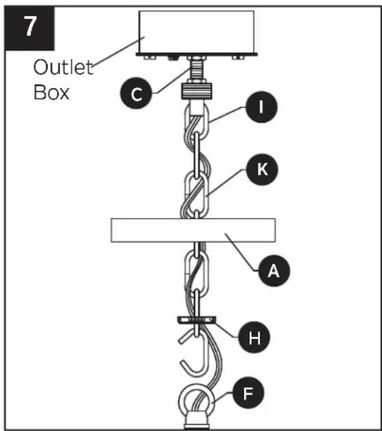
text_image
7 Outlet Box C I K A H F8. Wire connection guide:
Ground wire:
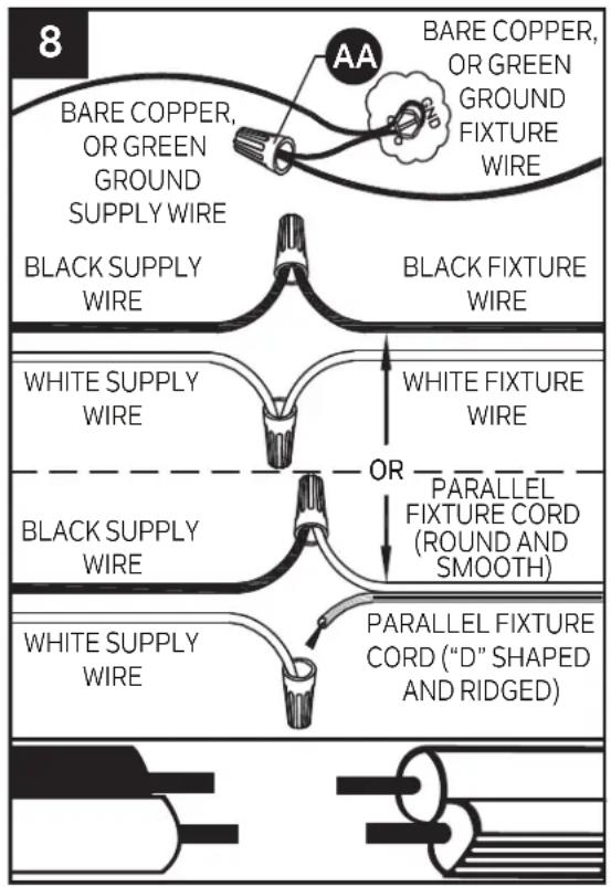
- For installation in the United States: Wrap ground wire from outlet box around ground screw on mounting bracket (B) no less than 2 in. from wire end. Tighten ground screw. If fixture is supplied with a ground wire, connect to outlet ground wire with a wire connector (AA).
- For installation in Canada: If fixture is supplied with ground wire, wrap ground wire around ground screw on mounting bracket (B). Tighten ground screw. Connect fixture ground wire to outlet ground wire with a wire connector (AA).
Supply wires:
- Connect the Neutral (White) supply wire from the outlet box to the Neutral fixture wire (White or Parallel Cord "D" shaped and ribbed).
- Connect the Hot (Black) supply wire from the outlet box to the Hot fixture wire (Black or Parallel Cord round and smooth).
NOTE:
Fixture wires will either be:
- Black and White.
- Parallel Cord SPT-1 lamp wire with one round smooth wire and one "D" shaped ribbed wire.
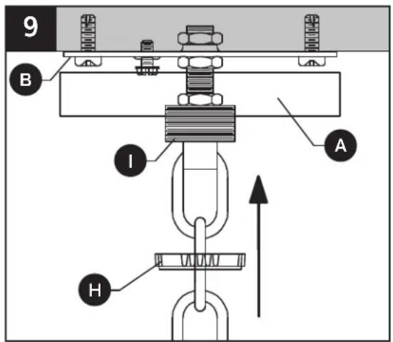
9. Pass canopy (A) over the screw collar loop (I).
Attach screw collar ring (H) to screw collar loop (I) to secure canopy (A).
NOTE: Make sure all wires are inside of canopy (A) and do not get pinched between canopy (A) and mounting bracket (B), or canopy (A) and ceiling.
flowchart
graph TD
    A["Black Supply Wire"] --> B["BARE COPPER, OR GREEN GROUND SUPPLY WIRE"]
    B --> C["Black Supply Wire"]
    D["White Supply Wire"] --> E["OR PARALLEL FIXTURE CORD (ROUND AND SMOOTH)"]
    E --> F["PARALLEL FIXTURE CORD ("D" SHAPED AND RIDGED)"]
    G["BARE COPPER, OR GREEN GROUND FIXTURE WIRE"] --> H["Black Supply Wire"]
    I["White Supply Wire"] --> J["OR PARALLEL FIXTURE CORD (ROUND AND SMOOTH)"]
    J --> K["PARALLEL FIXTURE CORD ("D" SHAPED AND RIDGED)"]
Hardware Used

x 3Wire C
text_image
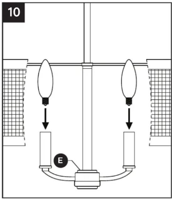
9 B I A H- Insert 60-watt max. candelabra bulbs or LED equivalent (not included) into each socket in socket cluster (E).
text_image
10 ECARE AND MAINTENANCE
• Always be certain that electric current is turned off before cleaning this item.
- Use a soft, moist cloth with mild non-abrasive soap to clean fixture. Never use glass cleaner on fixture, as it will damage the metal finish.
TROUBLESHOOTING
| PROBLEM POSSIBLE CAUSE CORRECTIVE ACTION | ||
| Fixture does not light. | 1. Fixture may be wired incorrectly.2. Worn or broken bulb. | 1. Check wiring.2. Replace bulb. |
KICHLER®
natural_image
Technical line drawing of a mechanical lifting device with a vertical rod and grid-patterned base (no text or symbols)ARTICLE # 5055203
text_image
6a ADÉQUAT K 6b INADÉQUAT Ktext_image
9 B I A Hnatural_image
Technical line drawing of a mechanical lifting device with a vertical rod and grid-patterned base (no text or symbols)ARTÍCULO # 5055203
CANDELABRO DE 4 LUCES SAYULITA
MODELO # 82401
ADJUNTE SU RECIBO AQUÍ
text_image
6a CORRECTO K