
Cami - Boiler COINTRA - Free user manual and instructions
Find the device manual for free Cami COINTRA in PDF.

| Product type | Instantaneous gas water heater, open chamber |
| Brand | Cointra |
| Model | Cami (CAMI 6 / CAMI 11) |
| Gas category | II2H3+ (ES-PT-GB) / II2HM3+ (IT) / II2E+3+ (FR) / I2E+ (BE) / I3+ (BE) |
| Dimensions (approx.) | CAMI 6: H 580 mm, W 310 mm, D 220 mm; CAMI 11: H 600 mm, W 320 mm, D 230 mm |
| Empty weight | CAMI 6: 8.5 kg; CAMI 11: 9.5 kg |
| Power supply | 3 V DC (2 x 1.5 V batteries) |
| Max thermal power | CAMI 6: 11.8 kW; CAMI 11: 21.1 kW (G20 gas) |
| Main functions | Domestic hot water production, electronic ignition, power and temperature adjustment, automatic operation |
| Hot water flow rate (ΔT 25°C) | CAMI 6: 6.0 l/min; CAMI 11: 10.8 l/min |
| Min/max water pressure | 0.2 bar / 10 bar |
| Protection rating | IP X4D |
| Maintenance and cleaning | External cleaning with a soft damp cloth; annual check by a qualified professional (check burner, heat exchanger, electrode, gas/water circuit) |
| Safety | Flue safety thermostat, ionization electrode (flame detection), gas valve, overheat protection, automatic shutdown in case of fault |
| Spare parts and repairability | Use only original spare parts; repairs by a qualified professional only |
| Appliance type | B11BS (natural draft) |
| Compatible gases | Natural gas (G20, G230) and LPG (G31, G30) |
| NOx emissions | Class 6 (<56 mg/kWh) |
| General information | Domestic use, indoor or outdoor installation (from -5°C to +60°C), conforms to CE standards |
Frequently Asked Questions - Cami COINTRA
User questions about Cami COINTRA
0 question about this device. Answer the ones you know or ask your own.
Ask a new question about this device
Download the instructions for your Boiler in PDF format for free! Find your manual Cami - COINTRA and take your electronic device back in hand. On this page are published all the documents necessary for the use of your device. Cami by COINTRA.
USER MANUAL Cami COINTRA
EN USER AND INSTALLATION MANUAL 55
| A Lateral >2cm | |
| B->50cm | |
| C Frontal >2cm |
3 ASSISTÊNCIA E MANUTENÇA
- Read the warnings contained in this manual carefully.
- Once the unit is installed, describe its operation to the user and give them this manual. The manual is an integral part of the product and must be kept in a safe, accessible place for future reference.
- Installation and maintenance must be performed by a registered technician, in accordance with current standards and the manufacturer's instructions. Tampering with the sealed adjustment devices is prohibited.
- Improper installation or lack of appropriate maintenance may result in property damage or injury. The manufacturer will not be liable for damage caused by improper installation or use or, in any case, for failure to comply with the instructions.
- Before performing any cleaning or maintenance operations, unplug the unit from the mains power supply using the power switch or another cut-off device.
- In the event of a malfunction or improper operation, unplug the unit and have it repaired by qualified personnel. Only
contact registered technicians. The unit must only be repaired, and its components replaced, by registered technicians using original replacement parts. Otherwise the safety of the unit may be compromised.
- This unit may only be used for the purpose for which it was expressly designed. Any other use must be considered inappropriate, and therefore hazardous.
- The packing materials are a potential source of danger, and must be kept out of reach of children.
- The unit can be used by children aged at least 8 years and by persons with reduced physical, sensory or mental capabilities, or lacking experience or the necessary knowledge, only if under supervision or they have received instructions on its safe use and the related risks. Children must not play with the unit. Cleaning and maintenance intended to be done by the user can be carried out by children aged at least 8 years only if under supervision..
- Dispose of the unit and its accessories in accordance with current standards.
- The images contained in this manual are a simplified representation of the
product. Such representations may include slight, insignificant differences with respect to the product supplied.
- APPLIANCE INTENDED FOR DOMESTIC USE; NOT VALID FOR INDUSTRIAL USE.

This symbol means "Caution," and is displayed next to safety warnings. Carefully observe such warnings to avoid hazardous situations, property damage, and injury to people and animals.

Important information involving no risk of injury or property damage is indicated by this symbol.

The CE marking certifies that products meet the fundamental requirements of the applicable European directives. The declaration of conformity can be requested from the manufacturer.
The unit is intended for indoor installation, but can also be installed in a partially protected place with temperatures from -5^ to +60^ .
1 USER'S MANUAL 57
1.1 Introduction 57
1.2 Control panel 57
1.3 Turning the heater on and off 57
1.4 Settings 58
1.5 Faults 58
2 INSTALLATION MANUAL 59
2.1 General information 59
2.2 Location 59
2.3Assembling the heater 60
2.4 Hydraulic connections.. 61
2.5 Gas connection 62
2.6 Air and flue gas ducts 62
3 SERVICE AND MAINTENANCE 63
3.1 ADJUSTMENTS 63
3.2 COMMISSIONING 64
3.3 MAINTENANCE 64
3.4 REPLACING THE BATTERIES 65
4 TECHNICAL DATA AND CHARACTERISTICS....66
4.1 Dimensions and connections.. 66
4.2 Overview and main components 67
4.3 Hydraulic circuit 68
4.4 Technical data table 69
4.5 Wiring diagram 71
1 USER'S MANUAL
1.1 Introduction
The new CAMI is a high-performance, low-emission heater for domestic hot water production, powered by natural gas or LPG and equipped with a compact, WATER-COOLED, battery-powered burner with electronic ignition, designed for indoor and outdoor installation (from -5^ C to +60^ C).
1.2 Control panel
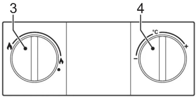
fig. 1 - Control panel
3 Burner power adjustment
4 Temperature adjustment
1.3 Turning the heater on and off

When the unit is working, the temperature near the peephole may be high. Avoid contact as there may be risk of burns.
Preliminary checks and operations
1 Make sure the hot water taps are closed.
2 Open the gas supply cock to the heater, located at the gas connection to the unit.
3 Check that the 1.5V batteries are properly installed with the correct polarity (+/-) . To replace the batteries, see (3.4 Replacing the batteries).
4 Also verify that the batteries are sufficiently charged for heater operation.
1.3.1 Turning the unit on
Turn the knob to the required water heating level.
The unit will begin operating every time hot water is drawn.
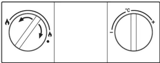
fig. 2 - Turning the unit on
1.3.2 Turning the unit off
The burner goes off automatically when hot water is no longer demanded.
To use the unit again, no action is required.
To completely shut off the unit, place the knob in the () position.
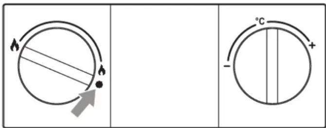
fig. 3 - Turning the unit off
If the water heater will not be used for an extended period of time, close the gas cock supplying the unit.

If the unit will be inactive for an extended period of time during the winter, all water should be removed to avoid ice damage.
1.4 Settings
1.4.1 Setting the burner power manually
Use the knob (3 fig. 1) to select the heater power. You may choose between the minimum, maximum, and intermediate positions, depending on the required heating power.
If the knob is turned counterclockwise, the unit will operate at maximum power. If the temperature is too high, for example in the summer, or if you need a reduced flow of not very hot water, turn the knob clockwise. This reduces the power, and therefore the gas consumption. In the position, the unit is turned off.
1.4.2 Setting the temperature
Turn the water temperature selector clockwise to increase the temperature, or counterclockwise to decrease it.
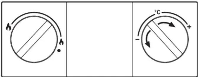
fig. 4 - Setting the temperature
1.5 Faults
Once the adjustments described above have been made, the heater is ready to operate automatically. When a hot water tap is opened, an intermittent discharge is generated on the ignition electrode to light the burner.
All electronic models have an ionization electrode built into the burner to monitor flame presence. If a malfunction or lack of gas causes the heater to turn off, close the hot water tap.
It is then necessary to eliminate the fault or obstacle preventing the gas from reaching the heater, e.g., inadvertent closing of the gas cock, empty gas cylinder, etc.
To reactivate the heater, close and open the hot water tap.
If no hot water is produced after eliminating the cause and opening the hot water tap, repeat the process.
If the problem persists, call the technical support center.
Table 1 - Faults
| The burner does not ignite | Absence of gas | Check the flow of gas to the heater, and make sure the pipes have been purged. |
| Failure of the ignition/detection electrode | Check the electrode cable, and make sure it's properly connected and free of deposits. | |
| Defective gas valve Check and/or change the gas valve. | ||
| Activation of the over-temperature protection | Damaged or badly positioned heating sensor | Check that the heating sensor is properly installed and operating and/or change it. |
| Activation of the flue gas thermostat (after this operation, the unit is reset by turning on the tap, and the thermostat cools off). | Flue gas thermostat contact open Check the thermostat. | |
| Cables disconnected Check the connections. | ||
| Thermostat obstructed or incorrectly sized | Check the thermostat. | |
| Probe disconnected Check the connection or change the probe. | ||
2 INSTALLATION MANUAL
2.1 General information

The heater may only be installed by an authorized technician, in accordance with all instructions contained in this manual, standard UNE 26, and local installation and exhaust regulations.
2.2 Location
Make sure the water heater chosen is the most suitable:
- To adequately meet the system's hot water requirements.
- For the gas to be used (see water heater dataplate).
- For the water supply pressure, necessary for operation (see table of characteristics).
Make sure the room where the unit is installed meets all the requirements of the Current Regulations. In particular, this unit is an "open chamber" type and must only be installed and operate in permanently ventilated places. An insufficient supply of combustion air will compromise normal operation and the evacuation of fumes. Also, the fumes forming under these conditions are extremely harmful to health if dispersed in the domestic environment. Otherwise there may be risk of suffocation and intoxication or explosions and fire.. Therefore the place of installation must be free of dust, flammable materials or objects or corrosive gases.
Position the water heater as close as possible to the hot water taps, near the sink, but NEVER above a cooktop. It must also be situated as close as possible to the flue or the start of the flue gas exhaust pipe.
If the unit is installed inside a cabinet or joined laterally to other elements, space must be allowed for removing the casing and performing normal maintenance activities.
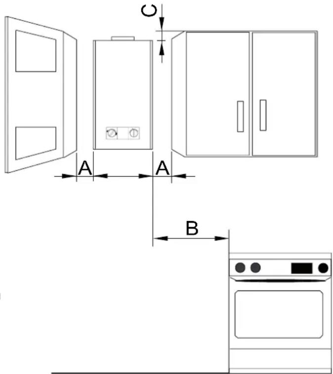
fig. 5 - Minimum distances
| A | On each side | >2cm |
| B- >50cm | ||
| C | In front | >2cm |
2.3 Assembling the heater

Before assembling the heater, make sure the water and gas connections are properly secured, identified, and positioned.
See the dimensions and connections in section 4.2.
Fix the plugs and hooks on the wall, in a central position vertical to the appliance, as shown in the figure below.
- Mark the position of the bottom screws
- Hang the water heater on the plugs+hooks and tighten the screws for fixing the unit to the wall.
- Connect the hot and cold water flexible tubes, remembering to check their tightness. To avoid circulation problems, do not remove the cold water inlet filter.
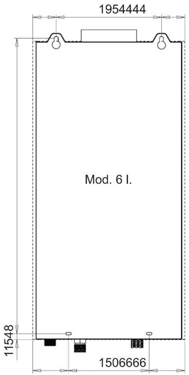
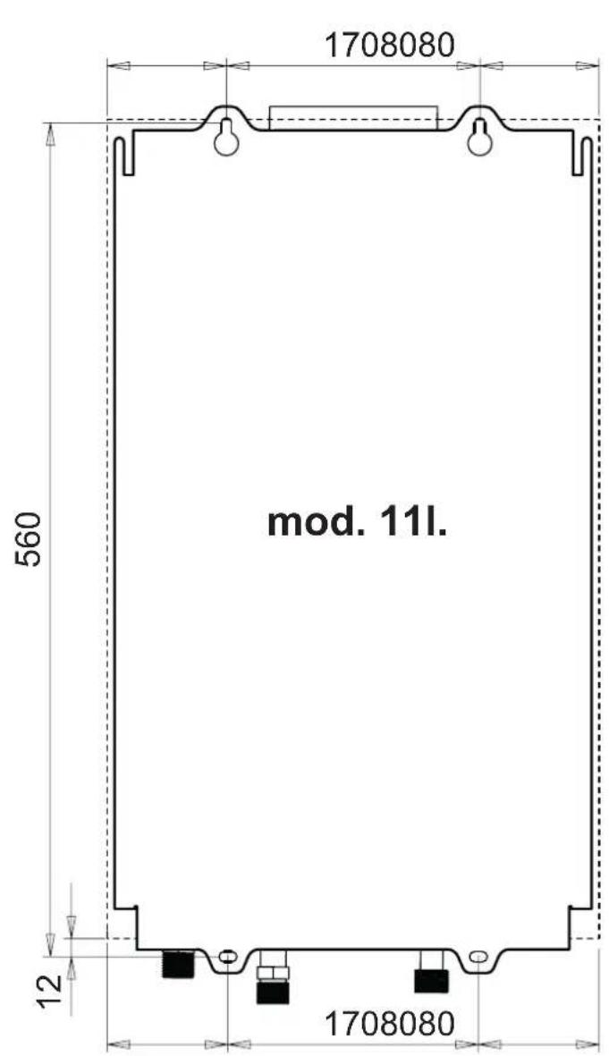
fig. 6 - Assembly template
- Verify all documents.
- Remove the plugs from the water and gas connections (see fig. 8).
- On the rating label, check the destination country reference and the type of gas for which the unit is supplied.
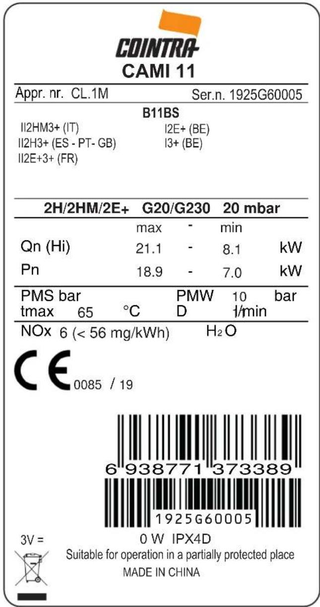
fig. 7 - Rating label
2.4 Hydraulic connections

Never support the water heater by the water/gas connections. Make the connections in accordance with the dimensions and connections shown in section 4.1.
There are labels on the unit identifying the 1/2 water inlet pipe (Red and blue label) and the 1/2 gas inlet pipe (yellow label).
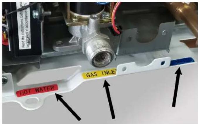
fig. 8 - Connection cards
If the water hardness is over 25^ (1^ = 10ppm CaCO3), the water must be treated to avoid possible deposits on the unit.
2.4.1 Water flow rate adjustment
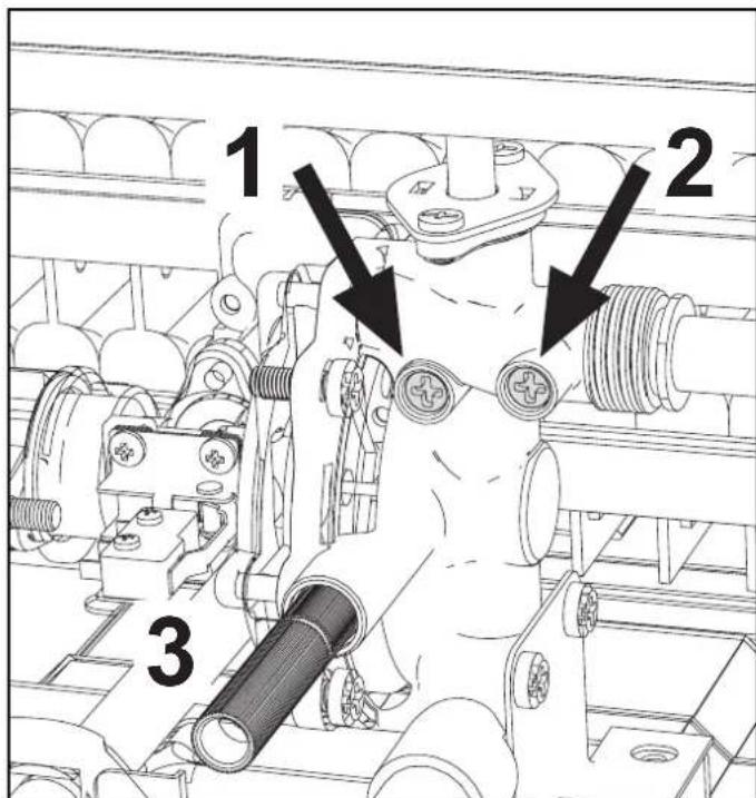
Fig. 9 - Water flow adjustment screws
Legend
1 - Minimum water flow regulation screw.
2 - Maximum water flow adjustment screw.
3 - Safety valve drain water.
2.5 Gas connection

Before making the connection, check that the unit has been prepared to operate with the right type of fuel, and carefully clean the gas pipes to remove any residue that might hinder correct operation. Make this connection in accordance with the dimensions and connections in section 4.1.
1 Connect the corresponding gas inlet (see section 4.2) in accordance with current regulations in the country where the heater is being installed.
2 Connect using a rigid metal pipe (connection to a gas supply network) or a flexible, continuous stainless steel pipe (LPG installation), adding a shut-off valve between the installation and the unit (AS CLOSE TO THE UNIT AS POSSIBLE).
3 Once the connection to the gas network is complete, check that all gas connections are tight. For this purpose, a tightness test must be performed. To avoid damage to the unit due to excess pressure, leave the gas inlet valve closed.
4 Check that the supplied pressure and gas delivery values are those indicated for the unit's consumption. See the technical data table (section 4.5).

In installations with an approved flexible pipe for LPG, pay special attention to the following.
- The pipe must comply with applicable regulations.
- Avoid areas with heat emissions.
- Prevent the pipe from bending or being pinched shut.
- The connections on both sides (gas valve and other components) must comply with the regulations of the country where the heater is installed.
2.6 Air and flue gas ducts
The diameter of the pipe connecting to the flue must not be smaller than that of the pipe connecting to the draft hood. After the draft hood, there must be a vertical segment at least half a meter long. The dimensions and installation of the flues and the tube connecting to them must comply with current standards.
2.6.1 FUME EXHAUST SAFETY DEVICE (fume thermostat)
- The water heater's safety device ensures the correct exhaust of flue gases; THEREFORE DO NOT DEACTIVATE IT OR CARRY OUT ANY OPERATION ON IT.
- If the safety device cuts in when the water heater is started, check the flue gas outlet, checking the exhaust with a cold mirror or with any suitable and approved measuring device.
- In case of a fault, only use original replacements, otherwise the safety device may not work properly.
-
Fume thermostat replacement must be carried out by qualified technicians, proceeding as follows:
-
- Remove the faulty fume thermostat by undoing the 2 fixing screws.
-
- Install a new original thermostat.
-
- Fix the fume thermostat in its place without overtightening the screws.
-
- Check its correct operation.

Remember to make an air inlet opening in the room where the water heater is installed (as required by the current regulations).
If the above instructions are not observed there may be risk of suffocation or poisoning due to gas or fumes escaping.
3 SERVICE AND MAINTENANCE
All of the adjustments, commissioning operations and periodic checks described below must be performed by an authorized technician in compliance with current regulations. FERROLI declines all liability for property damage or injuries caused by unauthorized persons tampering with the unit.
3.1 ADJUSTMENTS
3.1.1 Gas conversion

Conversion of the unit to a type of gas other than the factory setting must be performed by an authorized technician, using original components and in compliance with current regulations in the country where the unit will be used.
The unit can operate with methane gas, LPG or Propane-Air. It is factory-set for one of the two types of gas, as indicated on the packaging and technical data plate. To operate the unit with another type of gas, a conversion kit must be used.
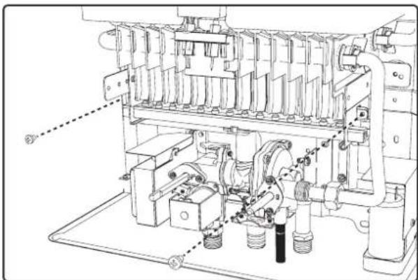
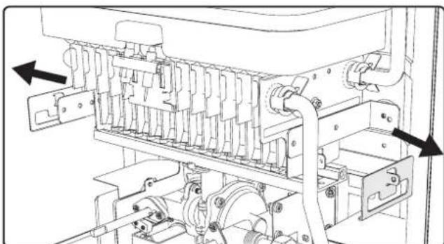
fig. 10 -
fig.11-
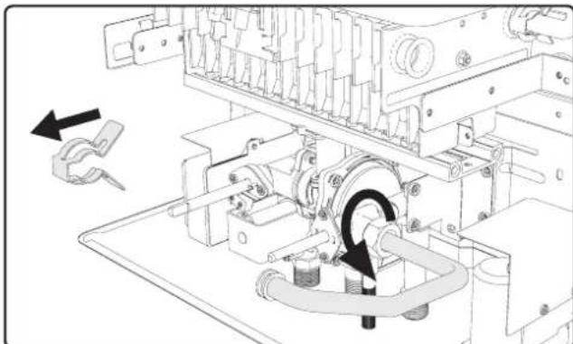
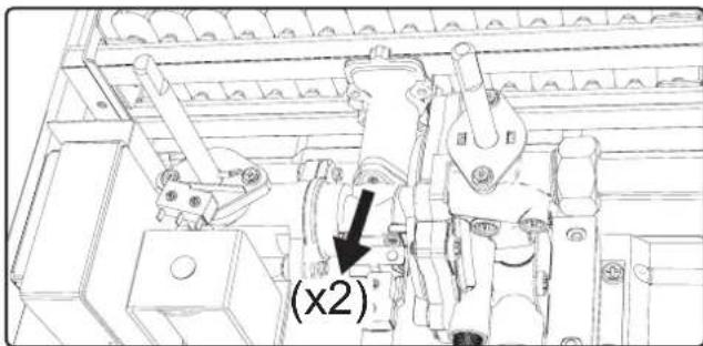
fig. 12 -
fig.13-
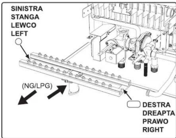
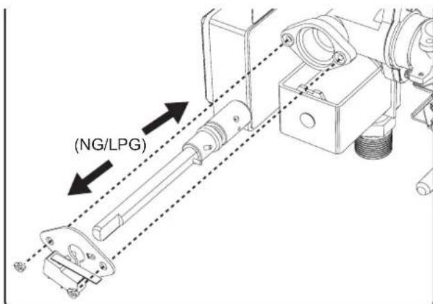
fig. 14 -
fig. 15 -
3.2 COMMISSIONING

Commissioning of the heater must be performed by a trained, specialized technician.
Checks that must be performed during the first ignition, after maintenance operations that require unplugging the unit, and after any operations on the unit's safety devices or components.
3.2.1 Before igniting the heater
- Carefully verify the tightness of the gas installation using a soap and water solution to check for leaks in the connections.
- Fill the hydraulic system and make sure no air is present in the unit or system.
- Check that there are no water leaks in the system or unit.
- Make sure the grounding and connection to the electrical network are adequate.
- Check that the gas pressure is correct.
- Make sure there are no flammable liquids or materials near the heater.
- To avoid damaging the connections, do not place the heater on the floor with the connections facing down.

If the above instructions are not observed there may be risk of suffocation or poisoning due to gas or fumes escaping; danger of fire or explosion. Also, there may be risk of flooding the room.
3.2.2 Checks during operation
Light the unit.
Make sure the fuel and water systems are tight.
- Check the efficiency of the air and flue gas ducts while the heater is operating.
- Make sure the gas valve modulates correctly.
- Verify that the heater ignites easily. Turn it on and off several times to make sure.
- Check that the fuel consumption is as indicated.
3.3 MAINTENANCE
3.3.1 Periodic checks
In order for the unit to operate correctly, an authorized technician must perform an annual inspection, checking that:
- The control and safety devices (gas valve, etc.) operate correctly.
- The exhaust vent is perfectly efficient.
- The air and flue gas ducts and terminal are free of obstacles and leaks.
- The burner and exchanger are free of dirt and deposits. Do not use chemicals or steel brushes to clean them.
- The electrode is free of deposits and properly positioned.
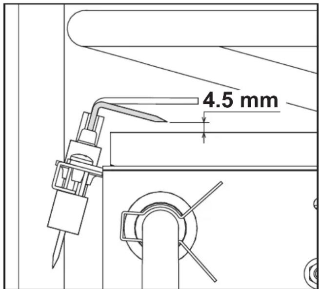
fig. 16 - Electrode position
- The gas and water systems are perfectly tight.
- The gas delivery and operating pressure values are as indicated on the tables.
A soft, damp cloth may be used to clean the casing and exterior parts of the heater, using soapy water if necessary. Do not use abrasive detergents or solvents.
3.3.2 Opening the casing

Before performing any operations inside the heater, close the gas cock.
To open the casing:
1 Unscrew the A screws.
2 Rotate the casing.
3 Lift the casing.
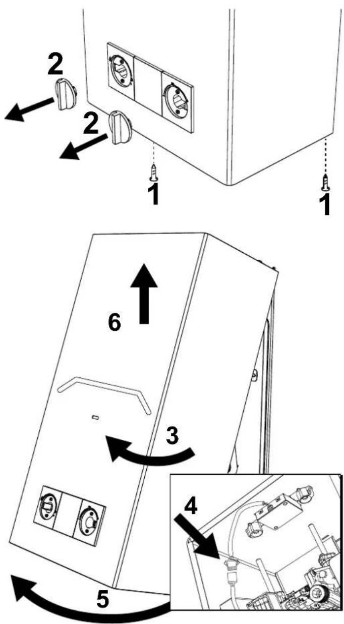
3.4 REPLACING THE BATTERIES
To change the batteries, proceed as described in fig. 18.
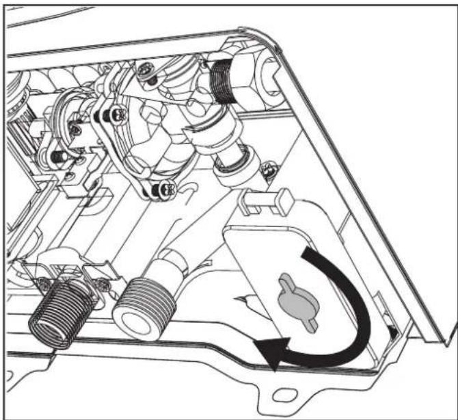
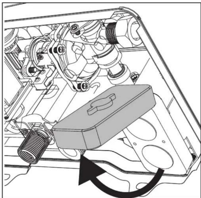
fig. 18 - Opening the battery box
fig. 17 - Opening the casing
4 TECHNICAL DATA AND CHARACTERISTICS
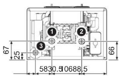
4.1 Dimensions and connections
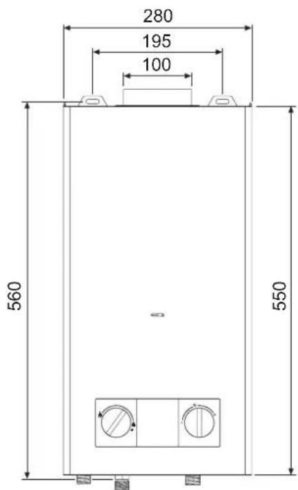
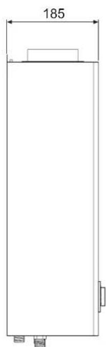
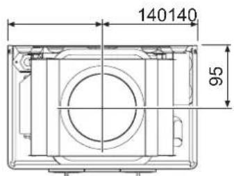
fig. 19 - Dimensions and connections CAMI 6
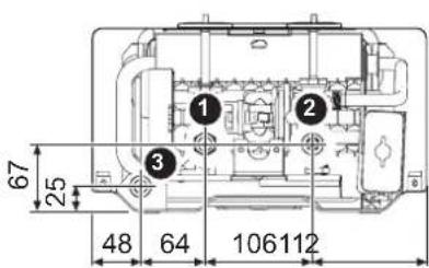
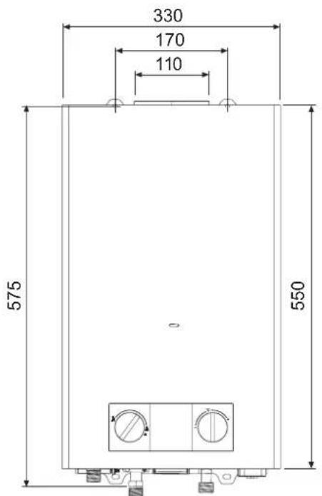
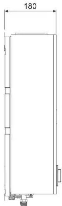
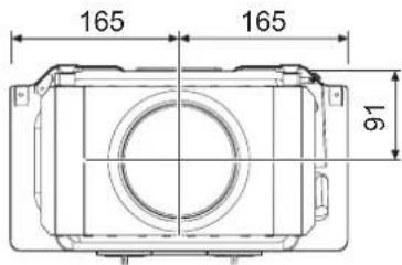
fig. 20 - Dimensions and connections CAMI 11
1 1/2" gas inlet
2 1/2" cold water inlet
3 1/2" domestic hot water outlet
4.2 Overview and main components
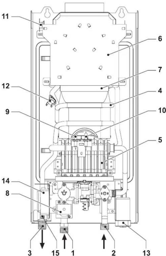
fig.21-Overview CAMI 6
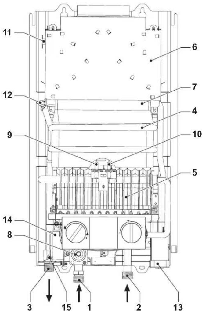
fig.22-Overview CAMI 11
1 Gas inlet
2 Cold water inlet
3 Hot water outlet
4 Combustion chamber assembly
5 Gruppo bruciatori
6 Exhausthood
7 Copper heat exchanger
8 Solenoid valve
9 Induction electrode
10 Ignition electrode
11 Flue gas sensor
12 Hot water temperature sensor
13 Battery pack
14 Pulser
15 DHW temperature sensor
4.3 Hydraulic circuit
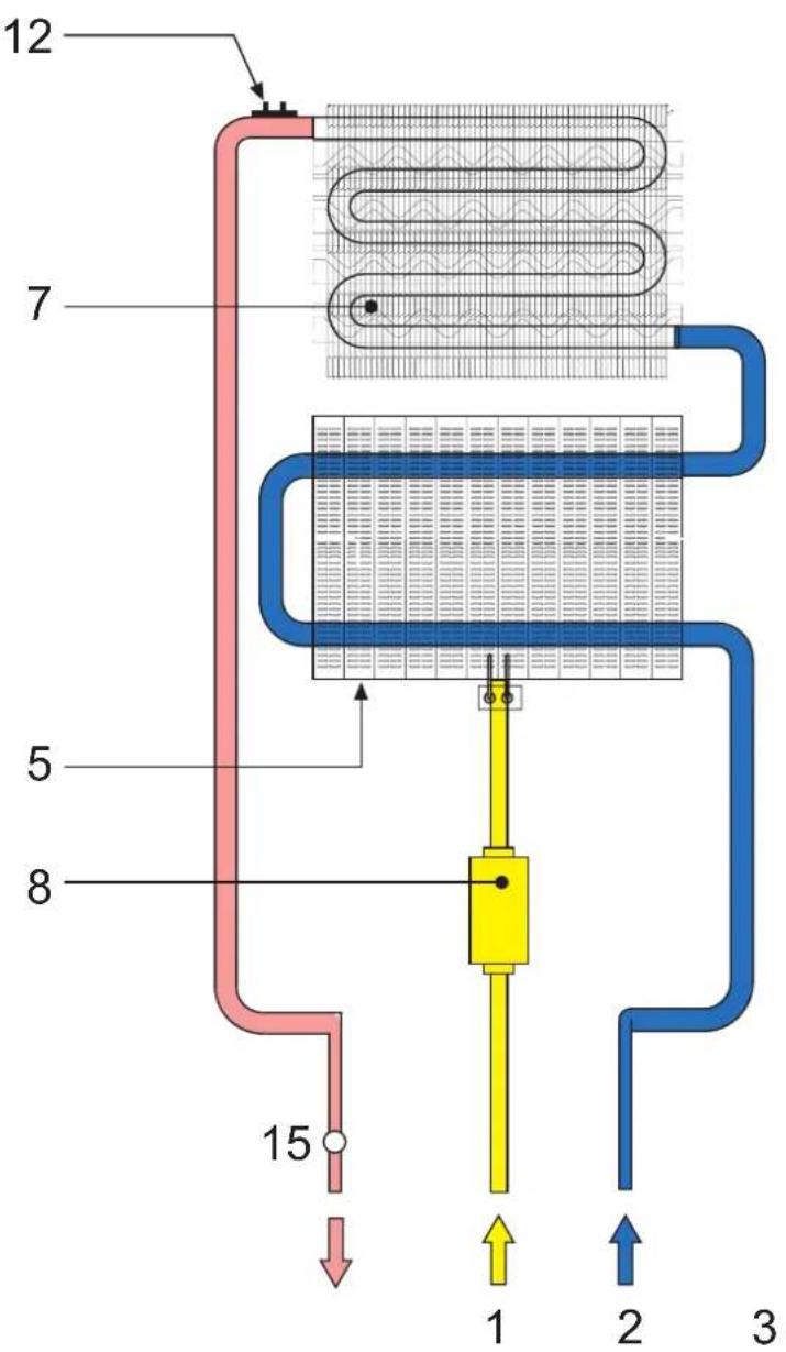
fig. 23 - Hydraulic circuit
1 Gas inlet
2 Cold water inlet
3 Hot water outlet
5 Gruppo bruciatori
7 Copper heat exchanger
8 Solenoid valve
12 Hot water temperature sensor
15 DHW temperature sensor
4.4 Technical data table
| Data | Units | CAMI 6 CAMI 11 | ||
| Product identification codes G20 | GCA1HFKF GCA1MFKF | |||
| Product identification codes G31 | GCA1HGKF GCA1MGKF | |||
| Countries of destination | ES-PT-IT-FR-BE | |||
| Gas category | II2H3+(ES-PT-GB)/II2HM3+(IT)/II2E+3+(FR)/I2E+(BE)/I3+(BE) | |||
| Maximum heat capacity | kW 11.8 | 21.1 Q | ||
| Minimum heat capacity | kW 6.3 | 8.1 Q | ||
| Maximum heat capacity | kW 10.4 | 18.9 | ||
| Minimum heat capacity | kW 5.4 | 7.0 | ||
| Performance at max. power | % 87.87 | |||
| Burner injectors G20 | n.xØ 14 | x 0.82 | 24 | x 0.85 |
| Gas supply pressure G20 | mbar 20 | 20 | ||
| Maximum gas delivery G20 | m3/h | 1.25 | 2.23 | |
| Minimum gas delivery G20 | m3/h | 0.67 | 0.86 | |
| Burner injectors G230 | n.xØ 14 | x 0.95 | 24 | x 0.95 |
| Gas supply pressure G230 | mbar 20 | 20 | ||
| Maximum gas delivery G230 | m3/h | 0.97 | 1.73 | |
| Minimum gas delivery G230 | m3/h | 0.52 | 0.66 | |
| Burner injectors G31/G30 | n.xØ | 8 x 0,49 / 6 x 0,47 | 18 x 0.49 / 6 x 0.47 | |
| Gas supply pressure G31/G30 | mbar | 37 / 29 | 37 / 29 | |
| Max. gas delivery G31/G30 | m3/h | 0.92 | 1.64 | |
| Min. gas delivery G31/G30 | m3/h | 0.49 | 0.63 | |
| NOx emission class | - | 6 (<56 mg/kWh) | ||
| Max. operating pressure | bar 10 10 | PMS | ||
| Min. operating pressure | bar | 0.2 | 0.2 | |
| DHW delivery Δ25° | l/min | 6.0 | 10.8 | |
| DHW delivery Δ30° | l/min | 5.0 | 9 | |
| Degree of protection | IP | X4D | ||
| Supply voltage | V/Hz | 3V= | ||
| Absorbed electrical power | W | / | / | |
| Empty weight | Kg | 8.5 | 9.50 | |
| Type of unit | B11BS | |||
| ErP product fiche (Models NG) | |||
| Trademark: COINTRA | |||
| Type: Conventional water heater | |||
| Item Symbol Unit Value | |||
| CAMI 6GCA1HFKF | CAMI 11GCA1MFKF | ||
| Declared load profile | XS | M | |
| Water heating energy efficiency class (from A+ to F) | A+ | A | |
| Daily electricity consumption | Qelec kWh/annum | 0,000 0,000 | |
| Annual electricity consumption | AEC kWh | 0 | 0 |
| Water heating energy efficiency | NWh % | 58 76 | |
| Daily fuel consumption | Qfuel kWh | 2,874 8,185 | |
| Annual fuel consumption | AFC GJ/ annum | 3 | 7 |
| Thermostat temperature settings of the water heater, as placed on the market | MÁX. MÁX. | ||
| Sound power level | LWA dB | 57 58 | |
| Emissions of nitrogen oxides | NOx mg/kWh | 52 37 | |
| ErP product fiche (Models LPG) | |||
| Trademark: COINTRA | |||
| Type: Conventional water heater | |||
| Item Symbol Unit Valore | |||
| CAMI 6GCA1HGKF | CAMI 11GCA1MGKF | ||
| Declared load profile | XS | M | |
| Water heating energy efficiency class (from A+ to F) | A+ | A | |
| Daily electricity consumption | Qelec kWh/annum | 0,000 0,000 | |
| Annual electricity consumption | AEC kWh | 0 | 0 |
| Water heating energy efficiency | NWh % | 58 76 | |
| Daily fuel consumption | Qfuel kWh | 2,874 8,185 | |
| Annual fuel consumption | AFC GJ/ annum | 3 | 7 |
| Thermostat temperature settings of the water heater, as placed on the market | MÁX. | MÁX. | |
| Sound power level | LWA dB | 57 58 | |
| Emissions of nitrogen oxides | NOx mg/kWh | 37 58 | |
4.5 Wiring diagram
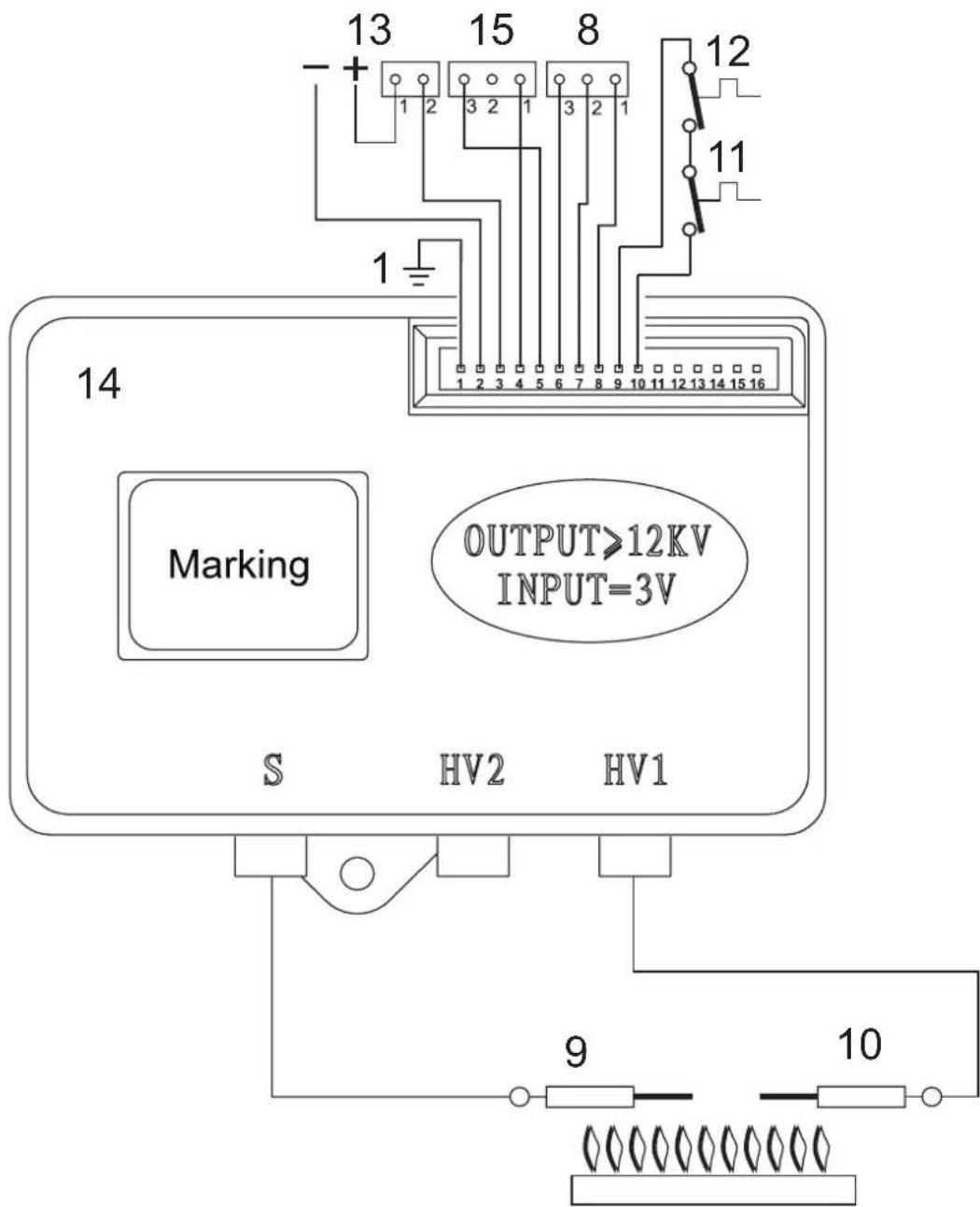
fig.24 -
Key
8 Gas valve
9 Detection electrode
10 Ignition electrode
11 Safety thermostat
12 Contact fume thermostat
13 Batteries
14 Electronic controller
15 Flow switch
AVVERTENZE GENERALI


- ASSISTÊNCIA E MANUTENÇA
- USER'S MANUAL
- Introduction
- Control panel
- Turning the heater on and off
- Preliminary checks and operations
- Turning the unit on
- Turning the unit off
- Settings
- Setting the burner power manually
- Setting the temperature
- Faults
- INSTALLATION MANUAL
- General information
- Location
- Assembling the heater
- Before assembling the heater, make sure the water and gas connections are properly secured, identified, and positioned.
- See the dimensions and connections in section 4.2.
- Hydraulic connections
- Water flow rate adjustment
- Legend
- Gas connection
- Air and flue gas ducts
- FUME EXHAUST SAFETY DEVICE (fume thermostat)
- SERVICE AND MAINTENANCE
- ADJUSTMENTS
- Gas conversion
- COMMISSIONING
- Before igniting the heater
- Checks during operation
- MAINTENANCE
- Periodic checks
- Opening the casing
- Before performing any operations inside the heater, close the gas cock.
- REPLACING THE BATTERIES
- TECHNICAL DATA AND CHARACTERISTICS
- Overview and main components
- Hydraulic circuit
- Wiring diagram
- AVVERTENZE GENERALI
Brand : COINTRA
Model : Cami
Category : Boiler