
CETI 15-N - Boiler COINTRA - Free user manual and instructions
Find the device manual for free CETI 15-N COINTRA in PDF.

| Product type | Sealed gas water heater |
| Brand | COINTRA |
| Model | CETI 15-N |
| Category | Boiler (domestic hot water production) |
| Usage | Domestic |
| Power supply | 230 V - 50 Hz |
| Power consumption | 36 W |
| Gas supply | Natural gas (G20) or LPG (G30/G31) |
| Maximum thermal power (Hi) | 29.7 kW |
| Minimum thermal power (Hi) | 4 kW |
| DHW flow rate at ΔT 25°C | 15.5 L/min |
| Adjustable temperature range | 30 °C to 65 °C |
| Operating pressure | 0.2 to 10 bar |
| Net weight | 14.5 kg |
| Dimensions (H x W x D) | 700 x 400 x 250 mm (approximate) |
| Protection rating | IPX4D |
| Flue type | Coaxial or separate (type C) |
| ECO mode | Yes (power limited to 80%) |
| Solar function | Yes (configurable) |
| Periodic maintenance | Annual by authorized technician |
| Warranty | 2 years |
| Certifications | CE (0085/22) |
| Number of injectors (G20) | 16 x 0.75 mm |
| Energy efficiency class | A |
| Declared load profile | XL |
Frequently Asked Questions - CETI 15-N COINTRA
User questions about CETI 15-N COINTRA
0 question about this device. Answer the ones you know or ask your own.
Ask a new question about this device
Download the instructions for your Boiler in PDF format for free! Find your manual CETI 15-N - COINTRA and take your electronic device back in hand. On this page are published all the documents necessary for the use of your device. CETI 15-N by COINTRA.
USER MANUAL CETI 15-N COINTRA
CE
ES INSTRUCCIONES TÉCNICAS E INSTRUCCIONES DE USO
PT INSTRUÇÕES TÉCNICAS E INSTRUÇÕES DE USO
FR INSTRUCTIONS TECHNIQUES ET INSTRUCTIONS D'UTILISATION
EN TECHNICAL INSTRUCTIONS AND INSTRUCTIONS FOR USE
ESPAÑOL 4
PORTUGUÊS 22
FRANÇAIS 40
ENGLISH 58
1.5 FUNCIONAMIENTO
natural_image
Technical diagram of a mechanical assembly with labeled components (no readable text or symbols)natural_image
3D rendering of a white cylindrical mechanical component with mounting holes and a side clip (no text or symbols visible)- Para conexión tubo coaxial vertical adaptado de ∅ 60/100 a ∅ 80/125 (V010038X0):
natural_image
3D rendering of a white mechanical component with cylindrical and rectangular features, mounted on a flat base (no text or symbols visible)natural_image
3D rendering of a white robotic arm mounted on a rectangular base with circular components (no text or symbols visible)natural_image
3D rendering of a white plumbing outlet with two cylindrical fixtures and a base plate (no text or symbols visible)natural_image
Exterior view of a white industrial refrigerator with a small label and arrow indicator (no readable text or symbols)3.4 ERRORES
natural_image
Technical diagram of a cylindrical mechanical component with hatched side and mounting base (no text or symbols)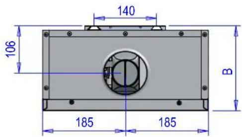
| Modelo | A(mm) | B(mm) | C(mm) | Conexiones | ||
| Agua Fría | Agua Caliente | Gas | ||||
| CETI 10 | 370 | 190 | 525 1/2” | |||
| CETI 12 | ||||||
| CETI 15 | ||||||
| CETI 17 | ||||||
1.5 FUNCIONAMENTO
natural_image
Technical diagram of a mechanical assembly with labeled components (no readable text or symbols)natural_image
3D rendering of a white cylindrical mechanical component with mounting holes and a small attached bracket (no text or symbols visible)natural_image
3D rendering of a white mechanical component with cylindrical and rectangular features, mounted on a flat base (no text or symbols visible)natural_image
Mechanical robotic arm mounted on a white base with a metallic shaft (no text or symbols visible)natural_image
3D rendering of a white industrial pipe fitting with two cylindrical cavities and a base plate (no text or symbols visible)natural_image
Exterior view of a white industrial refrigerator with a door and label (no visible text or symbols)3.4 ERROS
natural_image
Technical diagram of a cylindrical mechanical component with hatched side and mounting base (no text or symbols)
1.5 FONCTIONNEMENT
natural_image
Technical diagram of a mechanical assembly with mounting holes, fittings, and a lever (no text or symbols)natural_image
3D rendering of a white cylindrical mechanical component with mounting holes and a side-mounted bracket (no text or symbols visible)natural_image
3D rendering of a white cylindrical mechanical component with mounting flanges and mounting holes (no text or symbols visible)natural_image
3D rendering of a white industrial robotic arm mounted on a rectangular base (no text or symbols visible)natural_image
3D rendering of a white industrial pipe fitting with two cylindrical components and mounting base (no text or symbols visible)natural_image
Exterior view of a white industrial refrigerator with a small label and arrow indicator (no readable text or symbols)3.4 ERREURS
natural_image
Technical diagram of a cylindrical mechanical component with mounting base and side hatching (no text or symbols)
| Modèle | A(mm) | B(mm) | C(mm) | Raccordements | ||
| EauFroide | EauChaude | Gaz | ||||
| CETI 10 | 370 | 190 | 525 1/2” | |||
| CETI 12 | ||||||
| CETI 15 | ||||||
| CETI 17 | ||||||
- Please read the warnings in this instruction booklet carefully, as they provide important information on installation, use and maintenance.
- This instruction booklet is an integral and essential part of the product and the user must store it carefully so it can be consulted whenever necessary.
- If the unit is sold or given to another owner or if its location is changed, the manual must go with it so the new owner or installer can consult it.
- Installation and maintenance must be performed by an authorized technician, in compliance with applicable regulations and the manufacturer's instructions.
- Incorrect installation or inadequate maintenance can cause personal injury or material damage. The manufacturer does not accept any liability for damage caused by errors in installation and use or by failure to follow the instructions provided.
- Before doing any cleaning or maintenance work, disconnect the unit from the power supply using the system switch or another cut-off device.
- In the event of a fault or malfunction, disconnect the unit and only have it repaired by an authorized technician.
Only use professionally qualified personnel. Repairs and component replacements may only be carried out by authorized technicians using original replacement parts. Failure to comply with the above may compromise the safety of the unit.
- Regular maintenance performed by qualified personnel is essential to ensure proper operation of the unit.
- This unit must only be used for its intended purpose. Any other use is considered inappropriate and therefore dangerous.
- Unpack the unit and check that it is in perfect condition. The packing materials are a potential source of danger, and must be kept out of reach of children.
- The unit can be used by children aged 8 years and over and by persons with impaired physical, sensory or mental abilities or lacking experience or the necessary knowledge, provided they are supervised and instructed in its safe use and they understand the hazards associated with its use. Children must not play with the unit. The unit's cleaning and maintenance to be done by the user can be performed by children aged 8 and over if they are supervised
at all times.
- If in any doubt, do not use the unit and consult your supplier.
- Dispose of the unit and its accessories in compliance with applicable regulations.
- The images included in this manual are a simplified representation of the
product. This representation can have slight and insignificant differences vis-a-vis the product supplied.
- UNIT FOR DOMESTIC USE, NOT SUITABLE FOR INDUSTRIAL USE
| This symbol means “Caution,” and is displayed next to safety warnings. Observe these warnings strictly to prevent dangerous situations or injury/damage to people, animals and materials. | |
| This symbol refers to information that does not include hazards for people or materials. |

The CE marking certifies that products meet the fundamental requirements of the applicable European directives. The declaration of conformity can be requested from the manufacturer.
INDEX
1 INSTRUCTIONS FOR USE....61
1.1 Presentation 61
1.2 Display symbols 61
1.3 Control panel keys....61
1.4 Control Panel....61
1.5 OPERATION....61
1.5.1 ON and OFF....62
1.5.2 NORMAL Operation 62
1.5.2.1 Temperature Setting....62
1.5.2.2 Domestic Hot Water 62
1.5.3 ECO mode....62
1.5.3.1 Enabling ECO mode 62
1.5.3.2 Temperature Setting in ECO mode 62
1.5.3.3 Disabling ECO mode....62
1.5.4 Solar Energy Function....62
2 INSTALLATION INSTRUCTIONS....63
2.1 General instructions 63
2.2 Installation location....63
2.3 Installing the water heater 63
2.4 Hydraulic connections 64
2.5 Gas connection 64
2.6 Electrical connections....65
2.7 Air and flue gas ducts 65
2.7.1 Connection with coaxial pipes....65
2.7.2 Connection with separate pipes 66
3 SERVICE AND MAINTENANCE....67
3.1 ADJUSTMENTS 67
3.1.1 Gas conversion 67
3.1.2 Gas valve calibration....68
3.2 COMMISSIONING 69
3.2.1 Before turning the water heater on....69
3.2.2 Checks during operation 69
3.3 MAINTENANCE 69
3.3.1 Regular check 69
3.3.2 Opening the casing 70
3.4 ERRORS....70
3.4.1 Error list....70
3.4.2 Error History 70
3.5 PARAMETERS....70
3.5.1 Parameter list 71
4 CHARACTERISTICS AND TECHNICAL DATA 72
4.1 Dimensions and connections 72
4.2 Overview and main components....73
4.3 Technical Data Table 74
4.4 Electrical diagram....75
1 INSTRUCTIONS FOR USE
1.1 Presentation
The new CETI is a COMPLETELY SEALED high-performance water heater with low environmental pollution emissions for providing domestic hot water, supplied with Natural Gas or LPG and fitted with a latest technology burner, with high modulation, which reduces the emission of pollutant gases and provides stable and precise combustion. It also includes a fan that works in combination with the burner, and from an intuitive and touch-sensitive microprocessor control system. This water heater can also work together with solar panels.
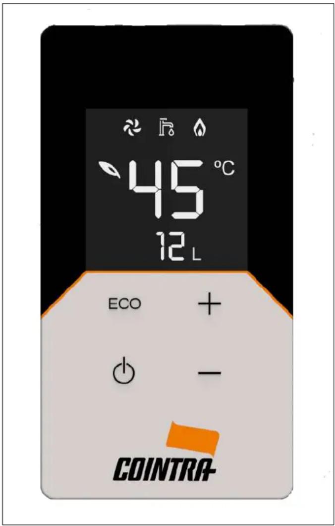
1.2 Display symbols
| SYMBOL DESCRIPTION | |
 | FLAME: This symbol lights when the burner is on. |
 | TAP: This symbol lights when water flows through the unit. |
 | FAN: This symbol lights when the fan's motor is on. |
 | ECO: This symbol lights when the ECO function is enabled. |
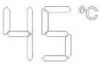 | TOP DIGITS:1. Water temperature (shows the real temperature of the water outlet by default)2. Temperature setpoint (touching the + / - keys)3. Error codes4. Value of each parameter |
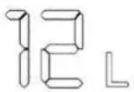 | BOTTOM DIGITS:1. Water flow2. Reference Parameters |
1.3 Control panel keys
| SYMBOL DESCRIPTION | |
| ECO | ECO Function: This key is used to enable/ disable the ECO mode. |
| STANDBY: This key is used to put the unit into STANDBY mode and/or OPERATIONAL mode. | |
| + | These keys change the temperature setpoint, both NORMAL and ECO, and the internal parameters. |
| - | |
1.4 Control Panel
1.5 OPERATION
This Gas Water Heater OPERATES as follows:
• STANDBY (in Stand-by Mode)
- OPERATIONAL:
- NORMAL Mode
• NORMAL Mode with support from Thermal Solar Energy - ECO Mode
• ECO Mode with support from Thermal Solar Energy
1.5.1 ON and OFF
From the STANDBY mode, by touching the Standby key the unit becomes OPERATIONAL, turning the display on. From OPERATIONAL state, by touching the Standby key the unit goes to STANDBY mode, turning the display off. In both cases an acoustic signal confirms each action.
In STANDBY mode the burner does not start when a tap is opened.
1.5.2 NORMAL Operation
The water heater's NORMAL operation instantly provides domestic hot water at the required temperature and set by the user. When the water heater's normal operation is activated, the real water outlet temperature is shown, and the symbol is turned off.
1.5.2.1 Temperature Setting
The outlet water temperature can be set with the “+” and “-” keys.
The NORMAL temperature setting is between 35 °C and 50 °C (the maximum value, initially 50 °C, can be changed via the nS parameter, see Section 3.5). The normal temperature setting is 50 °C by default.
1.5.2.2 Domestic Hot Water
When the tap is opened and a water flow is detected by the flowmeter, the unit begins to operate, and the symbol lights on the display.
The fan symbol 📋 and the flame symbol 🐵 come on according to the state they are in.
When the tap opens the bottom digits display shows the current water flow rate ( ).
The water heater will heat water continually for a maximum of 60 minutes (value which can be changed via the nE parameter, see Section 3.5), after which it will stop for safety reasons.
1.5.3 ECO mode
This mode is generally used to reduce energy consumption. When this function is enabled the symbol is shown on the top digits display.
In ECO mode the outlet capacity is limited to 80 % of the maximum value, and a separate temperature setting is used.
1.5.3.1 Enabling ECO mode
If this mode is disabled, you must touch the ECO key. The symbol will then light immediately on the display.

During this mode, when opening the tap the burner begins the ignition sequence and when the electrode detects the flame, the unit keeps the burner on and modulating the fan and the gas.
1.5.3.2 Temperature Setting in ECO mode
In this mode the water temperature setpoint can be different to that in the NORMAL mode, but it will never be higher than it. This ECO temperature setting, just like the NORMAL one, can be changed with the “+” and “-” keys.
The ECO temperature setting is therefore between 35 °C and the NORMAL temperature setting. The normal ECO temperature setting is 42 °C by default.
1.5.3.3 Disabling ECO mode
To deactivate this mode, touch the ECO key on the control panel. The symbol goes off.
1.5.4 Solar Energy Function
To operate the water heater together with solar panels and use the solar energy they supply, there are some parameters that define the water heater's behavior. The water heater will only activate when the inlet water temperature, produced by solar energy, is lower than the set temperature.
In the description of parameters (see Section 3.5), "FC" must be on "ON", as there are 3 other key parameters:
S1: Hysteresis to turn the burner on (°C)
S2: Hysteresis to turn the burner off (°C)
t1: Delay time to turn the burner on (seconds)
- When the inlet water T is < (setting T - S1 ), the burner starts the t1 timing, or the time after which the burner ignites.
- When the inlet water T is > (setting T + S2), the burner turns off.
Once the burner has ignited, for the first 30 seconds, to prevent it from continuously going on and off when starting, the control unit automatically increases the turned off T to the setting T + 30 °C.
To change these parameters, S1, S2 and t1, see Section 3.5. Parameter list.
2 INSTALLATION INSTRUCTIONS
2.1 General instructions

The installation must only be performed by an authorized installation technician, as must the electrical, gas and fumes/air exhaust/intake connections respectively, complying with all instructions provided in this manual, the EN 26 standard, as well as the local regulations for installing and venting combustion products.
2.2 Installation location
- The combustion circuit is sealed off from the installation environment, so the unit can be installed in any room. However, the room must be sufficiently ventilated to prevent dangerous situations if there is a gas leak.
- REGULATION (EU) 2016/426 stipulates the safety standards for all installations that work with gas, including those with a sealed chamber.
- The unit can operate in a location partially protected in accordance with the EN 26 standard.
In any case, the unit must be installed in a location free of dust, flammable objects or materials, or corrosive gases.
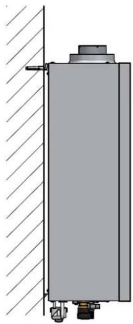
The unit can be installed on the wall:
- Attach to the wall according to the dimensions shown in Section 4.1. The wall installation must be firm and stable.
- Do not install the unit over a heat source.

If the unit is installed inside a closet, for example if it connects laterally to other elements, a space be left to remove the unit's casing and to perform or maintenance work.
![[A] Lateral > 2 cm [B] > 50 cm [C] Front > 2 cm](/content/2026/04/731147/images/53020ae49278b04e18ae9a14bc0afb78f090b3647cac811475c1bc02570097bf.jpg)
2.3 Installing the water heater

Before installing the water heater make sure the water and gas connections are correctly secured, identified and positioned.
See the dimensions and connections in Section 4.1.
1 - The installation template is on the back of the packaging. Cut it out and place it on the wall at the correct height (check distances), making sure that the template is as horizontal as possible (use a level).
2 - Mark the position of the attachment holes.
3 - With a drill and ∅ 8 mm bit, make the attachment holes and attach the expansion plugs.
4 - Remove the unit from the packaging, take out the bag of accessories that comes with the unit, remove the screws and/or attachment hooks and place the unit in its position.
5 - Make sure all the documentation is provided.
6 - Remove the plugs from the water and gas connections.
7 - On the rating plate check the destination country reference and type of gas for which the supplied unit is regulated.
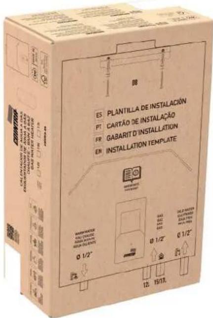
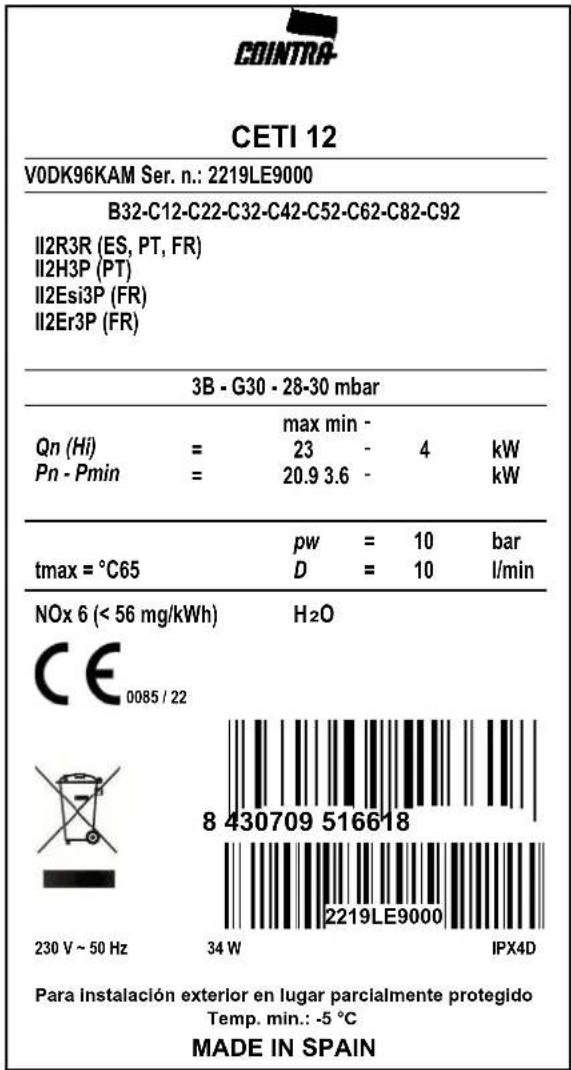
Fig. 1 - Rating plate
2.4 Hydraulic connections
The inlets (water and gas) and water outlet are identified on the bottom of the unit. All are 1/2".
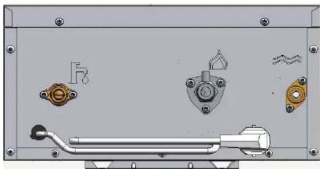
natural_image
Technical diagram of a mechanical assembly with mounting flanges, bolts, and a lever (no text or symbols)| SYMBOL DESCRIPTION | |
 | Symbol for the mains WATER inlet |
 | Symbol for the mains GAS inlet |
 | Symbol for the HOT WATER outlet |
If the water hardness is over 25 °fH (1 °fH = 10 ppm CaCO3), the water must be treated to avoid possible deposits on the unit.
2.5 Gas connection
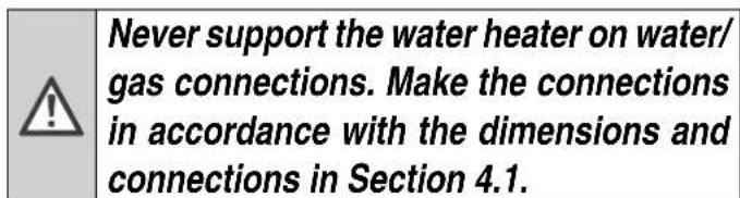
| ! | Before connecting, check that the unit has been prepared for operation with the fuel type and carefully clean all the gas pipes to remove residues that could impair the unit's operation. Make this connection in accordance with the dimensions and connections in Section 4.1. |
- Connect the gas inlet (see Section 4.1) in accordance with the applicable regulations of the country where the water heater is installed.
- Connect with a rigid metal pipe (connection to mains gas supply) or a flexible pipe (approved, do not confuse with flexible elastomer connection) for LPG installation, continuous stainless steel from the wall, adding a shut-off valve between the installation and the unit (AS CLOSE TO THE UNIT AS POSSIBLE).
- After completing the connection to the gas mains, check that all gas connections are tight. For this purpose, a tightness test must be performed. To avoid damage to the unit due to excess pressure, leave the gas inlet valve closed.
Check that the supply pressure and the flow supplied in the unit are those indicated for the unit's consumption.
See and check the Technical Data Table, Section 4.3.

In installations with flexible pipe for LPG (approved, do not confuse with flexible elastomer connection), pay special attention to the following:
- The pipe must comply with applicable regulations.
- Avoid areas with heat emissions.
- Prevent the pipe from bending or being pinched shut.
- The connections on both sides (gas valve and other components) must comply with the regulations of the country where the water heater is installed.
2.6 Electrical connections

The unit's electrical safety must be ensured with grounding, as established by safety standards. Have qualified personnel check the effectiveness of the grounding system, as the manufacturer will not be liable for any damage caused by a lack of grounding on the installation.
The unit's power cable may not be replaced by the user. If the cable is damaged, turn off the unit and call the authorized technical support center to have it replaced.
To replace it use only HAR H05 VV-F cable, 3 x 0.75 mm ^4 with a maximum outer diameter of 8 mm.
2.7 Air and flue gas ducts

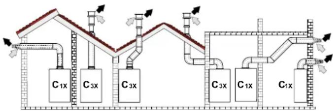
This is a type C unit, with a sealed chamber and forced draft. The air inlet and flue gas outlet must be connected items such as those indicated below.
The unit is approved for operation with all configurations of the Cxy flue shown on the technical data card (some of these are shown as an example below).
It is however possible that some configurations are limited or prohibited by law, standards or local regulations.
Before installing, check and strictly comply with the requirements in question.
Also comply with the provisions for hanging on walls and/or ceilings and the minimum distances to windows, cables, ventilation openings, etc. Section 2.2
2.7.1 Connection with coaxial pipes
flowchart
graph TD
    A["Top Floor"] --> B["C1x"]
    B --> C["C3x"]
    C --> D["C3x"]
    D --> E["Bottom Floor"]
    E --> F["C3x"]
    F --> G["C1x"]
    G --> H["C1x"]
    H --> I["Bottom Floor"]
    I --> J["C1x"]
    style A fill:#f9f,stroke:#333
    style J fill:#f9f,stroke:#333
Fig. 2 - Example of a connection with coaxial pipes
C1x - Horizontal aspiration and evacuation on the wall. C3x - Vertical aspiration and evacuation on the ceiling.

| Coaxial 60/100 | Coaxial 80/125 | |
| Maximum permitted length 4 | m 10 m | |
| Elbow reduction factor 90° 1 m | 0.5 m | |
| Curve reduction factor 45° 0.5 m | 0.25 m |
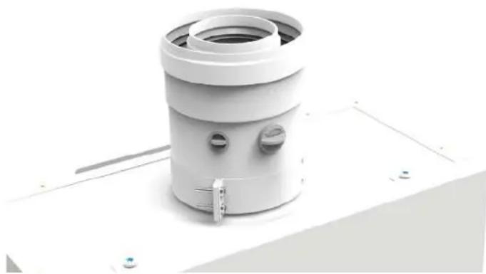
For coaxial connection, install one of the following initial accessories on the unit. For drilling dimensions on the wall, see Section 4.1. Horizontal exhaust segments must slope slightly toward the outside to prevent any condensation from returning to the unit.
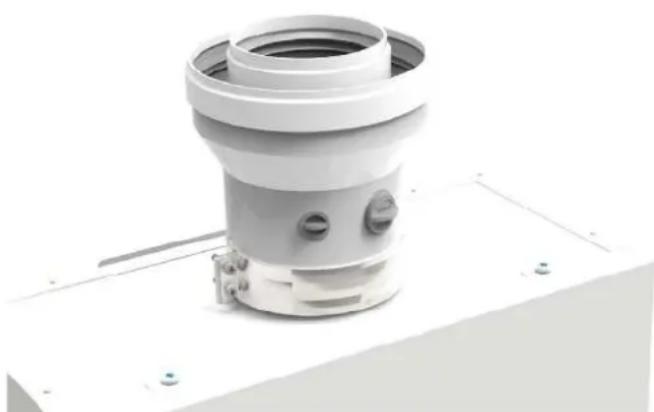
- For coaxial vertical pipe connection ∅ 60/100 (V010037X0):
natural_image
White industrial air vent component with circular ports and a small attached bracket (no text or symbols visible)- For coaxial vertical pipe connection adjusted from ∅ 60/100 to ∅ 80/125 (V010038X0):
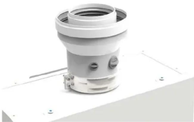
natural_image
3D rendering of a white cylindrical mechanical component with mounting base and side ports (no text or symbols visible)- Aspiration duct Kit / coaxial exhaust For 90° connection + coaxial pipe, ∅ 60/100 (V010040X0):
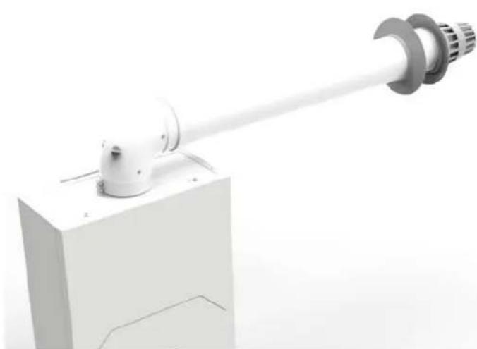
natural_image
3D rendering of a robotic arm mounted on a white base with a cylindrical shaft (no text or symbols visible)2.7.2 Connection with separate pipes
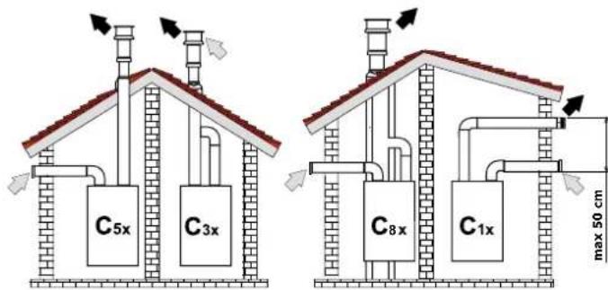
Fig. 3 - Example of a connection with separate pipes
C1x - Horizontal aspiration and evacuation on the wall. Intake and exhaust terminals must be concentric, or close enough to be exposed to similar wind conditions (maximum distance of 50 cm).
C3x - Vertical aspiration and evacuation on the ceiling. Intake/exhaust terminals suitable for C12.
C5x - Separate aspiration and evacuation on the wall or ceiling or, in any case, in areas under different pressure. Aspiration and evacuation may not be placed on opposite walls.
C6x - Aspiration and evacuation with separate certified pipes (EN 1856-2).
B3x - Aspiration from the installation environment and evacuation in the collector system.
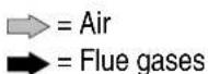
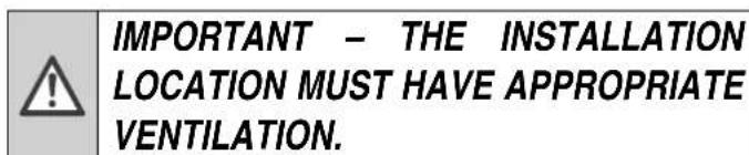
- For connecting separate pipes to ∅ 80/100 (V010039X0):
natural_image
3D rendering of a white industrial pipe fitting with two cylindrical cavities and a base plate (no text or symbols visible)Before performing the installation, make sure it does not exceed the maximum permitted length by making a simple calculation:
- Design the entire system of separate flues, including the accessories and the exhaust terminals.
- Check Table 1 and determine the losses in m_eq (equivalent meters) for each component, depending on its assembly position.
- Make sure that the total sum of the losses is less than or equal to the maximum length indicated on Table 2.
Table 1
| Loss in m_eq | |||||
| Air inlet | Flue gases outlet | ||||
| Vertical | Horizontal | ||||
| ∅ 80 | PIPE | 0.5 m M/H | 0.5 | 0.5 | 1 |
| 1 m M/H | 1 | 1 | 2 | ||
| 2 m M/H | 2 | 2 | 4 | ||
| CURVE | 45° H/H | 1.2 | 2.2 | ||
| 45° M/H | 1.2 | 2.2 | |||
| 90° H/H | 2 | 3 | |||
| 90° M/H | 1.5 | 2.5 | |||
| 90° M/H + outlet for testing | 1.5 | 2.5 | |||
| HOSE | With outlet for testing | 0.2 | 0.2 | ||
| For condensate discharge | - | 3 | |||
| T | For condensate discharge | - | 7 | ||
| TERMINAL | Wall air | 2 | - | ||
| Wall fumes with wind screen | - | 5 | |||
| FLUE | Separate for air/fumes 80/80 | - | 12 | ||
| Only exhaust vent ∅ 80 | - | 4 | |||
Table 2
| MAXIMUM PERMITTED LENGTH | |||
| CETI 10 | CETI 12 | CETI 15 | CETI 17 |
| 65 m_eq | 55 m_eq | 45 m_eq | |
3 SERVICE AND MAINTENANCE
All adjustments, start-up work and regular checks described below must be performed by an authorized technician and in compliance with applicable regulations. COINTRA does not accept any responsibility for personal injury or material damages resulting from work on the unit by people that are not authorized to do so.
3.1 ADJUSTMENTS
3.1.1 Gas conversion
COINTRA CETI water heater is only provided set for one of the following two gases:
- G20 (METHANE, NATURAL GAS)
- G30 (BUTANE, LPG)
depending on the model purchased, as indicated on the packaging and on the technical data plates.
The unit can operate with NATURAL GAS (G20, G25) or with LPG (G30, G31). The unit can be adjusted to work with a gas that is different to that set in the factory, with the following steps according to the type of gas conversion:
1 - Close the gas valve
2 - Convert via the GAS TRANSFORMATION KIT
Except for changes between G30 and G31
3 - Set the FA parameter (type of water heater and gas)
4 - Open the gas valve
5 - Calibrate the gas valve
Except for changes between G30 and G31
6 - Place the new data label
1 - Close the gas valve
Before beginning any conversion:
- The gas valve must be closed.
- The water heater must then be connected to the new gas that it is to be converted to.
2 - Convert via the GAS TRANSFORMATION KIT

The conversion for operation with a gas that is different to that set in the factory must be performed by an authorized technician, using original parts and in compliance with the applicable regulations of the country of use.

All components damaged during the conversion work must be replaced.
For every gas conversion in the CETI water heater, except in the LPG model to change between G30 and G31 (from BUTANE to PROPANE and vice versa, without a Kit), the appropriate Transformation Kit must be purchased and installed, according to the type of gas the water heater will work with, and the model in litres of the CETI that we have:
The following steps apply to install the Transformation Kit:
- Disconnect the CETI water heater from the power supply.
- Remove the burner's collector and mount the new one according to the instructions of the Transformation Kit provided.
- Connect the CETI water heater to the power supply.
3 - Set the FA parameter (type of water heater and gas)
A simple setting must be made on the electronics; simply configure the "FA" parameter correctly. This indicates the water heater's model type, that is, the litres and type of gas setting:
1 Activate the parameter list by pressing the ECO key for 5 seconds until "PP" appears on the display. Touch the Standby key and the first "FA" parameter appears.
2 To do this you must touch the Standby key and change the value of the current parameter with the “+” and “−” keys, according to the water heater model and its type of gas (see Section 3.5.1 Parameter list).
3 Once configured, confirm this initial "FA" parameter with the Standby key.
These steps always apply for the following 2 cases:
(Cases A and B)
A. Gas conversion from G30 to G31, Butane to Propane and vice versa (from G31 to G30, Propane to Butane)
If you have purchased the CETI LPG model, which will be preset at the factory to G30 (Butane), to convert it to G31 (Propane) the "FA" parameter must simply be set, which in this example would be the following setting:
Model: 10 L / 12 L / 15 L / 17 L
From factory value, G30: 3 / 3 / 8 / 13
to the new value, G31: 2 / 2 / 7 / 12
according to the litres of the water heater model, as shown in the parameter table (see Section 3.5.1). To convert the other way, always with the CETI LPG model, from G31 to G30, the process would be the same up to this point, changing the FA parameter with the corresponding value.
In this case, after changing the FA parameter no more changes must be made on the electronics, so you can continue by touching the “+” key until you reach the last “qU” parameter. From this final parameter, you must confirm and leave by touching the Standby key.
B. Gas conversion with Transformation Kit
If the gas conversion has been performed by converting the water heater, the FA parameter must also be set first, according to the gas that the CETI water heater will work with:
| Model: 10 L / 12 L / 15 L / 17 L | |
| - Transformed to G20: | 1 / 1 / 6 / 11 |
| - Transformed to GLP | (G31): 2 / 2 / 7 / 12 |
| (G30): 3 / 3 / 8 / 13 | |
| - Transformed to G25: | 4 / 4 / 9 / 14 |
and according to the litres of the water heater model, as shown in the parameter table (see Section 3.5.1).
In this case, after changing the FA parameter the gas valve must be calibrated, via consecutive parameters to FA.
4 - Open the gas valve
After confirming the new FA parameter value the water heater is already set for the new gas and the gas valve can be opened.
5 - Gas valve calibration
The gas valve must be calibrated for every gas conversion on the CETI that has been converted with the corresponding Kit (that is, for every conversion except the LPG model, which converts from G30 to G31 and vice versa).
For this follow Section 3.1.2 entirely to perform this step correctly.
6 - Placing the new gas technical data label
To show that the gas conversion has been correctly completed, place the new adhesive technical data label on the water heater's casing, replacing the one that came from the factory with the new one:
- Additional G31 gas label which comes with your CETI LPG (for conversions from G30 to G31).
- Corresponding gas label (G20, G30, G31, G25) which comes with the corresponding Transformation Kit.
3.1.2 Gas valve calibration
This must only be performed in the following cases:
- GAS VALVE REPLACEMENT
- ELECTRONIC CARD REPLACEMENT
- GAS CHANGE WITH TRANSFORMATION
The gas valve (with integrated modulating actuator) is not calibrated mechanically; the minimum and maximum capacity is adjusted electronically via 2 parameters:
| Par. | Description | Range |
| PH | Total Maximum Pressure (entire burner) | 20 - F0 |
| P2 | Minimum Pressure (burner minimum section) | 20 - F0 |
1 Check that the supply pressure according to the type of gas complies with that shown on the Technical Data Table (see Section 4.3).
2 On the same Technical Data Table, check the Maximum Pressure and Minimum Pressure values of your water heater, according to the water heater model and type of gas, to take them into account in the following steps.
3 Connect a gauge to check the outlet pressure of the gas valve.
4 Activate the parameter list by pressing the ECO key for 5 seconds until "PP" appears on the display. Touch the Standby key and the first "FA" parameter appears.
5 ELECTRONIC CARD REPLACEMENT. If we are changing the card, this first "FA" parameter, which indicates the type of the burner model, must first also be configured correctly.
6 To do this you must touch the Standby key and change the value of the current parameter with the "+" and "-" keys, according to the water heater model and its type of gas (see Section 3.5.1 Parameter list). Once configured, confirm this initial "FA" parameter with the Standby key.
7 NOTE: In the CETI 10 model, when confirming "FA" after replacing the electronic card, the value of parameter "FH" must be manually configured with the corresponding one in the table in Section 3.5.1 List of Parameters.
8 Touch the “+” key once and the first parameter of the valve to be calibrated appears, “PH”, relative to Maximum Pressure.
9 Selecting "PH", you must touch the Standby key to enter its calibration, showing its internal value of the Maximum Pressure parameter.
10 To set the "PH" parameter, touch the "+" or "-" key on the panel until the gauge shows the Maximum nominal Pressure minus 1 mbar. Wait 10 seconds for the pressure to stabilize. If the gauge shows a different value to the maximum nominal pressure, increase the "PH" parameter in steps with the "+" key. After each change, wait 10 seconds for the pressure to stabilize. If the gauge shows the same value as the Maximum nominal Pressure, confirm it with the Standby key.
11 To set the next parameter to be calibrated, from "PH" you must touch the "+" key 8 times, until you reach the "P2" parameter, relative to the Minimum Pressure.
12 Selecting "P2", you must touch the Standby key to enter its calibration, showing its internal value of the Minimum Pressure parameter.
13 To adjust the "P2" parameter, touch the "+" or "-" key on the panel until the gauge shows the Minimum nominal Pressure plus 0.5 mbar. Wait 10 seconds for the pressure to stabilize. If the gauge shows a different value to the minimum nominal pressure, reduce the "P2" parameter in steps with the "-" key. After each change, wait 10 seconds for the pressure to stabilize. If the gauge shows the same value as the Minimum nominal Pressure, confirm it with the Standby key.
14 To complete the calibration process you must then touch the “+” key until you reach the final “qU” parameter. From this final parameter, you must confirm and exit by touching the Standby key.
15 Disconnect the gauge.
3.2 COMMISSIONING

Commissioning of the water heater must be performed by a trained, specialized technician.
Checks that must be performed during the first ignition, after maintenance work which requires the unit to be disconnected and after every intervention on the unit's safety devices or components.
3.2.1 Before turning the water heater on
- Check the tightness of the gas installation carefully for leaks on the connections using a soap and water solution.
- Fill the hydraulic installation and check that there is no air in either the unit or the installation.
- Check that there are no water leaks in the installation or the unit.
- Check that the connection to the electrical system and the grounding are correct.
- Check that the gas pressure is correct.
- Check that there are no flammable liquids or materials near the water heater.
- Do not place the water heater on the floor with the connections facing down, so the connections are not damaged.
3.2.2 Checks during operation
- Turn the unit on.
- Make sure the fuel and water systems are tight.
- Check the efficiency of the air and flue gas ducts while the water heater is operating.
- Check that the gas valve modulates correctly.
- Check that the water heater ignites easily by doing a few on and off tests.
- Check that the fuel consumption indicated on the meter matches that shown in the Technical Data Table, Section 4.3.
3.3 MAINTENANCE
3.3.1 Regular check
In order for the unit to operate correctly, an authorized technician must perform an annual inspection, checking that:
- The control and safety devices (gas valve, flow switch, etc.) work correctly.
• The exhaust vent is perfectly efficient. - The air and flue gas ducts and terminal are free of obstacles and leaks.
- The burner and the exchanger have no dirt or deposits. Do not use chemicals or steel brushes to clean them.
- The electrode is free of deposits and properly positioned.
- The gas and water systems are perfectly tight.
- The gas delivery and operating pressure values are as indicated on the tables.

A soft, damp cloth may be used to clean the casing and exterior parts of the water heater, using soapy water if necessary. Do not use abrasive detergents or solvents.
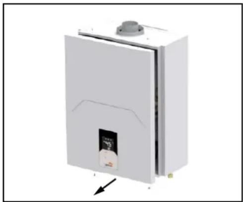
3.3.2 Opening the casing
To open the casing:
1 Unscrew the screws
2 Remove the front panel
3 Disconnect the Display Panel's wiring

Before doing any work inside the water heater, disconnect the power supply and close the gas valve.
natural_image
3D rendering of a white industrial cabinet with a lid and label, showing internal structure and an arrow pointing to the bottom section (no text or symbols on the cabinet itself)3.4 ERRORS
The water heater is fitted with an advanced self-testing system. If a problem arises with the unit, the fault symbol will flash on the display and the respective code will be displayed, with an acoustic signal sounding at the same time. If a fault occurs, all gas valves close immediately. The fan continues moving for 30 seconds, until it stops. With the E2 error, the fan will continue moving until the flame signal disappears, at which point it will stop 30 seconds later.
To reset the unit's operation after an error, it is enough to just close the hot water tap, or to touch the Standby key, to put the water heater into STANDBY. With the E2 error, the user must unplug the water heater and plug it in again to reset it. If the error persists after these reset steps, the fault must be resolved.
3.4.1 Error list
| Code Error Possible cause | ||
| E0 Outlet probe fault Water outlet NTC temperature probe sensor open or shorted | ||
| E1 Misfire or no flame | The system does not detect a flame after two attempts to ignite, or there is no flame during normal operation | |
| E2 There is a flame fault | Before starting the system detects the flame, or after the system stops for 5 s and then detects the flame | |
| E3 | Overheating cut-off thermostat | Overheating safety cut-off thermostat circuit open |
| E4 Inlet probe fault Water inlet NTC temperature probe sensor open or shorted | ||
| E5 | Fan fault | Speed continuously under 600r/min for 2 s, or the system cannot detect the speed signal |
| E6 ACS overheating Water outlet NTC probe sensor temperature above 85 °C for 5 s | ||
| E7 Valve fault Valves that activate shorted transistors or valves in open circuit | ||
| E8 Blocked pipe | Fan speed above the wind screen pressure warning speed preset by the software, or above the HC or LC values shown in the parameter menu (see HC and LC parameters) | |
| En | ACS time up | Maximum continuous heating time, according to nE (60 min by default, see nE parameter) |
| EC / Ec | Display panel connection | Fault on the main electronic card's communication wiring with the display panel |
3.4.2 Error History
From the STANDBY state, keep the “-” key pressed for 5 seconds to access the Error History Interface, initially showing “HI”. Touching the Standby key you begin to see the last 10 Errors that occurred in the water heater. At this point the lower display shows the last error code that occurred, and the upper display shows “01”, beginning to list the errors that occurred. Scrolling through them, 01\~10, the last ten water heater error codes appear. Touch the Standby key to exit the history view.
Touch the “-” key to change from “HI” to recovery of Errors “rE”; from this option, keep the ECO key pressed for 5 seconds to delete the history (the 10 Errors) and exit the interface at the same time. From either of the two modes, “HI” or “rE”, keep the “-” key pressed for 5 seconds to exit the error history interface.
3.5 PARAMETERS
There is a parameter list (which the user cannot change), to make internal settings in the water heater. Access to the Parameter menu is made from the STANDBY state keeping the ECO key pressed for 5 seconds, until "PP" appears on the display. Touch the Standby key and the first "FA" parameter appears on the display.
All parameters can be changed from the control panel. The “+” key or the “−” key are used to scroll through the parameter list, to reach the parameter you want to set. Once you have selected the parameter you want, touch the Standby key and you will see its current value. To change the parameter's value touch the “+” or “−” keys until you reach the value you want.
To confirm the value touch the Standby key, returning to show the parameter list, to go forward or back to a different parameter to set it. After setting the parameters you want, you must reach the last parameter of the "qU" list (touching the "+" key until you get to it), and confirm the completed configuration by touching the Standby key from this parameter, to exit saving all changes.
3.5.1 Parameter list
| P. | Description Range Default value | |||||||||||||||||||||||||
| FA | Unit regulation:- Litres (10 L, 12 L, 15 L, 17 L)- Gas type (G20, G31, G30, G25, G230) | 1 - 15 | CETI 10 CETI 12 CETI 15 CETI 17 | |||||||||||||||||||||||
| G20 | G31 G | 30 G25 | G230 | G20 | G31 G | 30 G25 | G230 | G20 | G31 G | 30 G25 | G230 | G20 | G31 G | 30 G25 | G230 | G20 | G31 G | 30 G25 | ||||||||
| 1 2 | 3 4 5 | 1 2 3 4 | 5 6 7 | 8 9 10 | 11 12 | 13 14 | 15 | |||||||||||||||||||
| PH | MAXIMUM Pressure – Entire burner | 20 - F0 9d b7 | A5 b3 | A8 b7 | dE C | 1 C6 | b7 9A | bC A6 | A9 9d | A9 d | 3 b2 | bC AC | ||||||||||||||
| FH | Maximum fan speed – Entire burner | 20 - F0 95 A1 | A2 7c | 91 A4 | A3 A3 | A4 A3 | bb A | d b4 | A5 bb | Cd d1 | Cd Cd | Cd | ||||||||||||||
| PL | Minimum pressure – Entire burner | 20 - F0 6c 6F | 6F 6c | 6F 6c | 6F 6F | 6c 6F | 71 7d | 75 7B | 74 71 | 7d 7$ | 7B 74 | |||||||||||||||
| FL | Minimum fan speed – Entire burner | 20 - F0 4E 4d | 4d 4E | 4d 4E | 4d 4d | 4E 4d | 67 64 | 62 67 | 67 67 | 64 62 | 67 67 | |||||||||||||||
| dH | Start-up pressure | 20 - F0 63 8F | 8F 83 | 8F 83 | 8F 8F | 83 8F | 80 A0 | A0 84 | 83 80 | A0 A0 | 84 83 | |||||||||||||||
| dF | Fan speed during Start-up | 20 - F0 5F 4d | 4d 5F | 4d 5F | 4d 4d | 5F 4d | 6A 60 | 75 6A | 6A 6A | 6A 60 | 75 6A | 6A | ||||||||||||||
| P1 | Maximum pressure – Burner minimum section | 20 - F0 C1 dA | dA C1 | dA C1 | dA dA | A C1 | dA A8 | f0 d6 | b7 Ab | A8 F0 | d6 b7 | Ab | ||||||||||||||
| F1 | Maximum fan speed – Burner minimum section | 20 - F0 9b 98 | 98 9b | 98 9b | 98 9b | 9b 9b | dA C3 | C8 dA | dA c3 | C8 dA | dA dA | |||||||||||||||
| P2 | MINIMUM Pressure – Burner minimum section | 20 - F0 6d 75 | 71 6E | 6E 6d | 75 71 | 6E 6E | 6E 83 | 7b 72 | 71 6E | 83 7b | 72 72 | 71 | ||||||||||||||
| F2 | Minimum fan speed – Burner minimum section | 20 - F0 53 4A | 4A 53 | 4A 53 | 4A 4A | 53 4A | 6d 77 | 76 6d | 6d 6d | 6d 77 | 76 6d | 6d | ||||||||||||||
| P3 | Maximum pressure – Burner section 2 | 20 - F0 | E A3 | Ad bE | bE bE | A3 A | d bE bE | 97 bF | b1 A0 | 9A | 97 bF | b1 A0 | 9A | |||||||||||||
| F3 | Maximum fan speed – Burner section 2 | 20 - F0 b | A5 d3 | b6 b3 | A8 A5 | d3 b6 | b3 A8 | |||||||||||||||||||
| P4 | Minimum pressure – Burner section 2 | 20 - F0 | 66 70 | 6d 68 | 69 66 | 70 6d | 68 69 | |||||||||||||||||||
| F4 | Minimum fan speed – Burner section 2 | 20 - F0 | 45 4E | 4E 45 | 45 4E | 4E 45 | 45 | |||||||||||||||||||
| P5 | Maximum pressure – Burner section 3 | 20 - F0 A5 | C8 | C8 C9 | C9 C9 | C8 C9 | C9 | |||||||||||||||||||
| F5 | Maximum fan speed – Burner section 3 | 20 - F0 | ||||||||||||||||||||||||
| P6 | Minimum pressure – Burner section 3 | 20 - F0 | 71 80 | 77 75 | 74 71 | 80 77 | 75 74 | |||||||||||||||||||
| F6 | Minimum fan speed – Burner section 3 | 20 - F0 | 64 69 | 69 64 | 64 64 | 69 69 | 64 64 | |||||||||||||||||||
| HC | Fan safety cut-off speed at Maximum Pressure | 20 - 89 | 67 Hz | 67 Hz | 82 Hz | 82 Hz | ||||||||||||||||||||
| LC | Fan safety cut-off speed at Minimum Pressure | 20 - 89 | 34 Hz | 34 Hz | 56 Hz | 56 Hz | ||||||||||||||||||||
| nE | Burner continuous operation timing | OFF /20 - 60 | 60 min | |||||||||||||||||||||||
| nP | Enable or Disable Operational State memory | OFF - ON | ON | |||||||||||||||||||||||
| FC | Enable or Disable Solar Energy Function | OFF - ON | OFF | |||||||||||||||||||||||
| S1 | Solar function – ON hysteresis | 1 - 20 | 10 °C | |||||||||||||||||||||||
| S2 | Solar function – OFF hysteresis | 1 - 20 | 10 °C | |||||||||||||||||||||||
| t1 | Solar function – Initial time to turn the burner on | 0 - 20 | 10 s | |||||||||||||||||||||||
| nS | Maximum hot water temperature Setting | 50 - 65 | 50 °C | |||||||||||||||||||||||
| nL | Caudal de agua mínimo para Inicio/Parada- 0: 4/3.5 L/min - 1: 3.5/3 L/min - 2: 3/2.5 L/min- 3: 2.5/2 L/min - 4: 2/1.5 L/min | 0 - 4 | 2 (3/2.5 L/min) | |||||||||||||||||||||||
| qU | EXIT and SAVE changes | - | - | |||||||||||||||||||||||
Notes:
The parameters that show different values, vary the operating mode (never the range) in relation to the initial FA parameter (water heater model according to the type of Gas and Litres). The parameters marked in gray (from P3 to F6) only appear in the real parameter list if the FA value is between 6 and 15 (that is, for the 15 Litres and 17 Litres models).
4 CHARACTERISTICS AND TECHNICAL DATA
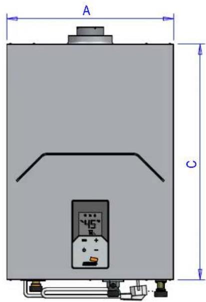
4.1 Dimensions and connections
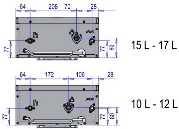
15 L - 17 L
10 L - 12 L
natural_image
Technical diagram of a cylindrical mechanical component with mounting base and side profile (no text or symbols)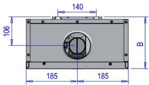
| Model | A(mm) | B(mm) | C(mm) | Connections | ||
| Cold Water | Hot Water | Gas | ||||
| CETI 10 | 370 | 190 | 525 1/2” | |||
| CETI 12 | ||||||
| CETI 15 | ||||||
| CETI 17 | ||||||
4.2 Overview and main components
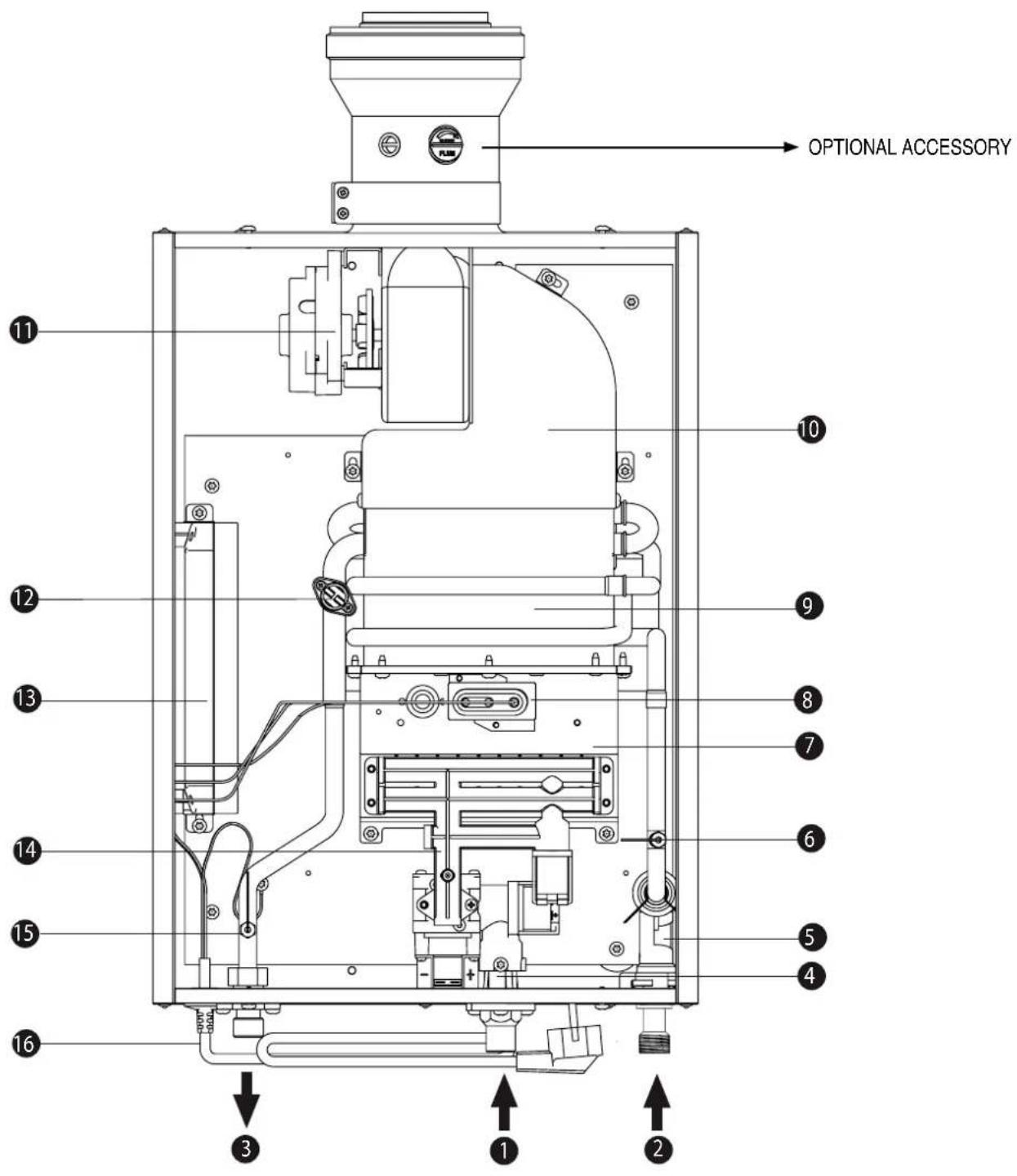
[1] Gas inlet
[2] Cold water inlet
[3] Domestic hot water outlet (ACS)
[4] Gas valve
[5] Water flow sensor
[6] Cold water temperature sensor
[7] Burner assembly
[8] Electrode assembly
[9] Copper exchanger
[10] Combustion chamber
[11] Fan
[12] Temperature limiter
[13] Control panel
[14] Gas distributor
[15] Hot water temperature sensor
[16] Connection hose
4.3 Technical Data Table
In the LPG units supplied with only one bottle, installation with Propane (G31) is recommended for better gasification.
| Data Unit CETI 10 CETI 12 CETI 15 CETI 17 Notes | |||||||
| CODE - | V0DK93IAM V0DK96IAM V0DK95IAM V0DK97IAM G20 | ||||||
| V0DK93KAM V0DK96KAM V0DK95KAM V0DK97KAM G30 | |||||||
| - Unit categories- Destination countries:ES - PT- FR | - | II_2R3R (ES, PT, FR) II_2H3P (PT) II_2Es3P (FR) II_2E3P (FR) | |||||
| Maximum heat capacity (Hi) kW 19.7 23 29.7 | 33 Q (Hi) | ||||||
| Minimum heat capacity (Hi) | kW | 4 | 4 | 4 | 4 | Q (Hi) | |
| Maximum heat capacity | kW | 18.4 | 20.9 | 27 | 30 | P | |
| Minimum heat capacity | kW | 3.6 | 3.6 | 3.6 | 3.6 | P | |
| Burner injectors G20 | N.° x ∅ | 10 x 0.7410 x 1.07 | 10 x 0.7410 x 1.07 | 16 x 0.7516 x 1.13 | 16 x 0.7516 x 1.13 | ||
| G20 | Supply pressure G20 | mbar | 20 | ||||
| Maximum Pressure burner G20 | mbar | 9.5 | 12.5 | 7.3 | 9 | ||
| Minimum Pressure burner G20 | mbar | 2.5 | 2.5 | 3 | 3 | ||
| G20 flow rate – Max / min | m3/h | 2.08 / 0.42 | 2.43 / 0.42 | 3.14 / 0.42 | 3.49 / 0.42 | ||
| CO2– G20 – Max / min | % | 5.1 / 1.9 | 5.7 / 1.9 | 4.4 / 1 | 4.8 / 1 | ||
| Burner injectors G25 | N.° x ∅ | 10 x 0.8010 x 1.15 | 10 x 0.8010 x 1.15 | 16 x 0.8516 x 1.20 | 16 x 0.8516 x 1.20 | ||
| G25 | Supply pressure G25 | mbar | 25 | ||||
| Maximum Pressure burner G25 | mbar | 12.7 | 14.5 | 8.7 | 10.5 | ||
| Minimum Pressure burner G25 | mbar | 3 | 3 | 3.6 | 3.6 | ||
| G25 flow rate – Max / min | m3/h | 2.45 / 0.49 | 2.83 / 0.49 | 3.66 / 0.49 | 4.06 / 0.49 | ||
| CO2– G25 – Max / min | % | 5.1 / 1.9 | 5.7 / 1.9 | 4.4 / 1 | 4.8 / 1 | ||
| Burner injectors G30 / G31 | N.° x ∅ | 10 x 0.5010 x 0.75 | 10 x 0.5010 x 0.75 | 16 x 0.4716 x 0.75 | 16 x 0.4716 x 0.75 | ||
| G30 | Supply pressure G30 | mbar | 29 | ||||
| Maximum Pressure burner G30 | mbar | 11.7 | 15.5 | 10.8 | 12.8 | ||
| Minimum Pressure burner G30 | mbar | 3.8 | 3.8 | 5.7 | 5.7 | ||
| G30 flow rate – Max / min | kg/h | 1.55 / 0.32 | 1.81 / 0.32 | 2.34 / 0.32 | 2.6 / 0.32 | ||
| CO2– G30 – max/min | % | 5.8 / 1.9 | 6.5 / 1.9 | 5 / 1.2 | 5.4 / 1.2 | ||
| G31 | Supply pressure G31 | mbar | 37 | ||||
| Maximum Pressure burner G31 | mbar | 14.4 | 20.5 | 14.5 | 18 | ||
| Minimum Pressure burner G31 | mbar | 4.3 | 4.3 | 7.5 | 7.5 | ||
| G31 flow rate – Max / min | kg/h | 1.53 / 0.31 | 1.79 / 0.31 | 2.31 / 0.31 | 2.56 / 0.31 | ||
| CO2– G31 – Max / min | % | 5.8 / 1.9 | 6.5 / 1.9 | 5 / 1.2 | 5.4 / 1.2 | ||
| NOx emission class | - | 6 (< 56 mg/kWh) | NOx | ||||
| Max. operating pressure | bar | 10 | pw | ||||
| Min. operating pressure | bar | 0.2 | |||||
| ACSflow rate | Δ 25° Max | l/min | 10 | 12 | 15.5 | 17 | |
| Δ 30° Max | l/min | 8 | 10 | 12.9 | 14.3 | D | |
| Maximum operating temperature(configurable via parameter) | °C | 65 | tmax | ||||
| Protection rating | IP | IPX4D | |||||
| Supply voltage | V - Hz | 230 V - 50 Hz | |||||
| Absorbed electrical power | W | 33 | 34 | 36 | 48 | ||
| Empty weight | kg | 13.7 | 13.7 | 14.5 | 14.5 | ||
| Types of unit | - | B32-C12-C22-C32-C42-C52-C62-C82-C92 | |||||
| CE | - | 0085 / 22 | |||||
| Maximum flue pressure at Pmax | Pa | 80 | |||||
| Brand: COINTRA | ||||||
| Type of product: Sealed water water heater | ||||||
| MODEL CETI 10 CETI 12 CETI 15 CETI 17 | ||||||
| CETI M – METHANE | CODE | V0DK93IAM V0DK96IAM V0DK95IAM V0DK97IAM | ||||
| CETI LPG – LIQUEFIED PETROLEUM GAS | V0DK93KAM V0DK96KAM V0DK95KAM V0DK97KAM | |||||
| Element Symbol Unit Value | ||||||
| Declared load profile -- M XL XL XL | ||||||
| Energy efficiency class for water heating (A+ a F) -- A A A A | ||||||
| Daily electricity consumption | Qelec | kWh | 0.082 | 0.082 | 0.082 | 0.082 |
| Annual electricity consumption | AEC | kWh | 18 | 18 | 18 | 18 |
| Water heating energy efficiency | NWh | % | 85 | 85 | 85 | 85 |
| Daily fuel consumption | Qfuel | kWh | 21.052 | 21.052 | 20.996 | 20.996 |
| Annual fuel consumption | AFC | GJ | 18 | 18 | 18 | 18 |
| Thermostat temperature settings, as placed on the market | - | - | MAX | |||
| Sound power level, indoors | LWA | dB | 54 | 54 | 56 | 56 |
| Nitrogen oxide emissions | NOx | mg/kWh | 32 | 32 | 26 | 26 |
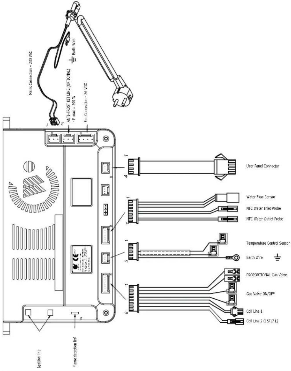
4.4 Electrical diagram
Warranty Certificate
This warranty is only valid for equipment to be marketed, sold and installed in Spanish territory.
GUARANTOR: FERROLI ESPAÑA, S.L., with registered office at Pol. Ind. Villayuda, C/ Alcalde Martín Cobos, 4, 09007 Burgos, guarantees the products listed in this instruction manual in accordance with the modification of 1 January 2022 of Royal Legislative Decree 1/2007 of 16 November, which approves the revised text of the General Law for the Defence of Consumers and Users and other complementary laws.
The 3-year warranty period indicated in the aforementioned Royal Decree shall start from the date of installation or, failing that, from the date of purchase.
Unless proven otherwise, it shall be presumed that any lack of conformity that is shown 2 years after delivery was not apparent when the good was delivered.
Scope of warranty
The warranty does not cover incidents caused by:
- Power supply with generator sets or any other system that is not a stable electrical network.
- Transport not carried out at the company's expense (to be claimed directly from the carrier).
- Handling of the product by personnel unconnected to the guarantor during the warranty period.
- If mounting does not comply with the instructions supplied with the machine.
- Installation of the machine does not comply with the Laws and Regulations in force (electricity, hydraulics, fuels, etc.).
- Faulty hydraulic or electrical installation, faults in fuel supply systems, combustion exhaust outlets, chimneys or drainage systems.
- Faults due to incorrect feed water treatment, due to limescale deposits, due to incorrectly carried out descaling treatment, etc.
- Faults caused by condensation or atmospheric conditions (ice, lightning, floods, etc.), as well as erratic currents.
- Inadequate maintenance, neglect or misuse.
• Corrosions caused by inadequate storage.
Important
- To be entitled to the warranty claim stated herein, it will be an essential requirement that the equipment is intended for domestic use.
- This warranty is valid provided that the standard maintenance operations described in the technical instructions supplied with the equipment are carried out.
- Prior to any technical assistance, the guarantor's technical staff must be shown the invoice or purchase receipt of the equipment, together with the corresponding delivery note, if this were of a later date.
- The spare parts which are necessary to replace, will be those determined by our Official T.A.S., and in all cases they will be originals from the guarantor.
The material replaced under warranty shall become the property of the guarantor.
Any complaints shall be lodged with the competent body in this matter.
Technical Assistant Service
Tel: 912 176 834 - serviciotecnico@cointra.es

COINTRA


- CE
- FUNCIONAMIENTO
- ERRORES
- FUNCIONAMENTO
- ERROS
- FONCTIONNEMENT
- ERREURS
- INDEX
- INSTRUCTIONS FOR USE....61
- INSTALLATION INSTRUCTIONS....63
- SERVICE AND MAINTENANCE....67
- CHARACTERISTICS AND TECHNICAL DATA 72
- INSTRUCTIONS FOR USE
- Presentation
- OPERATION
- ON and OFF
- NORMAL Operation
- Temperature Setting
- Domestic Hot Water
- ECO mode
- Enabling ECO mode
- Temperature Setting in ECO mode
- Disabling ECO mode
- Solar Energy Function
- INSTALLATION INSTRUCTIONS
- General instructions
- Installation location
- Installing the water heater
- Hydraulic connections
- Gas connection
- Electrical connections
- Air and flue gas ducts
- Connection with coaxial pipes
- Connection with separate pipes
- SERVICE AND MAINTENANCE
- ADJUSTMENTS
- Gas conversion
- - Close the gas valve
- - Convert via the GAS TRANSFORMATION KIT
- - Set the FA parameter (type of water heater and gas)
- Gas conversion with Transformation Kit
- - Open the gas valve
- - Gas valve calibration
- - Placing the new gas technical data label
- Gas valve calibration
- This must only be performed in the following cases:
- COMMISSIONING
- Before turning the water heater on
- Checks during operation
- MAINTENANCE
- Regular check
- Opening the casing
- To open the casing:
- ERRORS
- Error list
- Error History
- PARAMETERS
- Notes:
- CHARACTERISTICS AND TECHNICAL DATA
- Overview and main components
- Technical Data Table
- Warranty Certificate
- This warranty is only valid for equipment to be marketed, sold and installed in Spanish territory.
- Scope of warranty
- The warranty does not cover incidents caused by:
- Important
- COINTRA
Brand : COINTRA
Model : CETI 15-N
Category : Boiler