K-8298 - Toilet KOHLER - Free user manual and instructions
Find the device manual for free K-8298 KOHLER in PDF.


User questions about K-8298 KOHLER
0 question about this device. Answer the ones you know or ask your own.
Ask a new question about this device
Download the instructions for your Toilet in PDF format for free! Find your manual K-8298 - KOHLER and take your electronic device back in hand. On this page are published all the documents necessary for the use of your device. K-8298 by KOHLER.
USER MANUAL K-8298 KOHLER
natural_image
Line drawing of a computer toilet with buttons and lid (no text or symbols)Français, page "Français-1" Español, pagina "Español-1"
THE BOLD LOOK OF KOHLER®
1233549-2-B
Before You Begin

WARNING: Riskofelectricshock, fire, or personal injury. This product must be grounded and connected only to a dedicated, nominal 120 VAC, 60 Hz circuit protected by a minimum 15 A Ground-Fault Circuit-Interrupter (GFCI) or Residual Current Device (RCD).

WARNING: Riskofelectricshock. Do not immerse or flush the product with water.
IMPORTANT!Riskofproductdamage.Do not install this product in a location exposed to excessive moisture where condensation might form on the product surface.
IMPORTANT!Riskofproductorpropertydamage.Pushing or pulling on the water connection may cause water leakage.
IMPORTANT!Riskofproductdamage.Do not supply electrical power to the unit until the plumbing installation work has been completed; it could cause the product to malfunction.
NOTE: The thermal protectors may trip during storage or transportation in warm weather causing the unit to not operate. Allow the unit to cool to room temperature before installation or operation.
□ Observe all local plumbing, electrical, and building codes.
☐ Only connect the seat to a cold water supply of drinking quality at a pressure of 20 (139 kPa) - 80 psi (551 kPa).
Tools and Materials

natural_image
Line drawings of four different tools: an adjustable wrench, screwdriver, screwdriver with screw, and rolled-up sheet (no text or symbols)Plastic Wrap
text_image
Grounded Outlet Grounding Plug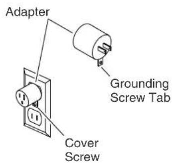
text_image
Adapter Grounding Screw Tab Cover ScrewTemporary ConnectionPreferred Connection
Grounding Instructions
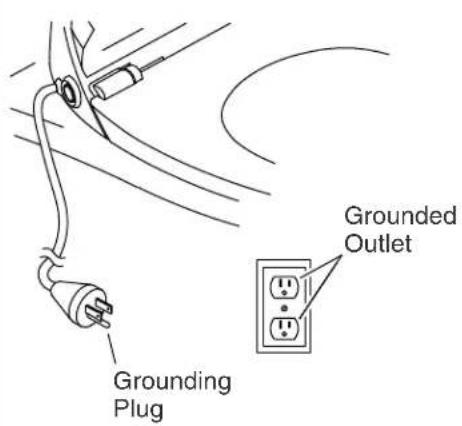
☐ This product should be grounded. In the event of an electrical short circuit, grounding reduces the risk of electric shock by providing an escape wire for the electric current. This product is equipped with a cord having a grounding wire with a grounding plug. The plug must be plugged into an outlet that is properly installed and grounded.

DANGER: Riskofelectricshock. Improper use of the grounding plug can result in a risk of electric shock.
☐ If repair or replacement of the cord or plug is necessary, do not connect the grounding wire to either flat blade terminal. The wire with insulation having an outer surface that is green with or without yellow stripes is the grounding wire.
☐ Check with a qualified electrician or service personnel if the grounding instructions are not completely understood, or if in doubt as to whether the product is properly grounded.
NOTICE: Follow local codes when determining the connection type. The temporary connection may not be permitted by local electrical codes.
NOTICE: To avoid possible product malfunction, do not plug in the seat until instructed.
Preferred Connection
□ Connect the grounding plug into a grounded outlet that has the same configuration as the plug.
Grounding Instructions (cont.)
Temporary Connection
NOTICE: Unless the outlet cover screw is grounded through the house wiring, attaching the adapter grounding screw tab to the cover screw will NOT ground the unit. If there is any doubt whether the cover screw is grounded, have it checked by a qualified electrician or service professional.
☐ A temporary connection with a two-prong adapter may be used where local codes permit, provided the adapter is grounded.
text_image
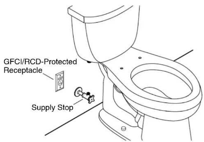
GFCI/RCD-Protected Receptacle Supply Stop1. Install an Electrical Outlet

WARNING: Riskofelectricshock, fire, or personal injury.
This product must be grounded and connected only to a dedicated, nominal 120 VAC, 60 Hz circuit protected by a minimum 15 Amp Ground-Fault Circuit-Interrupter (GFCI) or Residual Current Device (RCD).
NOTICE: Do not use an extension cord with the product.
NOTE: Follow local codes when determining the electrical outlet location.
☐ Install a 120 V GFCI- or RCD-protected electrical outlet within 32" (813 mm) of the toilet to accommodate the length of the power cord.
☐ Do not plug in the seat until instructed to do so.
text_image
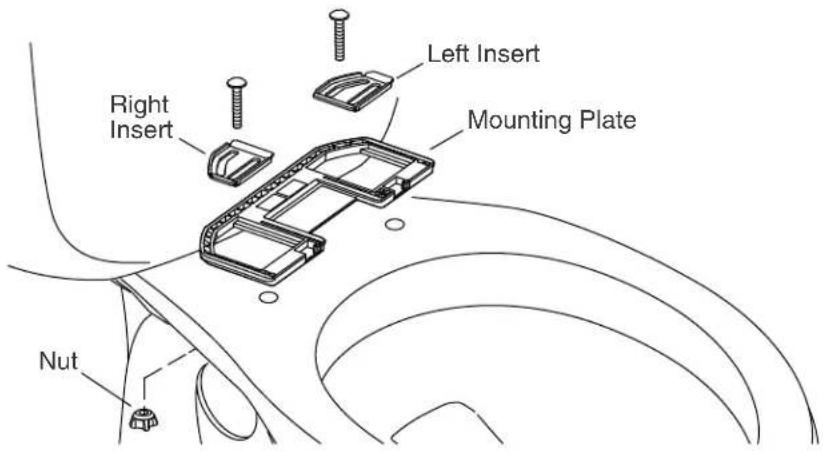
Left Insert Right Insert Mounting Plate Nut2. Install the Mounting Plate
☐ Position the mounting plate over the mounting holes on the bowl.
☐ Position the left and right inserts in the grooves on the mounting plate
☐ Fortoiletswiththreadedmountingholes: Insert the bolts through the inserts and thread into the mounting holes. Do not fully tighten at this time.
☐ Forallotherinstallations: Insert the bolts through the inserts and into the mounting holes. Thread a nut onto each bolt. Do not fully tighten at this time.
text_image
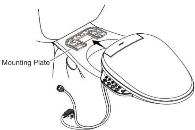
Mounting Plate3. Install the Seat
Position the Seat
☐ Slide the seat onto the mounting plate until you feel it snap into place.
□ Check the positioning of the seat. Adjust the position if needed.
Adjust the Seat
☐ To adjust the seat position, remove the seat by pressing in the release button and sliding the seat forward.
□ Reposition the mounting plate as needed.
Install the Seat
□ Securely tighten the mounting plate bolts and nuts.
☐ Slide the seat onto the mounting plate until you feel it snap into place.
text_image
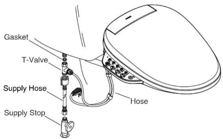
Gasket T-Valve Supply Hose Supply Stop Hose4. Connect the Water Supply

CAUTION: Riskofpropertydamage. Do not push or pull on the water connection between the seat and the water supply stop. This will prevent water leakage.
NOTICE: Use care to avoid cross threading or overtightening the connections. Use an adjustable wrench to tighten one-quarter turn past hand-tight.
□ Connect the T-valve to the seat hose.
☐ If needed, connect the supply hose to the supply stop.
□ Connect the supply hose to the T-valve.
□ Connect the T-valve to the water inlet on the toilet tank.
□ Turn on the water supply.
□ Check all connections for leaks and make any adjustments as needed.

text_image
Plastic Wrap5. Installation Checkout
NOTE: Covering the seat with plastic wrap is optional. The features can be tested while sitting on the cleansing seat or covering the wand with your hand.
NOTE: When testing the features, apply pressure to the right side (facing the toilet) of the seat. The features will not activate if there is no pressure on the seat.
□ Wrap the seat with plastic wrap. This will prevent water from spraying beyond the toilet during testing.
☐ Plug the power cord into the electrical outlet. The seat will go through a power-up sequence. The seat will go silent when the power-up is complete.
□ Refer to the Homeowners Guide to test the various seat features.