310260 - Fan Kichler - Free user manual and instructions
Find the device manual for free 310260 Kichler in PDF.

User questions about 310260 Kichler
0 question about this device. Answer the ones you know or ask your own.
Ask a new question about this device
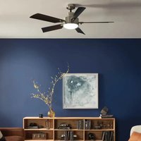
Download the instructions for your Fan in PDF format for free! Find your manual 310260 - Kichler and take your electronic device back in hand. On this page are published all the documents necessary for the use of your device. 310260 by Kichler.
USER MANUAL 310260 Kichler
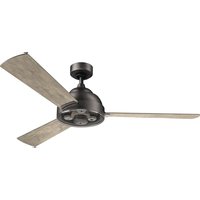
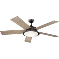
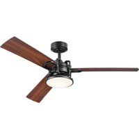
Product images may vary slightly from actual product.
natural_image
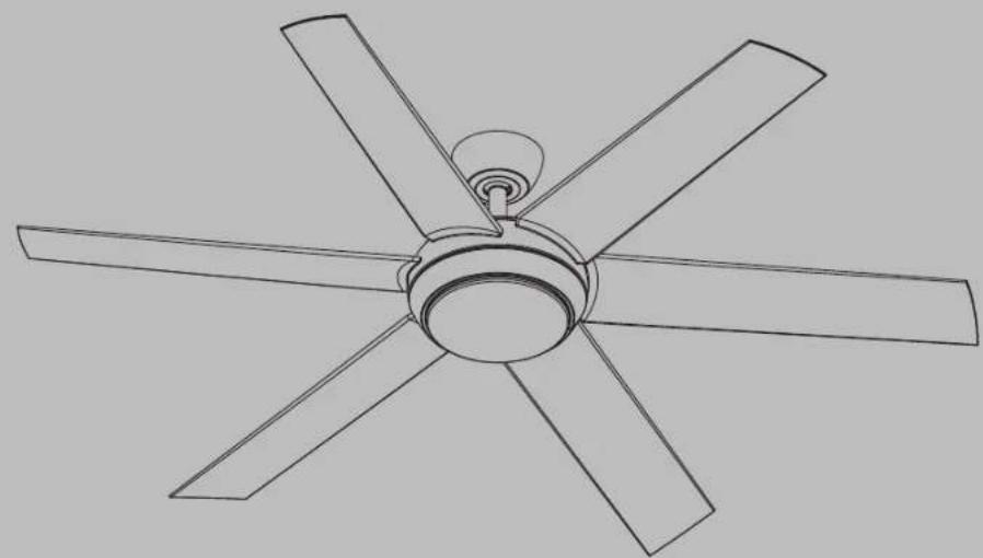
Line drawing of a five-blade ceiling fan with no text or symbolsINSTRUCTION MANUAL
Model# 310260READ
2 | KICHLER.COM
TABLE OF CONTENTS
SAFETY RULES 4
TOOLS AND MATERIALS REQUIRED....7
PACKAGE CONTENTS ....7
MOUNTING OPTIONS....8
HANGING THE FAN 9
INSTALLATION OF SAFETY CABLE....12
ELECTRICAL CONNECTIONS....12
FINISHING THE MOTOR INSTALLATION ....15
ATTACHING THE FAN BLADES....16
INSTALLING THE MOUNTING PLATE....16
SELECTING LED COLOR TEMPERATURE AND INSTALLING THE LIGHT KIT AND DIFFUSER....17
INSTALLING THE COOLTOUCH WALL PLATE ....18
INSTALLING THE TRANSMITTER....18
OPERATING INSTRUCTIONS....19
TROUBLESHOOTING....23
FCC INFORMATION 25
SAFETY RULES
READ AND SAVE THESE INSTRUCTIONS
WARNING: FOR CANADA, THIS FAN MUST BE SECURED DIRECTLY TO THE BUILDING STRUCTURE / CEILING JOIST. DON'T SECURE THIS FAN TO AN OUTLET BOX.
- CAUTION – RISK OF SHOCK: Disconnect Power at the main circuit breaker panel or main fusebox before starting and during the installation.
- WARNING: All wiring must be in accordance with the National Electrical Code "ANSI/NFPA 70" and local electrical codes. Electrical installation should be performed by a qualified licensed electrician.
- WARNING: To reduce the risk of electric shock, this fan must be installed with a general-use, isolating wall control/switch.
- WARNING: Not suitable for use with solid-state speed controls.
- WARNING: To reduce the risk of fire, electric shock, or personal injury, mount to outlet box marked "acceptable for fan support of 15.9 kg (35 lbs.) or less" and use mounting screws provided with the outlet box. Most outlet boxes commonly used for the support of light fixtures are not acceptable for
fan support and may need to be replaced. Due to the complexity of the installation of this fan, a qualified licensed electrician is strongly recommended.
-
The outlet box and support structure must be securely mounted and capable of reliably supporting a minimum of 15.9 kg (35 pounds). Use only cULus Listed outlet boxes marked "Acceptable for Fan Support of 15.9 kg (35 lbs) or less".
-
The fan must be mounted with a minimum of 2.1 m (7 feet) clearance from the trailing edge of the blades to the floor.
-
To operate the reverse function on this fan, press the "Reverse" Button on the transmitter while fan is running.
-
Avoid placing objects in the path of the blades.
-
WARNING: make sure the power is disconnected before cleaning your fan.
SAFETY RULES (continued)
other items, be cautious when working around or cleaning the fan.
- Do not use water or detergents when cleaning the fan or fan blades. A dry dust cloth or lightly dampened cloth will be suitable for most cleaning.
- After making electrical connections, spliced conductors should be turned upward and pushed carefully up into outlet box. The wires should be spread apart with the grounded conductor and the equipment-grounding conductor on one side of the outlet box and the ungrounded conductor on the other side of the outlet box.
- Electrical diagrams are reference only. Light kits that are not packed with the fan must be cULus Listed and marked suitable for use with the model fan you are installing. Switches must be cULus General Use Switches. Refer to the Instructions packaged with the light kits and switches for proper assembly.
-
All set screws must be checked, and retightened where necessary, before installation.
-
N.W. 9.98 KGS (22 LBS) / G.W. 10.98 KGS (24.2 LBS) 1. To avoid per
WARNING
TO REDUCE THE RISK OF PERSONAL INJURY, DO NOT BEND THE BLADES DURING ASSEMBLY OR AFTER INSTALLATION. DO NOT INSERT OBJECTS IN THE PATH OF THE BLADES.
SAFETY RULES (continued)
WARNING
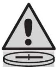
- INGESTION HAZARD: This product contains a button cell or coin battery.
- DEATH or serious injury can occur if ingested.
• A swallowed button cell or coin battery can cause Internal Chemical Burns in as little as 2 hours. - KEEP new and used batteries OUT OF REACH of CHILDREN.
- Seek immediate medical attention if a battery is suspected to be swallowed or inserted inside any part of the body.
- Remove and immediately recycle or dispose of used batteries according to local regulations and keep away from children. Do NOT dispose of batteries in household trash or incinerate.
• Even used batteries may cause severe injury or death. - Call a local poison control center for treatment information.
- Battery Type: CR2032 and Nominal Battery Voltage: 3V.
• Non-rechargeable batteries are not to be recharged. - Do not force discharge, recharge, disassemble, heat above 40^ or incinerate. Doing so may result in injury due to venting, leakage or explosion resulting in chemical burns.
- Ensure the batteries are installed correctly according to polarity (+ and -).
- Do not mix old and new batteries, different brands or types of batteries, such as alkaline, carbon-zinc, or rechargeable batteries.
- Remove and immediately recycle or dispose of batteries from equipment not used for an extended period of time according to local regulations.
• Always completely secure the battery compartment. If the battery compartment does not close securely, stop using the product, remove the batteries, and keep them away from children.
text_image
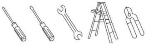
Warning symbol with exclamation mark and plus sign, commonly used in safety or hazard prevention contextTOOLS AND MATERIALS REQUIRED
• Phillips Screwdriver
- Blade Screwdriver
- 11 mm Wrench
- Step Ladder
- Wire Cutters

natural_image
Line drawings of five different tools: screwdriver, wrench, ladder, pliers, and flatener (no text or symbols)PACKAGE CONTENTS
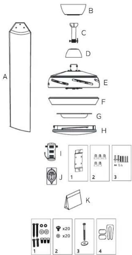
Unpack your fan and check the contents. You should have the following items:
A. Fan Blades (6)
B. Canopy & Ceiling Mounting Bracket
C. Ball/Downrod Assembly
D. Coupling Cover
E. Fan Motor Assembly
F. Mounting Plate
G. Light Kit
H. Diffuser
I. Receiver
J. Transmitter (371075) and Wall Plate
1) Metal Plate (1)
2) Wire Nuts (5)
3) Plastics Plugs (2), Screws (2)
Wood Screws (2), Screws (2)
Plastic Plugs (2)
K. Part Bag Contents
1)Mounting hardware:
Flat Washers (2), Wood Screws (2)
Star Washers (2), Wire Nuts (3),
Screws (2)
2) Blade Attachment Hardware:
Blade Mounting Screws (20),
Fiber Washers (20)
3) Safety Cable Hardware:
Wood Screw (1), Flat Washer (1)
4) Balance Kit
text_image
A B C D E F G H I J 1 2 3 K 1 2 3 4MOUNTING OPTIONS
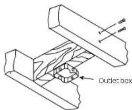
If there is not an existing UL (cUL for Canadian Installation) listed mounting box, then read the following instructions. Disconnect the power by removing fuses or turning off circuit breakers.
Secure the outlet box directly to the building structure. Use appropriate fasteners and building materials. The outlet box and its support must be able to fully support the full weight of the fan (up to 15.9kg (35 pounds)). Do not use plastic outlet boxes.
Figures 1, 2 and 3 are examples of different ways to mount the outlet box.
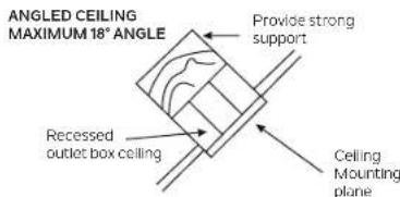
NOTE: If you are installing the ceiling fan on a sloped (vaulted) ceiling, you may need a longer downrod to maintain proper clearance between the tip of the blade and the ceiling. A minimum clearance of 12" is suggested for optimal operation.
NOTE: Depending on the location you have selected for installation, you may need to purchase and install a "Joist Hanger" for the support of the outlet box. Make sure the joist hanger you purchase has been designed for use with ceiling fans. (Fig. 4)
text_image
Outlet boxFig. 1
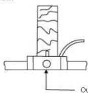
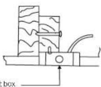
Fig. 2
text_image
ANGLED CEILING MAXIMUM 18° ANGLE Provide strong support Recessed outlet box ceiling Ceiling Mounting planeFig. 3
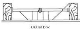
Fig. 4
HANGING THE FAN
CAUTION: To avoid possible electrical shock, be sure you have turned off the power at the main circuit panel.
REMEMBER to turn off the power before you begin installation. This is necessary for your safety.
WARNING: All set screws must be checked, and retightened where necessary, before installation.
To properly install your ceiling fan, follow the steps below.
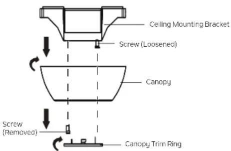
Step 1. Remove the canopy trim ring from the canopy by turning the canopy trim ring counter clockwise. (Fig. 5)
Step 2. Remove the canopy from the ceiling mounting bracket by loosening the screw in the keyhole slot by a half turn, removing (and saving) the screw from the round hole, then rotating the canopy (counterclockwise). (Fig. 5)
Step 3. Pass the 120 volt supply wires from the ceiling outlet box through the center of the ceiling mounting bracket. (Fig. 6)
Step 4. Attach the ceiling mounting bracket to the outlet box using the mounting screws and washers included with the outlet box. (Fig. 6)
text_image
Ceiling Mounting Bracket Screw (Loosened) Canopy Screw (Removed) Canopy Trim RingFig. 5

text_image
dULus Outlet Box Ceiling Mounting Bracket Washer (Supplied with Outlet Box) Mounting Screw (Supplied with Outlet Box) 120V Wires Ground Wire Washer (Supplied with Outlet Box) Mounting Screw (Supplied withFig. 6
HANGING THE FAN (continued)
WARNING: All set screws must be checked, and retightened where necessary, before installation.
Step 5. Remove the retaining clip and the hitch pin from the ball/downrod assembly. Remove the ball from the ball/downrod assembly by loosening the set screw (do not remove) on the ball, unscrewing and removing the cross pin, and unscrewing the ball from the downrod. (Fig. 7)
Step 6. Loosen the two set screws (do not remove) in the coupling on top of the motor. (Fig. 8)
Step 7. Carefully feed the wires and safety cable from the coupling on top of the motor assembly up through the downrod. (Fig. 8)
Step 8. Thread the downrod into the coupling on top of the motor assembly until the hitch pin holes in the downrod and the hitch pin holes in the coupling are aligned. Carefully insert the hitch pin through the holes in the coupling and the downrod. (Fig. 8)
NOTE: Be careful not to jam the hitch pin against the wiring inside of the downrod.
Insert the retaining clip through the hole in the hitch pin until it snaps into its locked position. (Fig. 8)
Step 9. Tighten the two set screws in the coupling on top of the motor assembly firmly. (Fig. 8)
Step 10. Carefully slip the coupling cover, canopy trim ring (smooth finished side facing motor body), and canopy onto the downrod. (Fig. 8)
Carefully thread the ball onto the downrod. Insert the cross pin through the ball and downrod and tighten. (Fig. 9)
NOTE: Be careful not to jam the cross pin against the wiring inside of the downrod.
Tighten the set screw on the ball. Make sure that the wires are not twisted. (Fig. 9)
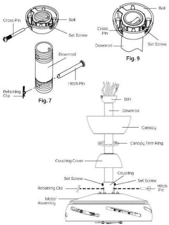
Fig. 8
HANGING THE FAN (continued)
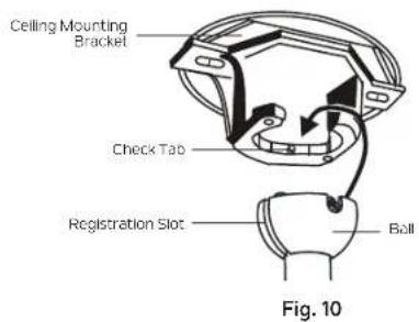
Step 11. Lift the motor assembly into position and place the ball into the ceiling mounting bracket. Rotate the entire assembly until the "Check Tab" has dropped into the "Registration Slot" and seats firmly. (Fig. 10)
The entire motor assembly should not rotate (left or right) when seated properly.
WARNING: Failure to reattach the cross pin and seat the "Check Tab" can cause the fan to fall from the ceiling during operation. Take special care to make sure this pin is reattached.
text_image
Ceiling Mounting Bracket Check Tab Registration Slot Ball Fig. 10INSTALLATION OF SAFETY Cable (required for Canadian installation ONLY)
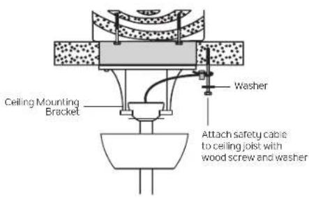
A safety support cable is provided to help prevent the ceiling fan from falling, please install it as follows.
Step 1. Slip the washer onto the wood screw. Attach the wood screw and washer to the ceiling joist next to the ceiling mounting bracket but do not tighten. (Fig. 11)
Step 2. Adjust the length of the safety cable to reach the screw and washer by pulling the extra cable through the cable clamp until the overall length is correct, put the end of the cable back through the cable clamp, forming a loop at the end of the cable. Tighten the cable clamp securely. Now, put the loop in the end of the safety cable over the wood screw and between the washer and the ceiling joist. Tighten the wood screw securely.
NOTE: Although the safety support cable is required for Canadian installations only, it's a good idea to make the attachment with any installation.
ELECTRICAL CONNECTIONS
CAUTION: To avoid possible electrical shock, be sure you have turned off the power at the main circuit panel.
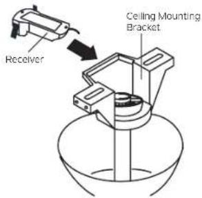
Step 1. Insert the receiver into the ceiling mounting bracket with the flat side of the receiver facing the ceiling. (Fig. 12) For best performance, make sure the black antenna wire (on the end of the receiver) remains extended, and does not become tangled with the electrical wires.
text_image
Ceiling Mounting Bracket Washer Attach safety cable to ceiling joist with wood screw and washerFig. 11
text_image
Receiver Ceiling Mounting BracketFig. 12
ELECTRICAL CONNECTIONS (continued)
WARNING: Carefully read and retain this Instruction Manual for future reference.
WARNING: To avoid possible electrical shock, be sure the electricity is turned off at the main panel by removing the fuse or opening the circuit breaker.
WARNING: This control is designed for use with "DC Motor Ceiling Fans" ONLY. DO NOT use with any other type of electrical appliance.
WARNING: All wiring must conform to national and local electrical codes. If you feel you do not have enough electrical knowledge, have a licensed electrician install the control.
WARNING: The amperage for your fan should not exceed 1A. The total wattage for the lights 50W.
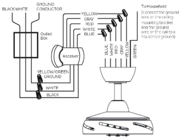
Make each of the wire connections illustrated in Fig. 13. Secure each with the wire nuts provided.
Use the wire connectors supplied with your fan. Secure the connectors with electrical tape. Make sure there are no loose wire strands or connections.
WARNING: Check to see that all connections are tight, including ground, and that no bare wire is visible at the wire connections.
After making all wire connections, turn the wire connecting nuts upward, and push the wiring into the outlet box. Separate the white (neutral) and green (ground) wire connections to the one side of the outlet box, and the black (hot) wire connections to the other side of the outlet box.
text_image
BLACK WHITE GROUND CONDUCTOR Yellow GRAY RED WHITE BLUE Outlet Box Receiver YELLOW/GREEN GROUND WHITE BLACK BLUE WHITE RED GRAY YELLOW GREEN To Household (Connect the ground wine on the ceiling mounting bracket and the ground wire on the ball to a household ground)Fig. 13
ELECTRICAL CONNECTIONS (continued)
A. CEILING FAN TO RECEIVER WIRE CONNECTION
Step 1. Connect the Blue wire from the fan (motor) to the Blue wire from the receiver. White wire from the fan (motor) to the White wire from the receiver. Red wire from the fan (motor) to the Red wire from the receiver. Gray wire from the fan (motor) to the Gray wire from the receiver. Yellow wire from the fan (motor) to the Yellow wire from the receiver. (Fig. 13)
B. RECEIVER TO HOUSEHOLD WIRE CONNECTION
WARNING: If your house wires are in different colors than referenced in this manual, stop immediately. A professional electrician is recommended.
Step 1. The black wire of the receiver (AC IN L) connects to the black wire (HOT) of the ceiling outlet box (Fig. 13).
Step 2. The white wire (AC IN N) of the receiver connects to the white wire (NEUTRAL) of the ceiling outlet box (Fig. 13).
Step 3. The ground wire (yellow/green) of the receiver connects to the ground conductor of the ceiling outlet box (Fig. 13).
NOTE: If a household ground is not available, consult a Certified Electrician before proceeding.
C. CEILING MOUNTING BRACKET AND BALL TO HOUSEHOLD WIRE CONNECTION
Step 1. The ground wire (green) of the ceiling mounting bracket and the ground wire (green) of the ball connects to the ground conductor of the ceiling outlet box (Fig. 13).
NOTE: If a household ground is not available, consult a Certified Electrician before proceeding.

text_image
BLACK WHITE GROUND CONDUCTOR Yellow GRAY RED WHITE BLUE Outlet Box Receiver YELLOW/GREEN GROUND WHITE BLACK BLUE WHITE RED GRAY YELLOW GREEN To Household (Connect the ground wire on the ceiling mounting bracket and the ground wire on the ball to a household ground)Fig. 13
FINISHING THE MOTOR INSTALLATION
CAUTION: To avoid possible electrical shock, be sure you have turned off the power at the main circuit panel.
Step 1. Tuck all the connections neatly into the ceiling outlet box.
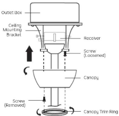
Step 2. Carefully raise the canopy up to the ceiling mounting bracket and place the keyhole slot in the canopy over the screw head on the ceiling mounting bracket. Rotate the canopy (clockwise) until it locks in place against the screw at the narrow section of the keyhole slot. (Fig. 14)
Step 3. Align the remaining circular hole in the canopy with the remaining hole in the ceiling mounting bracket. Reinstall the screw that was removed earlier (HANGING THE FAN: Page 9, Step 2, Fig. 5) into the aligned holes. Tighten both screws to secure. Attach the canopy trim ring to the screw heads by carefully raising the canopy trim ring up to the canopy (placing the keyhole slots in the canopy trim ring over the screw heads on the canopy) then rotating the canopy trim ring (clockwise) until it locks in place against the screws at the narrow sections of the keyhole slots to secure.
NOTE: Adjust the screws as necessary until the canopy and canopy trim ring are snug. (Fig. 14)
WARNING: Make sure the "Check Tab" at the bottom of the ceiling mounting bracket is properly seated in the "Registration Slot" on the side of the hanger ball before attaching the canopy to the ceiling mounting bracket. Failure to properly seat the "Check Tab" could damage the electrical wires when ceiling fan blade direction is changed while the fan is running.
text_image
Outlet Box Ceiling Mounting Bracket Receiver Screw (Loosened) Canopy Screw (Removed) Canopy Trim RingFig. 14
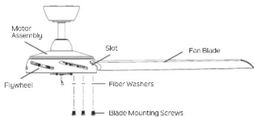
ATTACHING THE FAN BLADES
CAUTION: To reduce the risk of electric shock, disconnect the electrical supply circuit to the fan before installing the fan blades.
Step 1. Insert fan blade through a slot in the flywheel. (Fig. 15)
Align the holes in the fan blade with the holes in the flywheel and attach the fan blade to the flywheel with three fiber washers and three blade mounting screws. Tighten blade mounting screws to secure.
Step 2. Repeat for the remaining fan blades. (Fig. 15)
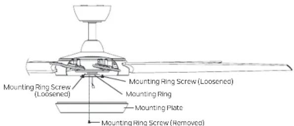
INSTALLING THE MOUNTING PLATE
CAUTION: To reduce the risk of electric shock, disconnect the electrical supply circuit to the fan before installing the mounting plate.
Step 1. Loosen two of the mounting ring screws on the mounting ring attached to the motor shaft, and remove and save the third mounting ring screw. (Fig. 16)
Step 2. Place the key holes in the mounting plate over the 2 mounting ring screws that were loosened on the mounting ring, and turn mounting plate (clockwise) until it locks in place against the mounting ring screws at the narrow sections of the key holes. (Fig. 16)
Replace the third mounting ring screw that was previously removed, and tighten all 3 mounting ring screws to secure. (Fig. 16)
text_image
Motor Assembly Slot Fan Blade Flywheel Fiber Washers Blade Mounting ScrewsFig. 15
text_image
Mounting Ring Screw (Loosened) Mounting Ring Screw (Loosened) Mounting Ring Mounting Plate Mounting Ring Screw (Removed)Fig. 16
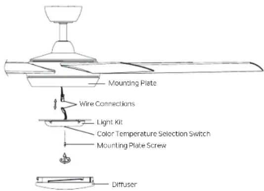
SELECTING LED COLOR TEMPERATURE AND INSTALLING THE LIGHT KIT AND DIFFUSER
CAUTION: To reduce the risk of electric shock, disconnect the electrical supply circuit to the fan before selecting LED color temperature and before installing the light kit and diffuser.
Step 1. Locate the color temperature selection switch on the light kit, and select the desired LED color temperature (CCT1 = 3000K soft white, CCT2 = 5000K daylight) (Fig. 17)
Step 2. Loosen two of the mounting plate screws on the mounting plate, and remove and save the third mounting plate screw. (Fig. 18)
Step 3. While holding the light kit under your ceiling fan, push the square wire connectors together. One from the fan and one from the light kit. (Fig. 18)
NOTE: The connectors will ONLY engage when the shapes of the connectors are matched. (aligned)
Step 4. Tuck the connections neatly into the mounting plate. Place the keyhole slots in the light kit over the 2 mounting plate screws that were loosened from the mounting plate, and turn the light kit (clockwise) until it locks in place against the mounting plate screws at the narrow sections of the keyhole slots.
Replace the third mounting plate screw that was previously removed, and tighten all 3 mounting plate screws to secure. (Fig. 18)
Step 5. Raise the diffuser up to the fan, seat against the mounting plate, and turn (clockwise) into the mounting plate until snug, DO NOT OVER TIGHTEN. (Fig. 18)

Fig. 17
text_image
Mounting Plate Wire Connections Light Kit Color Temperature Selection Switch Mounting Plate Screw DiffuserFig. 18
CAUTION: To avoid possible electrical shock, be sure you have turned off the power at the main circuit panel.
WARNING: All wiring must be in accordance with the National Electrical Code and local electrical codes. Electrical installation should be performed by a qualified licensed electrician.
Select a location to install your CoolTouch® wall plate. You can replace an existing wall switch, or install the wall plate on ANY flat surface.
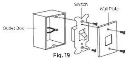
Option 1: Install the wall plate using an existing wall switch outlet box.
CAUTION: Switch installation must comply with all local and national electric code. Make sure the electrical power is TURNED OFF at the main panel before continuing.
Step 1. Remove the existing wall plate and the old switch from the wall outlet box. Wire nut the BLACK leads (hot) together and push back inside the outlet box. (Fig. 19)
Step 2. Install the metal plate and CoolTouch® wall plate to the existing wall outlet box with 4 screws provided. Insert the two plastic plugs into the wall plate. (Fig. 20A)
Option 2: Install the wall plate on ANY flat surface.
Step 1. Select the desired location and use the CoolTouch wall plate to mark the location for the mounting holes.
Step 2. Use the drywall anchors and screws provided to finish the installation. (Fig. 20B)
INSTALLING THE TRANSMITTER
Step 1. Insert the transmitter into the wall plate by inserting the bottom of the transmitter first and then pressing the top of the transmitter into the pocket. The transmitter will fully function from this location or you can remove the transmitter and use it as a hand held device. (Fig. 21)
Step 2. To remove the transmitter from the wall plate, push the release button and the transmitter will fall into your hand.
text_image
Outlet Box Switch Wall Plate Fig. 19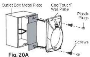
text_image
Outlet Box Metal Plate Cool Touch Wall Plate Plastic Plugs Screws Fig. 20A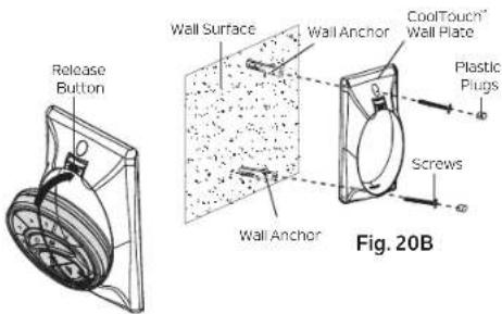
text_image
Release Button Wall Surface Wall Anchor CoolTouch® Wall Plate Plastic Plugs Screws Wall Anchor Fig. 20BFig. 21
OPERATING INSTRUCTIONS
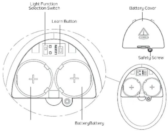
ACTIVATING THE TRANSMITTER BATTERIES AND ACTIVATING THE TRANSMITTER (Fig. 22A)

WARNING: Chemical Burn Hazard. Keep batteries away from children. This product contains a lithium button/coin cell battery. If a new or used lithium button/coin cell battery is swallowed or enters the body, it can cause severe internal burns and can lead to death in as little as 2 hours. Always completely secure the battery compartment. If the battery compartment does not close securely, stop using the product, remove the batteries, and keep it away from children. If you think batteries might have been swallowed or placed inside any part of the body, seek immediate medical attention. a) The cells shall be disposed of properly, including keeping them away from children; and b) Even used cells may cause injury.
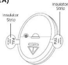
Step 1. To activate the transmitter, carefully pull the insulator strips out of the transmitter to activate the two preinstalled CR2032 3V button/coin cell batteries. Discard insulator strips. (Fig. 22A)
NOTE: To prevent damage to the transmitter, remove the batteries if not in use for long periods of time (months).
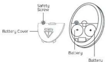
To remove the batteries, loosen the safety screw and remove the battery cover from the back of the transmitter to access the battery compartment. (Fig. 22B)
Remove the batteries, then reinstall the battery cover to the back of the transmitter and tighten the safety screw.
text_image
Insulator Strip Insulator Strip FULLFig. 22A
text_image
Safety Screw Battery Cover Battery BatteryFig. 22B
OPERATING INSTRUCTIONS (continued)
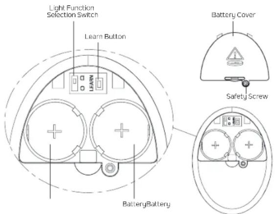
LIGHT FUNCTION SELECTION SWITCH (Fig. 23)
The light function selection switch is located inside of the transmitter (under the battery cover). (Fig. 23)
To access the light function selection switch (if needed), loosen the safety screw, and remove the battery cover from the back of the transmitter. After adjustment is complete, reinstall the battery cover to the back of the transmitter and tighten the safety screw.
D="Dimming"
O="Only on/off, no dimming"
NOTE: The switch has been factory set to "D".
NOTE: If the LED light kit included with this fan is installed to the fan, the switch should always be set to "D".
NOTE: If a dimmable LED light kit is installed to this fan, the switch should always be set to "D".
NOTE: The "Only on/off, no dimming" setting is intended for use with non-dimmable LED light kits/lamps, and light kits that have fluorescent lamps.
WARNING: If the "D/O" switch is not set correctly, the lighting control system will operate erratically and could damage your ceiling fan.
text_image
Light Function Selection Switch Learn Button LEARN Battery Cover Safety Screw BatteryBatteryFig. 23
OPERATING INSTRUCTIONS (continued)
PAIRING THE TRANSMITTER TO THE FAN (Fig. 23)
WARNING: Make sure the power is completely disconnected at the circuit breaker or fuse box before you begin this process.
IMPORTANT: Fan motor and fan blades MUST be installed before pairing process can begin.
NOTE: Your transmitter has been paired to your fan's receiver at the factory. No frequency change is necessary. If the fan is non-functional or if you would like to install an additional fan with a separate frequency code, follow Steps 1-4 to pair a transmitter to a receiver.
Step 1. Loosen the safety screw, and remove the battery cover from the back of the transmitter.
Step 2. Restore power to the ceiling fan branch circuit at the circuit breaker or fuse box. Within 30 seconds of restoring power, press and hold the "LEARN" button on the back of the transmitter (Fig. 23) for 3 seconds. The fan will turn on at medium speed. This confirms that the pairing process is complete. The transmitter will now be paired to your fan and ready for use.
Step 3. Reinstall the battery cover to the back of the transmitter and tighten the safety screw.
Step 4. Try different speed settings on the transmitter to make sure the fan is fully functional. If programming is unsuccessful, completely disconnect power at the circuit breaker or fuse box again, then retry Steps 1-3 again.
NOTE: Please keep this page in case future reprogramming is needed, or an additional transmitter is added.
text_image
Light Function Selection Switch Learn Button LEARN Battery Cover Safety Screw BatteryBatteryFig. 23
OPERATING INSTRUCTIONS (continued)
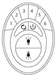
TRANSMITTER OPERATION (Fig. 24)

OFF Button
Press once to stop the fan.

Fan speed control buttons
1 is the lowest speed and 6 is the highest speed. Press one of the buttons to start the fan at the corresponding speed, or to change speeds.

Light Buttons

Press either button to control the light kit on the fan.

Press once to turn the light on or off
DIMMING: Press and hold to dim or brighten the light to desired level, then release.
Reverse Button

While the fan is running, press the reverse button once, and the fan will reverse direction.
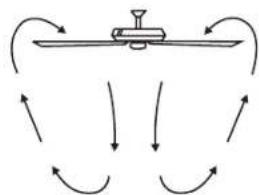
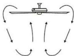
REVERSE FUNCTION
To operate the reverse function on this fan, press the "Reverse" button on transmitter while fan is running.
Warm weather - "FORWARD" (fan rotates counterclockwise) A downward airflow creates a cooling effect as shown in (Fig. 25). This allows you to set your air conditioner on a warmer setting without affecting your comfort.
Cool weather - "REVERSE" (fan rotates clockwise) An upward airflow moves warm air off the ceiling area as shown in (Fig. 26). This allows you to set your heating unit on a cooler setting without affecting your comfort.
text_image
1 2 3 4 5 6 1 2 3 4 5 6Fig. 24
natural_image
Diagram of a mechanical lever system with curved arrows indicating motion or force direction (no text or symbols)Fig. 25
flowchart
graph TD
    A["Start"] --> B{Process}
    B -->|Yes| C["Loop 1"]
    B -->|No| D["Loop 2"]
    C --> E["End"]
    D --> E
    E --> F["Feedback Loop"]
    F --> A
Fig. 26
TROUBLESHOOTING
Problem SolutionSolution
Fan will not start. 1. Check circuit fuses or breakers.
- Ensure that the batteries in the transmitter are installed properly with the +side facing up, and that they still have power. NOTE: When a button is pressed on the transmitter, the backlight in the transmitter will light up if the batteries still have power.
- Check all electrical connections to ensure proper contact. CAUTION: Make sure the main power is OFF when checking any electrical connection.
Fan sounds noisy. 1. Make sure all motor housing screws are snug.
- Make sure the screws that attach the fan blade brackets to the motor are tight.
- Make sure wire nut connections are not rubbing against each other or the interior wall of the switch housing. CAUTION: Make sure main power is off.
- Allow a 24-hour "breaking-in" period. Most noise associated with a new fan will disappear during this time.
- If using an optional light kit, make sure the screws securing the glassware are tight. Make sure the light bulbs are not touching any other component.
- Do not connect this fan to wall mounted variable speed control(s). They are not compatible with ceiling fan motors or remote controls.
- Make sure the upper canopy is a short distance from the ceiling. It should not touch the ceiling.
TROUBLESHOOTING (continued)
Problem
SolutionSolution
Fan wobble.
- Check that all blade and blade arm screws are secure.
- Most fan wobbling problems are caused when blade levels are unequal. Check this level by selecting a point on the ceiling above the tip of one of the blades. Measure this distance. Rotate the fan until the next blade is positioned for measurement. Repeat for each blade. The distance deviation should be equal within 1/8".
- If the blade wobble is still noticeable, interchanging two adjacent (side by side) blades can redistribute the weight and possibly result in smoother operation.
Remote control malfunction.
- Ceiling Fans with remote control systems CAN NOT be operated in conjunction with any other control system EXCEPT a basic On/Off wall switch if desired.
WARNING: TO REDUCE THE RISK OF PERSONAL INJURY AND TO ENSURE THE PROPER OPERATION OF YOUR CEILING FAN, NEVER ATTACH THE BLADE ASSEMBLIES UNTIL THE CEILING FAN HAS BEEN MOUNTED ON THE CEILING. DO NOT BEND THE BLADES WHILE INSTALLING, BALANCING OR CLEANING THE FAN. DO NOT INSERT FOREIGN OBJECTS BETWEEN ROTATING FAN BLADES.
FCC INFORMATION
This device complies with part 15 of the FCC Rules. Operation is subject to the following two conditions:
1) This device may not cause harmful interference, and
2) This device must accept any interference received, including interference that may cause undesired operation.
Note: This equipment has been tested and found to comply with the limits for a Class B digital device, pursuant to part 15 of the FCC Rules. These limits are designed to provide reasonable protection against harmful interference in a residential installation. This equipment generates, uses and can radiate radio frequency energy and, if not installed and used in accordance with the instructions, may cause harmful interference to radio communications. However, there is no guarantee that interference will not occur in a particular installation. If this equipment does cause harmful interference to radio or television reception, which can be determined by turning the equipment off and on, the user is encouraged to try to correct the interference by one or more of the following measures:
- Reorient or relocate the receiving antenna.
- Increase the separation between the equipment and receiver.
- Connect the equipment into an outlet on a circuit different from that to which the receiver is connected.
- Consult the dealer or an experienced radio/TV technician for help.
KICHLER®
www.kichler.com
KICHLER LIGHTING LLC
30455 SOLON RD.
SOLON, OH 44139 USA
CUSTOMER SERVICE 866.558.5706
8:00 AM TO 5:00 PM EST, MONDAY - FRIDAY
REV 5-AUG-2024
© Kichler Lighting LLC. All Rights Reserved.
KICHLER®
Mint de 60 po
natural_image
Line drawing of a five-blade ceiling fan with no text or symbolsMANUEL D'INSTRUCTIONS
text_image
Warning symbol with exclamation mark inside triangle and plus/minus signs below, indicating caution or hazard levelOUTILS ET MATÉRIAUX NÉCESSAIRES
• Tournevis cruciforme
- Tournevis plat
- Clé de 11 mm
- Escabeau
- Coupe-fils
natural_image
Line drawings of five different tools: screwdriver, wrench, ladder, pliers, and flatener (no text or symbols)CONTENU DU COLIS
text_image
A B C D E F G H I J 1 2 3 K 1 2 3 4OPTIONS DE MONTAGE
natural_image
Pure diagram of a mechanical or fluidic system with curved arrows indicating direction (no text or symbols)Fig. 25

flowchart
graph TD
    A["Start"] --> B{Process}
    B -->|Yes| C["Loop 1"]
    B -->|No| D["Loop 2"]
    C --> E["End"]
    D --> E
    E --> F["Feedback Loop"]
    F --> A
Fig. 26
DÉPANNAGE
Problème
SolutionSolution
natural_image
Line drawing of a five-blade ceiling fan with no text or symbolstext_image
Warning symbol with exclamation mark inside triangle and plus/minus signs below, indicating caution or hazard levelHERRAMIENTAS Y MATERIALES REQUERIDOS
natural_image
Line drawings of five different tools: screwdriver, wrench, ladder, pliers, and flatener (no text or symbols)text_image
A B C D E F G H I J 1 2 3 K 1 2 3 4OPCIONES DE MONTAJE
natural_image
Diagram of a mechanical lever system with curved arrows indicating motion, labeled Figura 25 (no text or symbols on the diagram itself)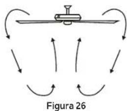
flowchart
graph TD
    A["Start"] --> B{Condition}
    B -->|Yes| C["Process Unit"]
    B -->|No| D["End"]
    C --> E["Output"]
    D --> E
    style A fill:#f9f,stroke:#333
    style E fill:#bbf,stroke:#333