Pinion - Fan Kichler - Free user manual and instructions
Find the device manual for free Pinion Kichler in PDF.

User questions about Pinion Kichler
0 question about this device. Answer the ones you know or ask your own.
Ask a new question about this device
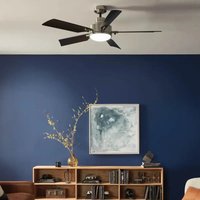
Download the instructions for your Fan in PDF format for free! Find your manual Pinion - Kichler and take your electronic device back in hand. On this page are published all the documents necessary for the use of your device. Pinion by Kichler.
USER MANUAL Pinion Kichler
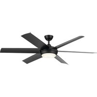
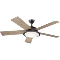
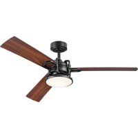
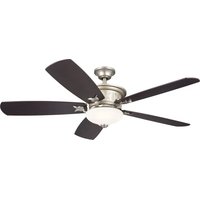
Product images may vary slightly from actual product.
natural_image
Black and white photo of a modern black-and-white ceiling fan with three blades (no text or symbols visible)INSTRUCTION MANUAL
TABLE OF CONTENTS
SAFETY RULES 3
TOOLS REQUIRED 4
PACKAGE CONTENTS 4
MOUNTING OPTIONS 5
INSTALLING THE TOP HOUSING 6
HANGING THE FAN 8
INSTALLATION OF SAFETY SUPPORT ....9
ELECTRIC CONNECTIONS 10
WIRE DIAGRAM 11
FINISHING THE INSTALLATION .... 12
ATTACHING THE FAN BLADES 13
INSTALLING THE LOWER HOUSING....13
INSTALLING THE SWITCH HOUSING 13
INSTALLING THE WALL CONTROL 16
CONTROL SYSTEM SET-UP 17
OPERATING INSTRUCTIONS 17
TROUBLESHOOTING....18
FCC WARNING....19
SAFETY RULES READ AND SAVE THESE INSTRUCTIONS
- To reduce the risk of electric shock, insure electricity has been turned off at the circuit breaker or fuse box before beginning.
- All wiring must be in accordance with the Nation Electrical Code and local electrical codes. Electrical installation should be performed by a qualified licensed electrician.
- WARNING: To reduce the risk of fire or electric shock, use only the control provided with the fan.
- WARNING: To reduce the risk of fire, electric shock, or Personal Injury, mount directly to a structural framing member or to an outlet box marked "Acceptable for Fan Support of 15.9kg(35 lbs)or less". For outlet box mounting, use mounting screws provided with the outlet box.
- To operate the reverse function on this fan, press the reverse button while the fan is running.
- Avoid placing objects in the path of the blade
-
To avoid personal injury or damage to the fan and oth items, be cautious when working around or cleaning the fan.
-
The fan must be mounted with a minimum of 2.13 m (7 ft.) from the floor and 76 cm (30 in.) from any wall or obstruction.
- Do not use water or detergents when cleaning the fan or fab blades. A dry dust cloth or lightly dampened cloth will be suitable for most cleaning.
- After making the electrical connections, spliced conducto should be turned upward and pushed carefully up into outlet box. The wires should be spread apart with the ground wire and white (common) wire to one side with the black (load) wire to the other side of the outlet box.
- Electrical diagrams are reference only. Light kits that are n packed with the fan must be ETL Listed and marked suitable for use with the model fan you are installing. Switches must be ETL General Use Switches. Refer to the Instructions packaged with the light kits and switches for proper assembly.
WARNING
TO REDUCE THE RISK OF PERSONAL INJURY, DO NOT BEND THE BLADE BRACKETS (ALSO REFERRED TO AS FLANGES) DURING ASSEMBLY OR AFTER INSTALLATION. DO NOT INSERT OBJECTS IN THE PATH OF THE BLADES.
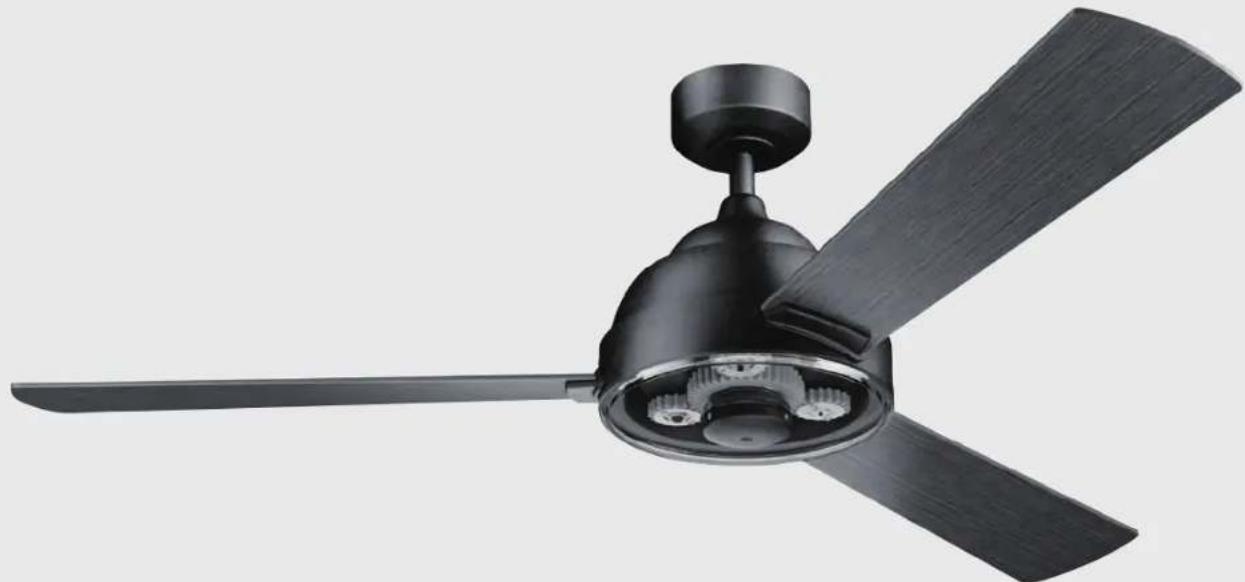
TOOLS REQUIRED
- Phillips screwdriver
- Blade screwdriver
- 11 mm wrench
- Step ladder
- Wire cutters
natural_image
Line drawings of five different types of screwdrivers and pliers, no text or symbols presentPACKAGE CONTENTS
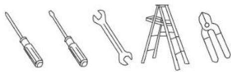
Unpack your fan and check the contents. You should have the following items:
A. Mounting bracket
B. Ball / downrod assembly
C. Canopy
D. Canopy Hole Cover
E. Coupling Cover
F. Top Housing
G. Motor Body
H. Fan Blade (3)
I. Lower Housing
J.Switch Housing
K.Switch Housing Cover
L. Wall Control System
M. Package hardware
1) Mounting hardware :
Wire Connector (3)
2) Blade attachment hardware :
Screws (9), washer (9)
3) Safety cable hardware :
Wood screw (1), Spring washer (1).
Flat washer (1)
4) Top housing hardware: screw (3)
text_image
A B C D E F G H I J K L x11 x2 MMOUNTING OPTIONS
If there isn't an existing UL (cUL for Canadian Installation) listed mounting box, then read the following instructions. Disconnect the power by removing fuses or turning off circuit breakers.
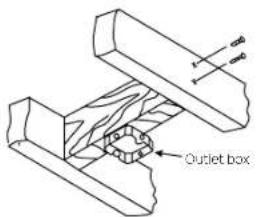
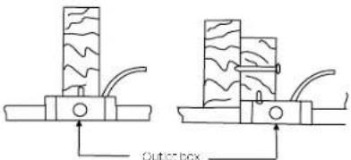
Secure the outlet box directly to the building structure. Use appropriate fasteners and building materials. The outlet box and its support must be able to fully support the moving weight of the fan (at least 50 lbs). Do not use plastic outlet boxes.
Figures 1, 2 and 3 are examples of different ways to mount the outlet box.
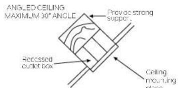
NOTE: If you are installing the ceiling fan on a sloped (vaulted) ceiling, you may need a longer downrod to maintain proper clearance between the tip of the blade and the ceiling. A minimum clearance of 12" is suggested for optimal operation.
NOTE: You must use 12" or longer downrod for 30° slope (max angle 30°). (Fig. 3)
NOTE: Depending on the location you have selected for installation, you may need to purchase and install a "Joist Hanger" for the support of the outlet box. Make sure the joist hanger you purchase has been designed for use with ceiling fans. (Fig. 4)
text_image
Outlet boxFig. 1
text_image
Outer boxFig. 2
text_image
ANGLED CEILING MAXIMUM 30° ANGLE Prevoc strong support Recessed outlet box Ceiling mounting planeFig. 3
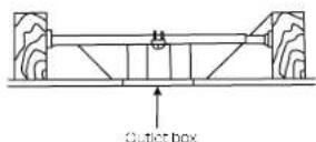
Fig. 4
INSTALLING THE TOP HOUSING
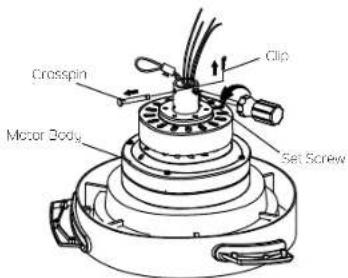
Step 1. Remove the clip, cross pin and two set screws from the top coupling of the motor body, and save for later use on step 4. (Fig. 5)
Step 2. Carefully feed the fan wires up through the center hole of top housing, place the top housing over the motor body and align the holes. Insert three (3) screws from the hardware pack into the holes and securely tighten them. (Fig.6)
text_image
Crosspin Motor Body Clip Set ScrewFig. 5

text_image
Screw (5) Top HousingFig. 6
INSTALLING THE TOP HOUSING(continued)
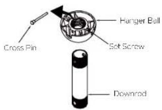
Step 3. Remove the hanger ball from downrod assembly by loosening set screws, removing the cross pin, and sliding ball off the rod.(Fig. 7)
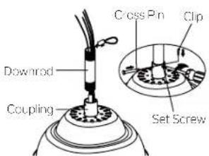
Step 4. Carefully feed the fan wires and safety cable up through the downrod. Thread the downrod onto the motor coupling until the cross pin holes are aligned. Next, replace the cross pin and clip, and tighten both set screws. (Fig. 8)
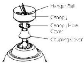
Step 5. Slip the coupling cover, canopy hole cover and canopy onto the downrod. Carefully reinstall the hanger ball onto the downrod. Make sure the cross pin is in the correct position and the set screw is tight and the wires are not twisted. (Fig. 9)
text_image
Cross Pin Hanger Ball Soft Screw DownrodFig. 7
text_image
Cross Pin Clip Downrod Coupling Set ScrewFig. 8
text_image
Hanger Ball Canopy Canopy Hole Cover Coupling CoverFig. 9
HANGING THE FAN
REMEMBER to turn off the power before you begin installation. This is necessary for your safety and also the proper programming of the control system. To properly install your ceiling fan, follow the steps below.
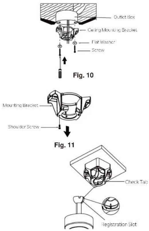
Step 1. Before attaching fan to outlet box (not included), ensure the outlet box is securely fastened to at least two points to a structural ceiling member (a loose box will cause the fan to wobble). Pass the 120 volt supply wires from the ceiling outlet box through the center of the ceiling mounting bracket. Install mounting bracket to outlet box in ceiling using the screws and washers included with the outlet box. (Fig.10)
Step 2. Remove one of the two shoulder screws in the mounting bracket, and keep for use on Page 12 Step 2. Loosen the second shoulder screw without fully removing it. (Fig. 11)
Step 3. Now lift the motor body into position and place the hanger ball into the hanger bracket. Rotate until the "Check Tab" has dropped into the "Registration Slot" and seats firmly. The entire motor body should not rotate if this is done correctly. (Fig. 12)
WARNING: Failure to properly seat the "Check Tab" can damage the ceiling fan during operation.
text_image
Outlet Box Ceiling Mounting Bracket Flat Washer Screw Fig. 10 Mounting Bracket Shoulder Screw Fig. 11 Check Tab Registration SlotFig. 12
INSTALLATION OF SAFETY SUPPORT (required for Canadian installation ONLY)
A safety support cable is provided to help prevent the ceiling fan from falling, please install it as follows.
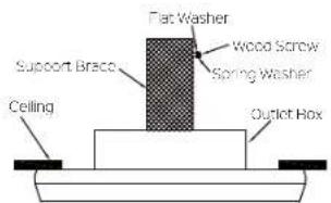
Step 1. Drive a wood screw and washers into the side of the brace that holds the outlet box. Leave 3mm (1/8") of space between the support brace and the washer. (Fig. 13)
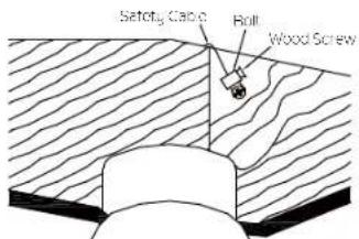
Step 2. Insert the safety cable through the mounting bracket and one of the holes in the outlet box into the ceiling. Adjust the length of the safety cable to reach the screw and washers by pulling the extra cable through the cable clamp until the overall length is correct, put the end of the cable back through the cable clamp, forming a loop at the end of the cable. Tighten the cable clamp securely. Now, put the loop in the end of the safety cable over the wood screw and under the washer. Tighten the wood screw securely. (Fig. 14)
NOTE: Although the safety support cable is required for Canadian installations only. It's a good idea to make the attachment with any installation.
text_image
Flat Washer Wood Screw Spring Washer Support Brace Ceiling Outlet BoxFig. 13
text_image
Satoty Calc Roll Wood ScrewFig. 14
ELECTRICAL CONNECTIONS
WARNING: To avoid possible electrical shock, be sure you have turned off the power at the main circuit panel before wiring. Follow the steps below to connect the fan to your household wiring. Use the wire connecting nuts supplied with your fan. Secure the connector with electrical tape. Make sure there are no loose wire stands or connections.
WARNING: If your house wires are different colors than referenced in this manual, stop immediately. A professional electrician is recommended to determine proper wiring.
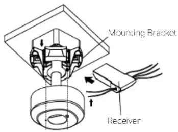
Step 1. Insert the receiver into the mounting bracket, and keep flat in opposition of ceiling. (Fig. 15)
Step 2. Motor to Receiver Electrical Connections:
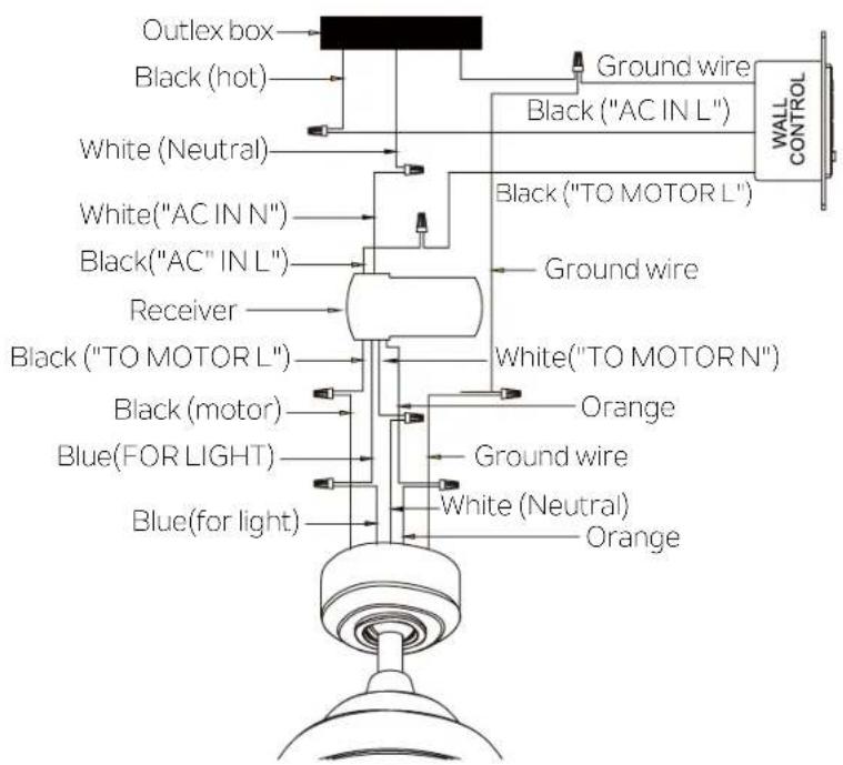
Connect the BLACK wire from the fan to BLACK wire marked "TO MOTOT L" from the receiver. Connect the WHITE wire from the fan to the WHITE wire marked "TO MOTOR N" from the receiver. Connect the BLUE wire from the fan to the BLUE wire marked "FOR LIGHT" from the receiver. Connect the ORANGE wire from the fan to the ORANGE wire from the receiver. Secure all the wire connections with the plastic wire nuts provided. (Fig. 16)
text_image
Mounting Bracket ReceiverFig. 15
Step 3. Remote Receiver to Outlet Box Electrical Connections:
Connect the BLACK (hot) wire from the ceiling to the BLACK wire marked "AC IN L" from the wall control. Connect the WHITE (Neutral) wire from the ceiling to the WHITE wire marked "AC IN N" from the receiver. Connect the BLACK (To Motor L) wire from the wall control to the BLACK wire marked "AC IN L" from the receiver. Secure the wire connections with the plastic wire connectors provided. (Fig. 16)
Step 4. Connect GROUND (GREEN) wires from hanger ball and mounting bracket, so GROUND (GREEN or BARE COPPER) from house. Secure the wire connection with a plastic connectors provided. After connecting the wires, spread them apart so that the green and white wires are on one side of the outlet box and black and blue wires are on the other side. (Fig. 16)
NOTE: Carefully tuck the wire connections up into the outlet box.
NOTE: Fan must be installed at a maximum distance of 30 feet from the transmitting unit for proper signal transmission between the transmitting unit and the fan's receiving unit.
WIRE DIAGRAM
text_image
Outlex box Black (hot) White (Neutral) White("AC IN N") Black("AC" IN L") Receiver Black ("TO MOTOR L") Black (motor) Blue(FOR LIGHT) Blue(for light) Ground wire Black ("AC IN L") Black ("TO MOTOR L") Ground wire White("TO MOTOR N") Orange Ground wire White (Neutral) Orange WALL CONTROLFig. 16
FINISHING THE INSTALLATION
NOTE: Before continuing installation, confirm that the power is still turned off at the main circuit breaker or by removing the correct fuse. Turning the power off using a wall switch is not sufficient to prevent electrical stock.
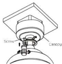
Step 1. Assemble canopy by rotating key slot in canopy over shoulder screw in mounting bracket. (Fig. 17)
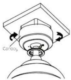
Step 2. Reinstall the shoulder screw that was previously removed on Page 8 step 2, then retighten two shoulder screws securely.(Fig.18)
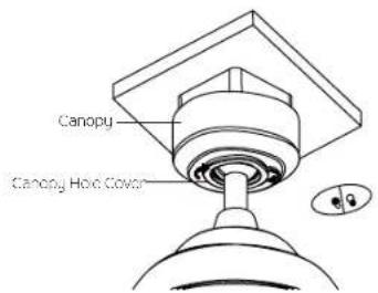
Step 3. Securely attach and tighten the canopy hole cover over the shoulder screws in the mounting bracket utilizing the keyslot twist-lock feature. (Fig. 19)
text_image
Screw CanopyFig. 18
text_image
CanopyFig. 17
text_image
Canopy Canopy Hole CoverFig. 19
ATTACHING THE FAN BLADES
NOTE: Before continuing, make sure the power is disconnected by turning off the circuit breaker of removing the fuse at the circuit box.
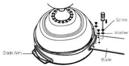
Step 1. Position the blade over the blade arm with threaded posts showing. Make sure the bottom edge of the blade is fully seated against the blade arm. With a Phillips screwdriver, start a blade screw and washer into the blade arm (do not tighten) and repeat for the 2 remaining blade screws and washers. Tighten each screw securely starting with the center screw. Make sure the blade is straight. Repeat steps for the remaining blades. (Fig. 20)
NOTE: Before continuing, make sure the power is disconnected by turning off the circuit breaker of removing the fuse at the circuit box.
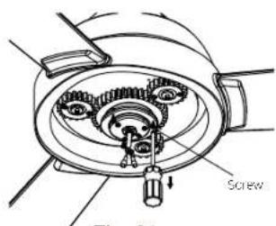
Step 1. Remove three (3) screws as shown and save for later use. (Fig. 21)
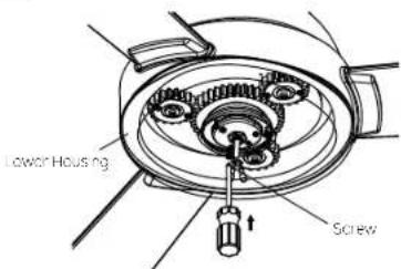
Step 2. Attach the lower housing to motor body, insert three (3) screws previously removed into the holes and securely tighten them. (Fig. 22)
text_image
Blade Arm Blade Washer ScrewFig. 20
text_image
Screw ThermostatFig. 21
text_image
Lower Housing ScrewFig. 22
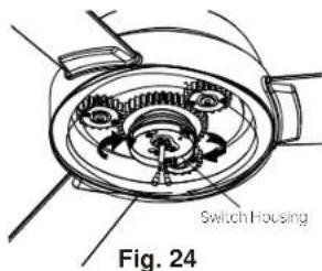
INSTALLING THE SWITCH HOUSING
NOTE: Before continuing installation, confirm that the power is still turned off at the main circuit breaker or by removing the circuit fuse. Turning the power off using a wall switch is not sufficient to prevent electrical stock.
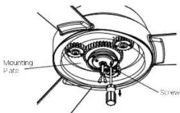
Step 1. Remove the screw marked with a dot label which preinstalled on the mounting plate and keep for later use. Loosen the other two (do not remove). (Fig. 23)
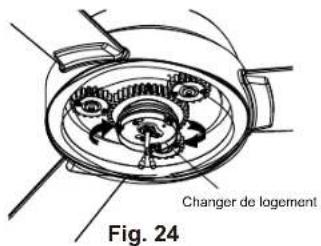
Step 2. Place the two slot holes on the switch housing over the two (2) screws previously loosened from the mounting plate. Rotate the switch housing until it locks in place at the narrowed end of the key holes. (Fig. 24)
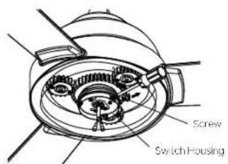
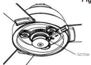
Step 3. Securely by tightening the 2 screws previously loosened and the one previously removed. (Fig. 25)
text_image
Mounting Plate ScrewFig. 23
text_image
Switch Housing Fig. 24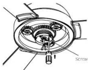
natural_image
Technical diagram of a mechanical assembly with gears and a screw (no text or symbols)Fig. 25
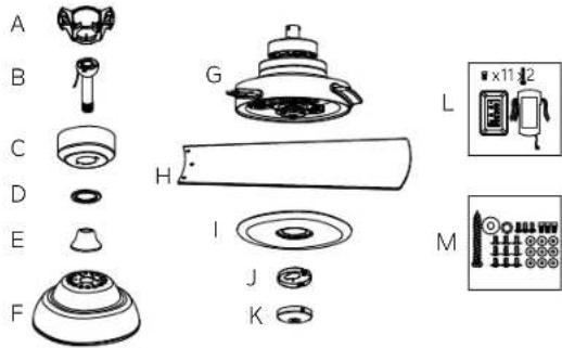
INSTALLING THE SWITCH HOUSING(continued)
Step 4. Remove three (3) screws from the switch housing as shown and save for later use. (Fig. 26)
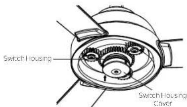
Step 5. Attach the switch housing cover to the switch housing and securely tighten with three (3) screws previously removed. (Fig. 27 & Fig. 28)
text_image
Screw Switch HousingFig. 26
text_image
Switch Housing Switch Housing CoverFig. 27
text_image
ScrewFig. 28
INSTALLING THE WALL CONTROL
All wiring must be in accordance with the National Electrical Code and local electrical codes. Electrical installation should be performed by a qualified licensed electrician. Select a location to install your wall control. You can replace an existing wall switch, or install the wall control on ANY flat surface.
NOTE: SWITCH INSTALLATION MUST COMPLY WITH ALL LOCAL AND NATIONAL ELECTRIC CODE.
WARNING: Shut off main power at the circuit breaker or fuse panel before continuing.
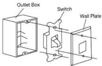
Step 1. Remove the existing wall plate and the old switch from the wall outlet box. Disconnect wires. (Fig. 29)
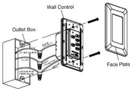
Step 2. Place the wall control to the outlet box, connect the wires with wire connectors provided. (Fig. 30)
*Connect the lead wire (HOT) from outlet box to BLACK wire marked "AC IN L" from wall control.
*Connect the lead wire (LOAD) from outlet box to BLACK wire marked "TO MOTOR L" from wall control.
*Connect the GROUND wire from outlet box to the GROUND wire from wall control.
Step 3. Secure the wires connections and make sure there are no loose strands or connections. Put wire connections back inside outlet box and secure the wall control to outlet box with screws provided. Snug the face plate to wall control. (Fig. 30)
text_image
Outlet Box Switch Wall PlateFig. 29
text_image
Wall Control Outlet Box Face PlateFig. 30
CONTROL SYSTEM SET-UP
Step 1. After installation is complete, press the LEARN button for 3 seconds within 30 seconds once AC power is turned on. Fan will turn on at medium speed and light (if installed) will turn on. This confirms that the SMART SYNC setting is active and ok. (Fig. 31)
Step 2. If you cannot finish the setting within the 30 seconds time frame, the main power must be turned off and re-started again. This will repeat step 1 until the LEARN feature is activated as indicated.
OPERATING INSTRUCTIONS
Restore power to ceiling fan and test for proper operation (Fig. 31)
- Fan Control: To start the fan. Press the selected speed button to run the fan at the desired speed: Hi-high speed; MED-medium speed; LOW-low speed; Press the "FAN OFF" button to turn off the fan.
- Light button: Press once to turn the light on or off. Continuous pressure on the light button dims light in a continuous cycle from light to dark, or dark to light.
- REV button: Controls direction, forward or reverse.
- If your ceiling fan has fluorescent lighting, please slide the switch to "O" position. If the ceiling fan has incandescent or halogen lighting or LED, please slide the switch to "D" position.
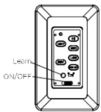
text_image
Learn ON/OFFFig. 31
TROUBLESHOOTING
| Problem | Solution |
| Fan will not start. | 1.Check circuit fuses or breakers.2.Check all electrical connections to ensure proper contact.CAUTION:Make sure the main power is OFF when checking any electrical connection.3.Make sure the transmitter batteries are installed properly. Positive (+) side facing out.4.Insure the batteries have a good charge. |
| Fan sounds noisy. | 1.Make sure all motor housing screws are snug.2.Make sure the screws that attach the fan blade brackets to the motor are tight.3.Make sure wire nut connections are not rubbing against each other or the interior wall of the switch housing.CAUTION:Make sure main power is off.4.Allow a 24-hour "breaking-in" period. Most noise associated with a new fan disappear during this time.5.If using an optional light kit, make sure the screws securing the glassware are tight.Make sure the light bulbs are not touching any other component.6.Do not connect this fan to a wall mounted variable speed control(s). They are not compatible with ceiling fan motors or remote controls.7.Make sure the upper canopy has a short distance from the ceiling. It should not touch the ceiling. |
| Fan wobble. | 1.Check that all blade and blade arm screws are secure.2.Most fan wobbling problems are caused when blade levels are unequal.Check this level by selecting a point on the ceiling above the tip of one of the blades. Measure this distance. Rotate the fan until the next blade is positioned for measurement. Repeat for each blade. The distance deviation should be equal within 1/8".3.If the blade wobble is still noticeable, interchanging two adjacent (side by side) blades can redistribute the weight and possibly result in smoother operation. |
| Remote control malfunction. | 1.Ceiling Fans with remote control systems CAN NOT be operated in conjunction with any other control system EXCEPT a basic On/Off wall switch, if desired. |
FCC WARNING
This device complies with part 15 of the FCC Rules. Operation is subject to the following two conditions:
(1) This device may not cause harmful interference, and (2) this device must accept any interference received, including interference that may cause undesired operation.
Changes or modifications not expressly approved by the party responsible for compliance could void the user's authority to operate the equipment.
NOTE: This equipment has been tested and found to comply with the limits for a Class B digital device, pursuant to part 15 of the FCC Rules. These limits are designed to provide reasonable protection against harmful interference in a residential installation. This equipment generates, uses and can radiate radio frequency energy and, if not installed and used in accordance with the instructions, may cause harmful interference to radio communications. However, there is no guarantee that interference will not occur in a particular installation. If this equipment does cause harmful interference to radio or television reception, which can be determined by turning the equipment off and on, the user is encouraged to try to correct the interference by one or more of the following measures:
Reorient or relocate the receiving antenna, increase the separation between the equipment and receiver, and connect the equipment into an outlet on a circuit different from that to which the fan is connected.
KICHLER®
www.kichler.com
KICHLER® LIGHTING
7711 EAST PLEASANT VALLEY ROAD P.O. BOX 318010
CLEVELAND, OHIO 44131-8010
CUSTOMER SERVICE 866.558.5706
8:30 AM TO 5:00 PM EST, MONDAY - FRIDAY
KICHLER®
60" PINION
natural_image
Black and white photo of a modern black-and-white ceiling fan with three blades (no text or symbols visible)MANUEL D'INSTRUCTIONS
TABLE OF CONTENTS
RÈGLES DE SÉCURITÉ....3
OUTILS REQUIS 4
CONTENU DU PAQUET 4
MOUNTING OPTIONS 5
INSTALLATION DU LOGEMENT SUPÉRIEUR .... 6
ACCROCHER LE VENTILATEUR 8
natural_image
Line drawings of five different tools: screwdriver, wrench, ladder, pliers, and flatener (no text or symbols)CONTENU DU PAQUET
text_image
A B C D E F G H I J K L M x11x2OPTIONS DE MONTAGE
text_image
Montage Plaque VisFig. 23
text_image
Changer de logement Fig. 24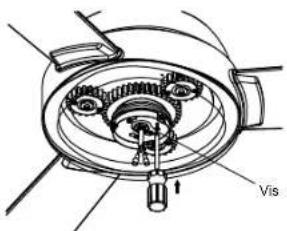
text_image
Technical diagram of a mechanical assembly with labeled components and directional arrowFig. 25
INSTALLATION DU BOÎTIER DE COMMUTATEUR (SUITE)
natural_image
Black and white photo of a modern office ceiling fan with three blades (no text or symbols visible)natural_image
Line drawings of five different tools: screwdriver, wrench, ladder, pliers, and flatener (no text or symbols)natural_image
Technical line drawing of a mechanical component with labeled parts G and H (no text or symbols beyond labels)
J K
L

M