Lofty Palace - Garden furniture Blumfeldt - Free user manual and instructions
Find the device manual for free Lofty Palace Blumfeldt in PDF.

User questions about Lofty Palace Blumfeldt
0 question about this device. Answer the ones you know or ask your own.
Ask a new question about this device
Download the instructions for your Garden furniture in PDF format for free! Find your manual Lofty Palace - Blumfeldt and take your electronic device back in hand. On this page are published all the documents necessary for the use of your device. Lofty Palace by Blumfeldt.
USER MANUAL Lofty Palace Blumfeldt
natural_image
Abstract green circular logo with three curved segments (no text or symbols)
natural_image
Abstract green circular logo with two leaf-like shapes (no text or symbols)
natural_image
Abstract green circular logo with three leaf-like shapes forming a Y-shape (no text or symbols)Congratulations on purchasing this device. Please read the following instructions carefully and follow them to prevent possible damages. We assume no liability for damage caused by disregard of the instructions and improper use. Scan the QR code to get access to the latest user manual and more product information.
Estimado cliente,
text_image
QR code image containing encoded data, no visible human-readable text
text_image
QR code image containing encoded data, no visible human-readable text
text_image
QR code image containing encoded data, no visible human-readable text
text_image
QR code image containing encoded data, no visible human-readable text
text_image
QR code image containing encoded data, no visible human-readable textEINZELTEILE
natural_image
Technical line drawing of a mechanical structure with two circular insets showing pipe connections (no text or symbols)text_image
Diagram of a 3D structural framework with labeled nodes and edges, showing connections between nodes 4 and 5.text_image
Diagram illustrating a mechanical or electrical process with a curved spring and ring, showing transformation from a circular component to a vertical rod.natural_image
Isometric line drawing of a simple room layout with a central table and three adjacent rectangular units (no text or symbols)| 1 | Inclination bar ∅3.8 cm,powder-coated |  | x8 |
| 2 | Horizontal brace∅3.8 cm, powder coated |  | x9 |
| 3 | Horizontal brace∅3.8 cm, powder coated |  | x9 |
| 4 | Vertical brace ∅ 4.8 cm,powder coated |  | x8 |
| 5 | Vertical brace ∅ 4.8 cm,powder coated |  | x8 |
| 6 | Support tube for canopy,lower part |  | x3 |
| 7 | Support tube for canopy,upper part |  | x3 |
| 8/A | Corner piece forhorizontal braces |  | x2 |
| 9/A | Corner piece for verticalbraces |  | x4 |
| 10/B 4-way corner piece |  | x6 | |
| 11/C Foot plate | 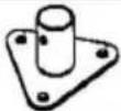 | x8 | |
| 12 Screw for foot plate | 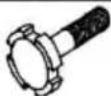 | x8 | |
| 13 | Fastening rubber withball end | 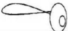 | x46 |
| 14 Tension cord for canopy |  | x3 | |
| 15 Peg for tension cord | 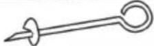 | x3 | |
| 16 Roof tarp x1 |  | ||
| 17 Long side tarpaulin without door |  | x1 | |
| 18 Long side tarpaulin with door |  | x1 | |
| 19 Front and rear tarpaulins |  | x2 | |
ASSEMBLY
text_image
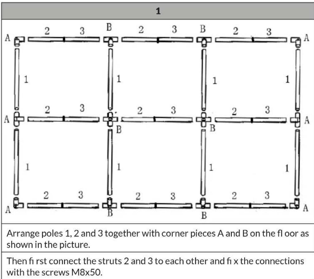
1 A 2 3 B 2 3 B 2 3 A 1 1 1 1 A 2 3 B 2 3 B 2 3 A 1 1 1 1 A 2 3 B 2 3 B 2 3 A Arrange poles 1, 2 and 3 together with corner pieces A and B on the floor as shown in the picture. Then first connect the struts 2 and 3 to each other and fi x the connections with the screws M8x50.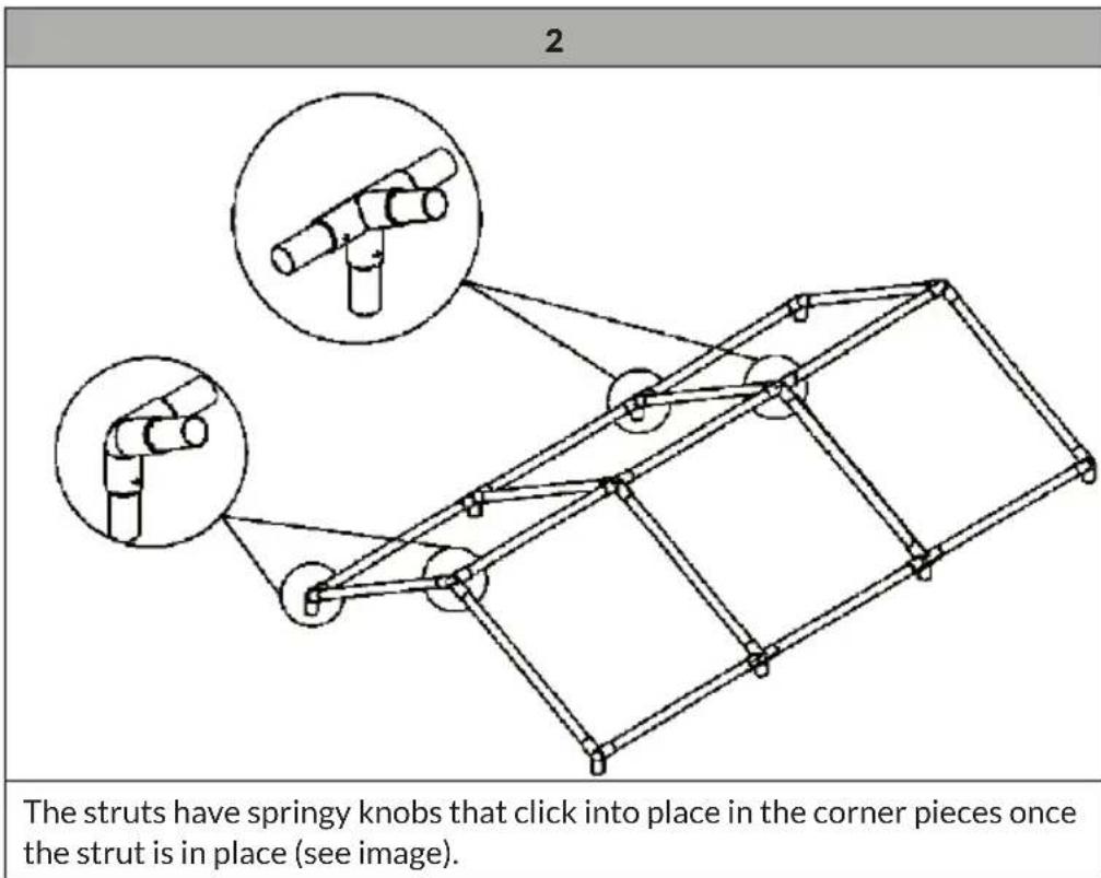
text_image
2 The struts have springy knobs that click into place in the corner pieces once the strut is in place (see image).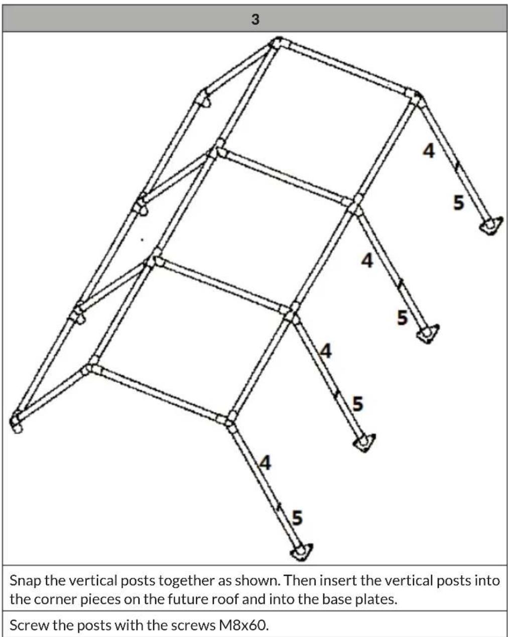
text_image
3 Snap the vertical posts together as shown. Then insert the vertical posts into the corner pieces on the future roof and into the base plates. Screw the posts with the screws M8x60.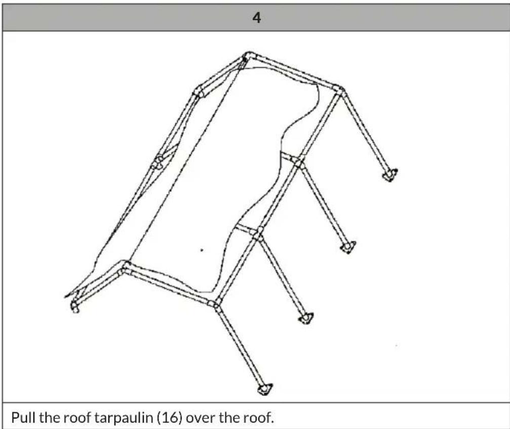
text_image
4 Pull the roof tarpaulin (16) over the roof.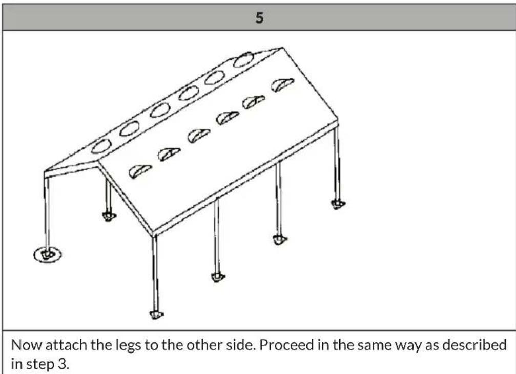
text_image
5 Now attach the legs to the other side. Proceed in the same way as described in step 3.6
text_image
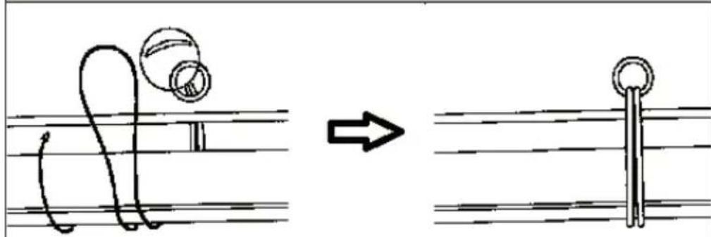
Diagram illustrating a musical instrument's motion from string to keyway, showing the waveform and keyway change.Fasten the tarpaulin to the frame by forming loops from the fastening rubbers (13).
7
natural_image
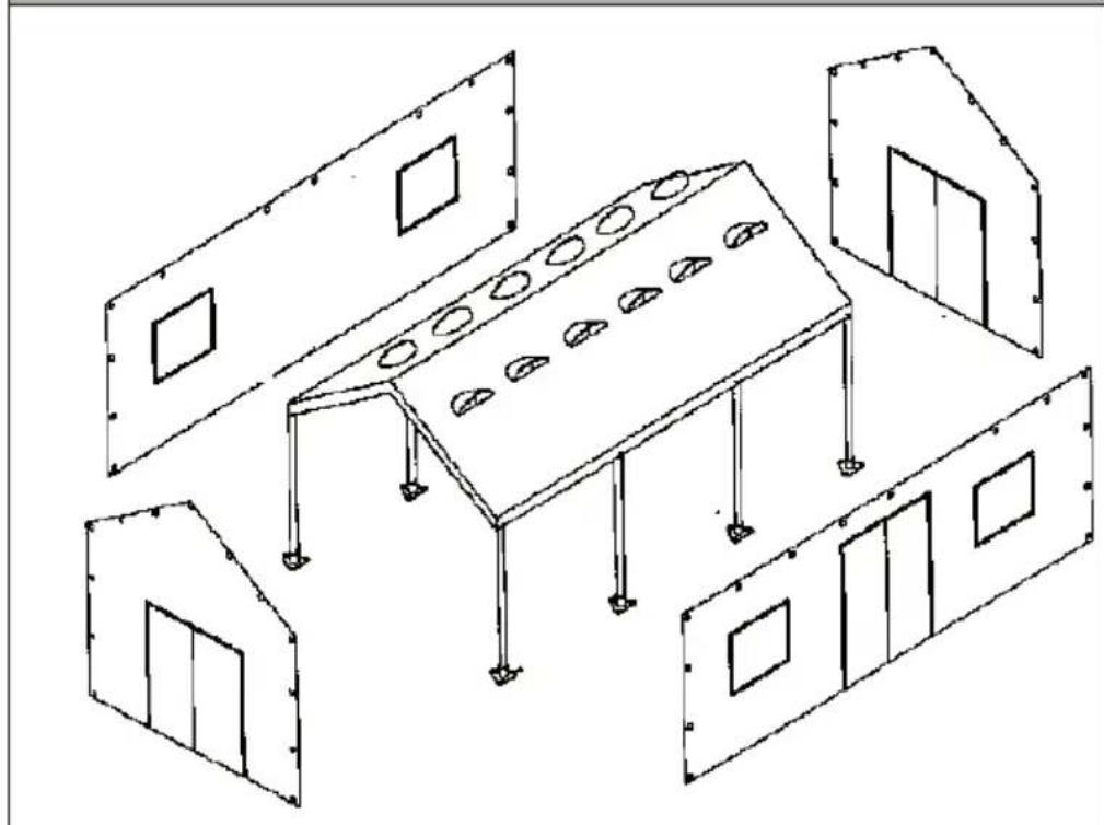
Isometric line drawing of a simple room layout with a central table and three adjacent rectangular units (no text or symbols)Attach the side parts to the frame with the fastening rubbers.
Raising the Side Roof
There are three eyelets on the underside of the long side tarpaulin without a door (17). Assemble the three support tubes (6 and 7) for the canopy and insert the upper pin through one of the eyelets. Now run the tension cord for the canopy over those eyelets and tie it to the ground with the pegs to use and stabilise the long wall as a roof.
PIEZAS
text_image
Diagram illustrating a mechanical or electrical process with a curved spring and ring, showing transformation from a circular component to a vertical rod.natural_image
Isometric line drawing of a simple room layout with a central table and three adjacent rectangular units (no text or symbols)natural_image
Technical line drawing of a mechanical structure with multiple connection nodes and two magnified insets showing pipe connections (no text or symbols)Berlin Brands Group UK Limited
PO Box 42
272 Kensington High Street
London, W8 6ND
United Kingdom