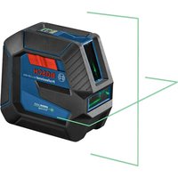
GLL 50-20 G Professional - Laser level BOSCH - Free user manual and instructions
Find the device manual for free GLL 50-20 G Professional BOSCH in PDF.

User questions about GLL 50-20 G Professional BOSCH
0 question about this device. Answer the ones you know or ask your own.
Ask a new question about this device
Download the instructions for your Laser level in PDF format for free! Find your manual GLL 50-20 G Professional - BOSCH and take your electronic device back in hand. On this page are published all the documents necessary for the use of your device. GLL 50-20 G Professional by BOSCH.
USER MANUAL GLL 50-20 G Professional BOSCH
IMPORTANT Read Before Using
IMPORTANT Lire avant usage
IMPORTANTE Leer antes de usar

natural_image
Icon of a person reading a book inside a circle (no text or symbols)Operating / Safety Instructions Consignes d'utilisation / de sécurité Instrucciones de funcionamiento y seguridad
GLL50-20 GLL50-20G
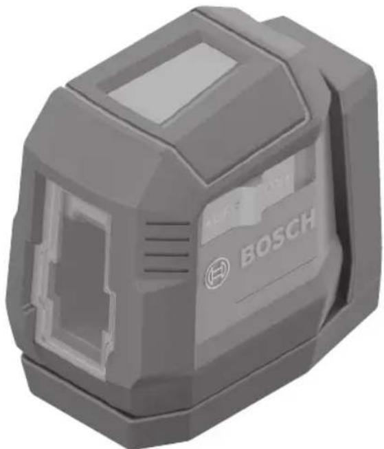
natural_image
3D rendering of a Bosch industrial sensor device (no text or symbols visible on body)
BOSCH
Call Toll Free for Consumer Information & Service Locations Pour obtenir des informations et les adresses de nos centres de service après-vente, appelez ce numéro gratuit Llame gratis para obtener información para el consumidor y ubicaciones de servicio
1-877-BOSCH99 (1-877-267-2499) www.boschtools.com
For English Version See page 2
natural_image
Diagram showing a device positioned at the intersection of two dashed lines, labeled 'A' in the top-left corner (no text or symbols on the device itself)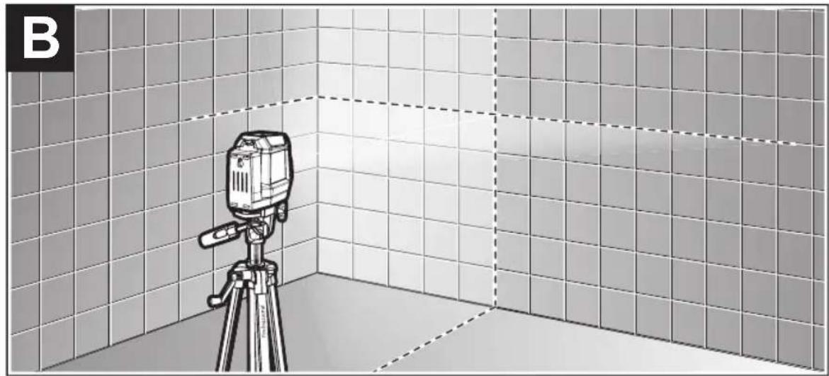
natural_image
Illustration of a camera on a tripod inside a tiled room with dashed lines indicating alignment or measurement (no text or symbols)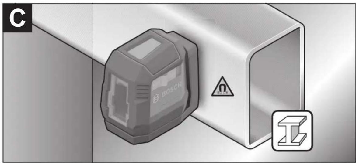
natural_image
Illustration of a Bosch 3D connector with warning symbol and I/O icon (no text or labels)D
text_image
BOSCH click!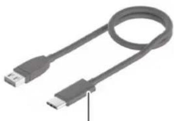
natural_image
Coiled USB cable with two connectors (no text or symbols visible)(15)
natural_image
Simple line drawing of a rectangular device with a label on the top (no text or symbols present)(16)

(17)
GLL20-50:
1 608 M00 05B
GLL20-50G:
1 608 M00 05J
(18)
natural_image
Line drawing of a tripod with adjustable legs and a head-mounted top (no text or symbols)BT 150 0 601 096 B10
Safety Symbols
| The definitions below describe the level of severity for each signal word.Please read the manual and pay attention to these symbols. | |
 | This is the safety alert symbol. It is used to alert you to potential personal injury hazards. Obey all safety messages that follow this symbol to avoid possible injury or death. |
 | DANGER indicates a hazardous situation which, if not avoided, will result in death or serious injury. |
 | WARNING indicates a hazardous situation which, if not avoided, could result in death or serious injury. |
 | CAUTION indicates a hazardous situation which, if not avoided, could result in minor or moderate injury. |
General Safety Rules
WARNING
Read all instructions. Failure to follow all instructions listed below may result in hazardous radiation exposure, electric shock, fire and/or serious injury.
The term "laser tool" in the warnings listed below refers to your battery-operated (cordless) laser tool.
SAVE ALL WARNINGS AND INSTRUCTIONS FOR FUTURE REFERENCE
The following label is on your tool for your safety. ALWAYS BE AWARE of its location when using the laser.
DO NOT direct the laser beam at persons or animals and do not stare into the laser beam yourself. This laser tool produces class 2 laser radiation and complies with 21
CFR 1040.10 and 1040.11 except for conformance with IEC 60825-1 Ed. 3., as described in Laser Notice No. 56, dated May 8, 2019." This can lead to persons being blinded.
DO NOT stare directly at the laser beam or project the laser beam directly into the eyes of others. Serious eye injury could result.
DO NOT place the laser tool in a position that may cause anyone to stare into the laser beam intentionally or unintentionally. Serious eye injury could result.
ALWAYS make sure that any bystanders in the vicinity of use are made aware of the dangers of looking directly into the laser tool.
Never aim the beam at a workpiece with a reflective surface. Bright shiny reflective sheet steel or similar reflective surfaces are not recommended for laser use. Reflective surfaces could direct the beam back towards the operator.
SAVE THESE INSTRUCTIONS 5
General Safety Rules
Use of controls or adjustments or performance of procedures other than those specified herein may result in hazardous radiation exposure.
DO NOT use any optical tools such as, but not limited to, telescopes or transits to view the laser beam. Serious eye injury could result.
DO NOT leave the laser tool "ON" unattended in any operation mode. ALWAYS turn the laser tool "OFF" when not in use. Leaving the laser tool "ON" increases the risk of someone inadvertently staring into the laser beam.
Do not use the laser viewing glasses as safety goggles. The laser viewing glasses are used for improved visualization of the laser beam, but they do not protect against laser radiation.
Do not use the laser viewing glasses as sun glasses or in traffic. The laser viewing glasses do not afford complete UV protection and reduce color perception.
ALWAYS position the laser tool securely. Damage to the laser tool and/or serious injury to the user could result if the laser tool falls.
DO NOT remove or deface any warning or caution labels. Removing labels increases the risk of exposure to laser radiation.
Battery tool use and care
Recharge only with the charger specified by the manufacturer. A charger that is suitable for one type of battery pack may create a risk of fire when used with another battery pack.
Use tool only with specifically designated battery packs. Use of any other battery packs may create a risk of injury and fire.
When battery pack is not in use, keep it away from other metal objects like paper clips, coins, keys, nails, screws, or other small metal objects that can make a connection from one terminal to another. Shorting the battery terminals together may cause burns or a fire.
Under abusive conditions, liquid may be ejected from the battery; avoid contact. If contact accidentally occurs, flush with water. If liquid contacts eyes, additionally seek medical help. Liquid ejected from the battery may cause irritation or burns.
Do not use a battery pack or tool that is damaged or modified. Damaged or modified batteries may exhibit unpredictable behaviour resulting in fire, EXPLOSION or risk of injury.
Do not expose a battery pack or tool to fire or excessive temperature. Exposure to fire or temperature above 265 °F (130 °C) may cause explosion.
Follow all charging instructions and do not charge the battery pack or tool outside the temperature range specified in the instructions. Charging improperly or at temperatures outside the specified range may damage the BATTERY and increase the risk of fire.
Disconnect the battery pack from the tool before making any adjustments, changing accessories, or storing the tool. Such preventive safety measures reduce the risk of starting the tool accidentally.
Do not modify or attempt to repair the tool or the battery pack except as indicated in the instructions for use and care.
Work area safety
Keep work area clean and well lit. Cluttered or dark areas invite accidents.
DO NOT operate the laser tool around children or allow children to operate the laser tool. Serious eye injury could result.
DO NOT use laser tools, attachments and accessories outdoors when lightning conditions are present.
Do not operate the measuring tool in explosive environments, such as in the presence of flammable liquids, gases or dusts. Sparks can be created in the measuring tool which may ignite the dust or fumes.
Electrical safety
WARNING Batteries can explode or leak, cause injury or fire. To
reduce this risk, always follow all instructions and warnings on the battery label and package.
DO NOT short any battery terminals.
DO NOT charge alkaline batteries.
6 SAVE THESE INSTRUCTIONS
General Safety Rules
DO NOT mix old and new batteries. Replace all of them at the same time with new batteries of the same brand and type.
DO NOT mix battery chemistries.
Dispose of or recycle batteries per local code.
DO NOT dispose of batteries in fire.
Keep batteries out of reach of children.
Remove batteries if the device will not be used for several months.
WARNING
Risk of fire and burns. Do not open, crush or heat C) or incinerate.
Personal safety
If laser radiation strikes your eye, you must deliberately close your eyes and immediately turn your head away from the beam.
Do not make any modifications to the laser equipment.
Stay alert, watch what you are doing and use common sense when operating a tool. Do not use a tool while you are tired or under the influence of drugs, alcohol or medication. A moment of inattention while operating a tool may result in serious personal injury or incorrect measurement results.
Use safety equipment. Always wear eye protection. Safety equipment such as dust mask, non-skid safety shoes, hard hat, or hearing protection used for appropriate conditions will reduce personal injuries.
Use caution when using laser tools in the vicinity of electrical hazards.
Magnets
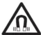
Keep the magnetic accessories away from implants or other medical devices such as pacemaker or insulin pumps. The magnets generate a field that can impair the function of implants or medical devices, which may lead to serious personal injury.
Keep the tool, positioning device, and laser target plate away from magnetic data medium and magnetically-sensitive equipment. The effect of the magnets of the tool and laser target plate can lead to irreversible data loss.
Use and care
Use the correct tool for your application. The correct tool will do the job better and safer.
Do not use the tool if the switch does not turn it on and off. Any tool that cannot be controlled with the switch is dangerous and must be repaired.
Store idle tool out of the reach of children and do not allow persons unfamiliar with the tool or these instructions to operate the tool. Tools are dangerous in the hands of untrained users.
Maintain tools. Check for misalignment or binding of moving parts, breakage of parts and any other condition that may affect the operation. If damaged, tool repaired before use. Many accidents are caused by poorly maintained tools.
Use the tool, accessories, etc., in accordance with these instructions and in the manner intended for the particular type of tool, taking into account the working conditions and the work to be performed. Use of the tool for operations different from those intended could result in a hazardous situation.
Service
Have your tool serviced by a qualified repair person using only identical replacement parts. This will ensure that the safety of the tool is maintained.
Develop a periodic maintenance schedule for tool. When cleaning a tool be careful not to disassemble any portion of the tool since internal wires may be misplaced or pinched or may be improperly mounted. Certain cleaning agents such as gasoline, carbon tetrachloride, ammonia, etc. may damage plastic parts.
SAVE THESE INSTRUCTIONS 7
FCC Caution
The manufacturer is not responsible for radio interference caused by unauthorized modifications to this equipment. Such modifications could void the user's authority to operate the equipment.
This device complies with Part 15 of the FCC Rules. Operation is subject to the following two conditions:
1) This device may not cause harmful interference, and
2) This device must accept any interference received, including interference that may cause undesired operation.
NOTE! This equipment has been tested and found to comply with the limits for a Class B digital devices, pursuant to Part 15 of the FCC rules. These limits are designed to provide reasonable protection against harmful interference in a residential installation. This equipment generates uses and can radiate radio frequency energy and, if not installed and used in accordance with the instructions, may cause harmful interference to radio communications. However, there is no guarantee that interference will not occur in a particular installation. If this equipment does cause harmful interference to radio or television reception, which can be determined by turning the equipment off and on, the user is encouraged to try to correct the interference by one or more of the following measures:
• Reorient or relocate the receiving antenna.
- Increase the separation between the equipment and receiver.
- Connect the equipment into an outlet on a circuit different from that to which the receiver is connected.
- Consult the dealer or an experienced radio/TV technician for help.
"Exposure to Radio Frequency (RF) Signals: The wireless device is a radio transmitter and receiver. It is designed and manufactured not to exceed the emission limit for exposure to radio frequency (RF) energy set by the Ministry of Health (Canada), Safety Code 6. These limits are part of comprehensive guidelines and established permitted levels of RF energy for the general population.
These guidelines are based on the safety standards previously set by international standard bodies. These standards include a substantial safety margin designed to assure the safety of all persons, regardless of age and health.
ISED Canada
This device contains licence-exempt transmitter(s)/receiver(s) that comply with Innovation, Science and Economic Development Canada's licence-exempt RSS(s). Operation is subject to the following two conditions:
(1) this device may not cause interference, and
(2) this device must accept any interference, including interference that may cause undesired operation of the device.
8 SAVE THESE INSTRUCTIONS
Specifications
| Model number GLL50-20 GLL50-20G | ||
| Article number 3601K65910 3601K65A10 | ||
| Working range ^1) | 50 ft (15 m) 65 ft (20m) | |
| Levelling Accuracy ^2) | ± 5/16 in. @ 30 ft.(± 8mm @ 10m) | ± 1/4 in. @ 30 ft.(± 7mm @ 10m) |
| Self-levelling range, typically ±3.5° | ||
| Operating temperature 14° F to 104° F (-10°C to +40°C) | ||
| Storage temperature -4° F to 158° F (-20°C to +70°C) | ||
| Max. altitude 6560 ft (2000 m) | ||
| Relative air humidity, max. 90% | ||
| Pollution degree according IEC 61010 2 | ^3) | |
| Laser class 2 | ||
| Laser type | < 5 mW, 630-650 nm | < 5 mW, 500 - 540 nm |
| Mount threading | 1/4"-20 | |
| C6 | 5 | |
| Divergence | 25 x 5 mrad (full angle) | |
| Protection rating | IP55 | |
| Weight | .77 lb (0.35 kg) | |
| Dimensions 4.1 x 2.5 x 3.9 in (104 x 64 x 100 mm) | ||
| Li-ion Battery pack (optional) | ||
| Type | BA 3.7V 1.0Ah A | |
| Article number 1 607 A35 ON9 | ||
| USB port | Type C | |
| Rated voltage | 3.7 V | |
| Capacity | 1.0 Ah | |
| Number of battery cells | 1 | |
| Power adaptor (recommended) | ||
| Output voltage 5.0 V | ||
| Output current 500 mA | ||
| Recommended power adaptor | 1 600 A01 43H | |
| Recommended USB Type-C® cable | 1 600 A01 6A8 | |
The tool can be clearly identified with the serial number on the type plate.
1) The working range can be decreased by unfavorable environmental conditions (e.g. direct sun exposure).
2) Valid when leveled (0°).
3) Conductive pollution occurs, or dry, non-conductive pollution occurs which becomes conductive due to condensation which is expected. In such conditions, equipment is normally protected against exposure to direct sunlight, precipitation, and full wind pressure, but neither temperature nor humidity is controlled.
SAVE THESE INSTRUCTIONS 9
Intended Use
The tool is intended for determining and checking horizontal and vertical lines. The laser tool is suitable exclusively for indoor operation in enclosed working sites.
SAVE THESE INSTRUCTIONS
Features
The numbering of the product features shown refers to the illustration of the tool on the graphic page.
1 Tripod mount 1/4"-20
2 Laser beam outlet
3 On/Off switch
4 Magnetic rotating mount
5 Fastening slot
6 Magnet
7 Charge indicator of the lithium-ion battery pack*
8 USB Type-C® port*
9 Lithium-ion battery pack*
10 Lithium-ion battery pack locking mechanism*
11 Latch of battery lid
12 Battery lid
13 Serial number
14 Laser warning label
15 USB Type-C ^® cable ^*
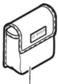
16 Protective bag*
17 Laser viewing glasses*
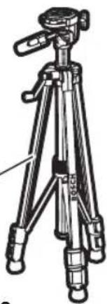
18 Tripod*
*not included.
Preparation
Power Supply
The tool can either be operated with commercially available LR6 (AA) batteries or with the Bosch rechargeable Lithium-ion battery pack (optional) outlined in the technical section of this manual.
Operation with LR6 (AA) batteries
Alkaline batteries (2 x 1.5 V LR6 (AA)) are recommended for the laser tool.
Press the locking mechanism 11 to open the battery compartment cover 12 and remove the battery compartment cover. Insert the batteries. When inserting, pay attention to the correct polarity according to the representation on the inside of the battery compartment.
Always replace all batteries at the same time. Only use batteries from one brand and with identical capacity.
Remove the batteries from the laser tool when not using it for extended periods. When storing for extended periods, the batteries can corrode and discharge themselves.
Operation with Bosch rechargeable lithium-ion battery packs (optional)
WARNING Follow all warnings and all instructions in the Bosch rechargeable lithium-ion battery pack manual before using the battery pack. Improper usage and recharge of battery pack may increase the risk of fire, personal injury and property damage.
WARNING Use only Bosch rechargeable lithium-ion battery packs listed in the technical data section of this manual. Use of other battery packs may increase the risk of fire, personal injury and property damage.
WARNING Remove the batteries from the tool when not using it for extended periods. When storing for extended periods, the batteries can corrode and self-discharge.
Note: The battery pack is supplied partially charged. To ensure full capacity of the battery pack, completely charge the battery pack with the USB power adapter (recommended) listed in the technical data section of this manual before using for the first time. See Bosch rechargeable lithium-ion battery pack manual for details.
WARNING Use only Bosch USB-C cable listed in the technical data section of this manual. Use of other USB-C cables may increase the risk of fire, personal injury and property damage.
The lithium-ion battery pack can be charged at any time without reducing its service life. Interrupting the charging procedure does not damage the battery pack.
The lithium-ion battery is protected against deep discharge by the Electronic Cell Protection (ECP). A protective circuit switches the laser level off when the battery is drained.
- Following the automatic shut off of the tool, do not continue to press the On/Off button. The battery can be damaged.
To insert the charged battery pack 9, slide it into the battery port until you feel it lock into position. Do not use force.
To remove the battery pack 9, press the locking mechanism 10 and pull the battery pack out of the battery port. Do not use force.
Operation
Initial Operation
WARNING
Do not leave the switched-on laser measure unattend-
ed and switch the laser measure off after use.
Other persons could be blinded by the laser beam.
WARNING
Do not point the laser beam at persons or animals and
do not look into the laser beam yourself, not even from a long distance.
Protect the laser measure against moisture and direct sun light.
Do not subject the tool to extreme temperatures or variations in temperature. As an example, do not leave it in vehicles for longer periods. In case of large variations in temperature, allow the tool to adjust to the ambient temperature before operation. In case of extreme temperatures or variations in temperature the accuracy of the tool can be impaired.
Avoid heavy impact or falling of the tool. After heavy exterior impact on the tool, an accuracy check should always be carried out before continuing to work.
Switch the tool off during transport. Slide the On/Off switch 3 to the "Off" position when transporting the measuring tool. This locks the leveling unit, which can be damaged in case of intense movement.
Switching On and Off
To switch on the tool, slide the On/Off switch 3 to the "On" position. Immediately after switching on, the tool sends laser beams from the laser beam outlets 2.
To switch off the tool, slide the On/Off switch 3 to the "Off" position. When switching off, the leveling unit is locked.
Application
The measuring tool is used for determining and checking horizontal and vertical lines.
Automatic Leveling
Working with Automatic Leveling
Position the tool on a level and firm base or to a tripod 18.
After switching on, the leveling function automatically compensates irregularities within the self-leveling range of ±3.5^ . The leveling is finished as soon as the laser beams no longer move.
If the measuring tool surface deviates more than ±3.5^ from the horizontal plane, then the automatic leveling function is not possible and the laser beams will flash. The lines will flash 1 s off 3 s on continually.
In this case, bring the tool to the level position and wait for the self-leveling to take place. As soon as the tool is within the self-leveling range of ±3.5^ , then the laser lines will continuously light up.
In case of ground vibrations or position changes during operation, the tool is automatically level again. To avoid errors, check the position of the horizontal and vertical laser line with regard to the reference points upon re-leveling.
Operation
Accuracy Check of the Measuring Tool
Influences on Accuracy
The largest influence is exerted by the ambient temperature. In particular, temperature differences that occur from the ground upwards can refract the laser beam.
In order to minimize thermal influences resulting from heat rising from the floor, it is recommended that you use the measuring tool on a tripod. In addition, position the measuring tool in the center of the work surface, wherever this is possible.
In addition to external influences, device-specific influences (e.g. falls or heavy impacts) can also lead to deviations. For this reason, check the levelling accuracy each time before beginning work.
First check the height accuracy and levelling accuracy of the horizontal laser line, then the levelling accuracy of the vertical laser line.
Should the measuring tool exceed the maximum deviation during one of the tests, please have it repaired by a Bosch after-sales service.
Checking the Height Accuracy of the Horizontal Line
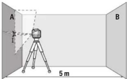
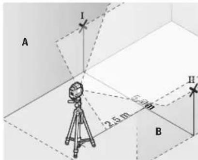
For this check, you will need a free measuring distance of 16ft (5 m) on firm ground between two walls (designated A and B).
- Mount the measuring tool close to wall A on a tripod, or place it on a firm, flat surface. Turn the measuring tool on the magnetic rotating mount 4 so that the laser outlet aperture 2 is not obstructed. Switch on the measuring tool.
— Aim the laser at the closer wall A and allow the measuring tool to level in. Mark the middle of the point at which the laser lines cross on the wall (point I).
text_image
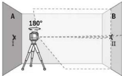
A B 5 m- Turn the measuring tool 180^ , allow it to level in and mark the point where the laser lines cross on the opposite wall B (point II).
text_image
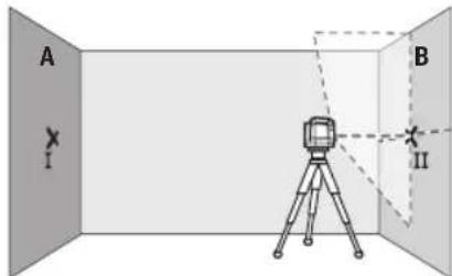
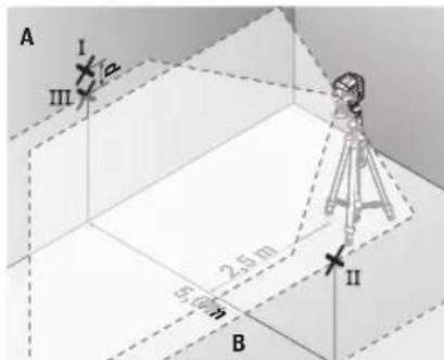
A 180° I B II- Position the measuring tool - without rotating it - close to wall B, switch it on and allow it to level in.
- Align the height of the measuring tool (using the tripod or by placing objects underneath as required) so that the point where the laser lines cross exactly hits the previously marked point II on wall B.
text_image
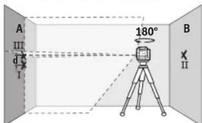
A I B II- Turn the measuring tool 180^ without adjusting the height. Aim it at wall A such that the vertical laser line runs through the already marked point I. Allow the measuring tool to level in and mark the point where the laser lines cross on wall A (point III).
text_image
A III d I 180° B II- The discrepancy d between the two marked points I and III on wall A reveals the actual height deviation of the measuring tool.
Operation
The maximum permitted deviation over the measuring distance of 2 × 16 ft = 32 ft ( 2 × 5 m = 10 m) is as follows:
GLL50-20: 32 ft x ±0.0098 in/ft = ±5/16 in (0.312 in) (10 m × ±0.8 mm/m = ±8 mm). The discrepancy d between points I and III must therefore amount to no more than 8 mm.
GLL50-20G: 32 ft x ±0.0078 in/ft = ±1/4 in (0.25 in) (10 m × ±0.7 mm/m = ±7 mm). The discrepancy d between points I and III must therefore amount to no more than 7 mm.
Checking the Level Accuracy of the Horizontal Line
For this check, you will need a free area of 16 × 16 ft ( 5 × 5 m).
- Mount the measuring tool in the middle between walls A and B on a tripod, or place it on a firm, level surface. Turn the measuring tool on the magnetic rotating mount 4 so that the laser outlet aperture 2 is not obstructed. Switch the measuring tool on and allow it to level in.
- At a distance of 8 ft (2.5 m) from the measuring tool, mark the center of the laser line on both walls (point I on wall A and point II on wall B).
text_image
A I 2.5 m 5.0 m II B- Set up the measuring tool at a 5 m distance and rotated by 180^ and allow it to level in.
text_image
A I II III 50 m 2.5 m B- Align the height of the measuring tool (using the tripod or by placing objects underneath as required) so that the center of the laser line exactly hits the previously marked point II on wall B.
— Mark the center of the laser line on wall A as point III (vertically above or below point I).
- The discrepancy d between the two marked points I and III on wall A reveals the actual horizontal deviation of the measuring tool.
The maximum permitted deviation over the measuring distance of 2 × 16 ft = 32 ft ( 2 × 5 m = 10 m) is as follows:
GLL50-20: 32 ft x ±0.0098 in/ft = ±5/16 in (0.312 in) (10 m × ±0.8 mm/m = ±8 mm). The discrepancy d between points I and III must therefore amount to no more than 8 mm.
GLL50-20G: 32 ft x ±0.0078 in/ft = ±1/4 in (0.25 in) (10 m × ±0.7 mm/m = ±7 mm). The discrepancy d between points I and III must therefore amount to no more than 7 mm.
Checking the Level Accuracy of the Vertical Line
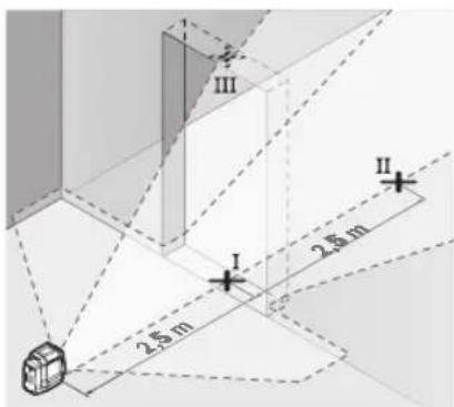
For this check, you will need a door opening (on solid ground) which has at least 8 ft (2.5 m) of space either side of the door.
— Place the measuring tool 8 ft (2.5 m) away from the door opening on a firm, flat surface (not on a tripod). Turn the measuring tool on the magnetic rotating mount 4 so that the laser outlet aperture 2 is not obstructed. Switch the measuring tool on and allow it to level in.
— Mark the center of the vertical laser line on the floor of the door opening (point I), 16 ft (5 m) away on the other side of the door opening (point II) and on the upper edge of the door opening (point III).
text_image
I II III 2.5 m 2.6 mOperation
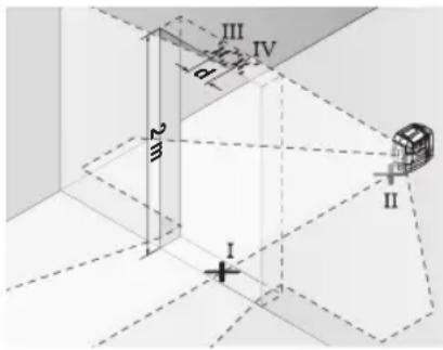
- Set up the measuring tool on the other side of the door opening, directly behind point II. Allow the measuring tool to level in and align the vertical laser line in such a way that its center passes through points I and II exactly.
text_image
III IV d m I II- Mark the center of the laser line on the upper edge of the door opening as point IV.
- The discrepancy d between the two marked points III and IV reveals the actual vertical deviation of the measuring tool.
— Measure the height of the door opening.
You can calculate the maximum permitted deviation as follows:
GLL50-20:
Doubled height of the door opening × 0.0098 in/ft (0.8 mm/m)
Example: At a door opening height of 6.5 ft (2 m), the maximum deviation amounts to 2 × 6.5 ft × ± 0.0098 in/ft = 0.13 in ( 2 × 2 m × ± 0.8 mm/m = ± 3.2 mm). The points III and IV must therefore be no further than 0.13 in (3.2 mm) from each other.
GLL50-20G:
Doubled height of the door opening × 0.0078 in/ft (0.7 mm/m)
Example: At a door opening height of 6.5 ft (2 m), the maximum deviation amounts to 2 × 6.5 ft × ± 0.0078 in/ft = 0.10 in ( 2 × 2 m × ± 0.7 mm/m = ± 2.8 mm). The points III and IV must therefore be no further than 2.8 mm from each other.
Working Advice
Always use the center of the laser line for marking. The width of the laser line changes with the distance.
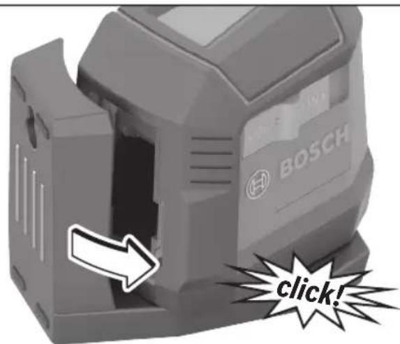
Attaching Using the Magnetic Rotating Mount (see figures C and D)
You can secure the measuring tool to magnetisable materials using the integrated magnetic rotating mount 4.
WARNING
Keep your fingers away from the rear side of the magnetic rotating mount while attaching the rotating mount to surfaces. The strong pulling force of the magnets 6 may jam your fingers.
Roughly align the magnetic rotating mount 4 before switching on the measuring tool.
Rotate the measuring tool on the magnetic rotating mount 4 to make the bottom laser point visible or to project heights with the horizontal laser point. If you switch off and transport the measuring tool, click it back into place on the rotating mount (see figure D).
Working with a Tripod (Accessory)
A tripod 18 offers a stable, height-adjustable measuring support. Place the tool via the tripod mount 1 onto the 1/4-20 male thread of the tripod and screw the locking screw of the tripod tight.
Laser Viewing Glasses (Accessory)
The laser viewing glasses 17 filter out the ambient light. This makes the light of the laser appear brighter to the eyes.
WARNING
Do not use the laser viewing glasses as safety goggles.
The laser viewing glasses are used for improved visualization of the laser beam, but they do not protect against laser radiation.
WARNING
Do not use the laser viewing glasses as sunglasses or in
traffic. The laser viewing glasses do not provide complete UV protection and reduce color perception.
Maintenance and Service
Keep the tool clean at all times.
Do not immerse the tool into water or other fluids.
Wipe off debris using a moist and soft cloth. Do not use any cleaning agents or solvents.
Regularly clean the surfaces of the laser beam outlets in particular, and pay attention to any fluff of fibers.
If the tool should fail despite the care taken in manufacturing and testing procedures, repair should be carried out by an authorized after-sales service center for Bosch power tools.
In all correspondence and spare parts orders, please always include the 10-digit article number given on the type plate of the tool.
ENVIRONMENT PROTECTION
Recycle raw materials & batteries instead of disposing of waste. The unit, accessories, packaging & used batteries should be sorted for environmentally friendly recycling in accordance with the latest regulations.
Limited warranty of bosch laser and measuring tool products
Robert Bosch Tool Corporation (“Seller”) warrants to the original purchaser only, that all Bosch lasers and measuring tools will be free from defects in material or workmanship for a period of one (1) year from date of purchase. Bosch will extend warranty coverage to two (2) years when you register your product within eight (8) weeks after date of purchase. Product registration card must be complete and mailed to Bosch (postmarked within eight weeks after date of purchase), or you may register on-line at www.boschtools.com/Service/ProductRegistration. If you choose not to register your product, a one (1) year limited warranty will apply to your product.
30 Day Money Back Refund or Replacement -
If you are not completely satisfied with the performance of your laser and measuring tools, for any reason, you can return it to your Bosch dealer within 30 days of the date of purchase for a full refund or replacement. To obtain this 30-Day Refund or Replacement, your return must be accompanied by the original receipt for purchase of the laser or optical instrument product. A maximum of 2 returns per customer will be permitted.
SELLER'S SOLE OBLIGATION AND YOUR EXCLUSIVE REMEDY under this Limited Warranty and, to the extent permitted by law, any warranty or condition implied by law, shall be the repair or replacement of parts, without charge, which are defective in material or workmanship and which have not been misused, carelessly handled, or misrepaired by persons other than Seller or Authorized Service Center. To make a claim under this Limited Warranty, you must return the complete Bosch laser or measuring tool, transportation prepaid, to any BOSCH Factory Service Center or Authorized Service Center. Please include a dated proof of purchase with your tool. For locations of nearby service centers, please use our on-line service locator or call 1-877-267-2499.
THIS WARRANTY PROGRAM DOES NOT APPLY TO TRIPODS AND RODS. Robert Bosch Tool Corporation (“Seller”) warrants tripods and leveling rods for a period of one (1) year from date of purchase.
THIS LIMITED WARRANTY DOES NOT APPLY TO OTHER ACCESSORY ITEMS AND RELATED ITEMS. THESE ITEMS RECEIVE A 90 DAY LIMITED WARRANTY.
To make a claim under this Limited Warranty, you must return the complete product, transportation prepaid. For details to make a claim under this Limited Warranty please visit www.boschtools.com or call 1-877-267-2499.
ANY IMPLIED WARRANTIES SHALL BE LIMITED IN DURATION TO ONE YEAR FROM DATE OF PURCHASE. SOME STATES IN THE U.S., AND SOME CANADIAN PROVINCES DO NOT ALLOW LIMITATIONS ON HOW LONG AN IMPLIED WARRANTY LASTS, SO THE ABOVE LIMITATION MAY NOT APPLY TO YOU.
IN NO EVENT SHALL SELLER BE LIABLE FOR ANY INCIDENTAL OR CONSEQUENTIAL DAMAGES (INCLUDING BUT NOT LIMITED TO LIABILITY FOR LOSS OF PROFITS) ARISING FROM THE SALE OR USE OF THIS PRODUCT. SOME STATES IN THE U.S., AND SOME CANADIAN PROVINCES DO NOT ALLOW THE EXCLUSION OR LIMITATION OF INCIDENTAL OR CONSEQUENTIAL DAMAGES, SO THE ABOVE LIMITATION MAY NOT APPLY TO YOU.
THIS LIMITED WARRANTY GIVES YOU SPECIFIC LEGAL RIGHTS, AND YOU MAY ALSO HAVE OTHER RIGHTS WHICH VARY FROM STATE TO STATE IN THE U.S., OR PROVINCE TO PROVINCE IN CANADA AND FROM COUNTRY TO COUNTRY.
THIS LIMITED WARRANTY APPLIES ONLY TO PRODUCTS SOLD WITHIN THE UNITED STATES OF AMERICA, CANADA AND THE COMMONWEALTH OF PUERTO RICO. FOR WARRANTY COVERAGE WITHIN OTHER COUNTRIES, CONTACT YOUR LOCAL BOSCH DEALER OR IMPORTER.
2 IEC 60825-1:2014 < 5 mW, 630-650 nm Laser Radiation. Do not stare into the
2 IEC 60825-1:2014 < 5 mW, 500-540 nm Laser Radiation. Do not stare into the
text_image
A I 2.5 mm 5.0 mm B Htext_image
I II III 2.5 m 2.5 mtext_image
III IV a b m I IILaser Radiation. Do not stare into the
Laser Radiation. Do not stare into the
text_image
A B I 5 mtext_image
A III d I 180° B X IItext_image
2.5 m I II IIIOperación
text_image
III IV d e II I© Robert Bosch Tool Corporation
1800 W. Central Road
Mt. Prospect, IL 60056-2230
160992AC2T 02/2025